ZA6AT140USBAT140
Alitronika DVS B.V.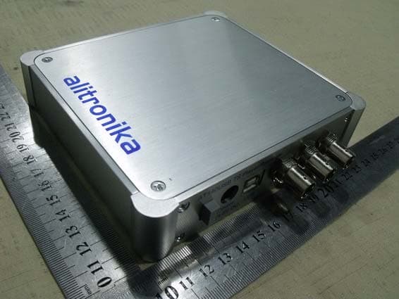
Click to zoom
Application Details
- Equipment Class
- JBP - Part 15 Class B Computing Device Peripheral
- Date of Grant
- Jun 01, 2011
- Application Purpose
- Original Equipment
- Date of Application
- Jun 01, 2011
- Equipment Note
- AT140
- Company
- Alitronika DVS B.V.
- Country
- Netherlands
Documents & Files
Document Text
Text extracted from the exhibit documents filed with the FCC. Open a document above to read the original.
Users Manual
Digital Video Interfacing Products DVSStation3 Integrated Transport Stream : - Player - Recorder - Analyser - Viewer - DVB to IP converter - File Editor Free, unlimited licence with every Alitronika device Standard FeaturesApplication - Universal Player and Recorder for feeding or recording to/from any digital video equipment. - Transport Stream Recording. - Transport Stream Playing. - Transport Stream Analysing - Transport Stream Monitoring. - Video on Demand Server. - Transport Stream Test Generator. - High Speed Data Link. - High performance MPEG-2 Stream Player, Recorder and Analyser supporting all Alitronika’s devices. - Automatically obtains the bitrate from the PCR during Recording and playing. - Accurate estimation of bitrate when there is none in the PCR. - Unlimited numbers of play loops & 3 record loops - Supports sub-loops, partial file play. - Recoding file selectable by size by duration of recording. - Automatic correction of PCR/PTS/DTS and continuity counter. - Integrated file information, (P)SI viewer. - Allows Null packet insertion using hardware only. - Allows PID filtering using hardware only. - Support for Hardware Null packet and counter packet generation for testing without any load on the PC. - Supports Error insertion. - Allows user to set TOT/TDT. - Supports Time Stamping using hardware only. - Integrated Hex editor for viewing/ Editing TS files. - Multiple application can be run simultaneously on the same PC for recoding or playing of multiple Streams. - Support unlimited number of LNB setting. - Support DVB-T/T2/S/S2/C/C2 Tuner settings. - Displays all operational registers of the hardware during play and record for diagnostics purposes. - Displays Hardware and software buffer usages during play and record operations. - Allows selection of DVB-ASI, DVB-SPI, RAW data, Burst or continuous mode. © 2009 Alitronika DVS DVSStation3www.alitronika.com 1 The layout of the DVSStation3 has the same familiar look as the DVSStation2 and many other application software’s. There are two basic screens, play & record. The screen shot below shows a typical record screen. As it can be seen the DVSStation3 has many functions, since it must support all Alitronika devices. Therefore not all of these functions & features are applicable to all devices. In general if a device does not support a function, then the option for selecting that function is disabled by the application software and is not selectable by the user. For example the play screen does not appear for devices that only have input and do not have any output capability, or the tuner settings only applies to the De-modulator devices such as AT800USB/PCI. In most cases the DVSStation3 pre-selects (Default) the options that are valid for a device. As an example when a device has only DVB-ASI output, then this output is automatically selected by the application and the user need not make any selections. 1.1 How to use DVSStation3 & all of it’s many Features & Functions The best way to learn to use DVSStation3 is actually to try it out. Since DVSStation3 is a FREE application software, it can be download it from our website & tried out. Without an Alitronika device, it automatically goes to Demo mode. In this mode a virtual device, called Demo device is used to demonstrate as many function of DVSStation3 as possible. Most features & functions work in this mode, including the Quick Real Time TS Analyzer. Another important point to make here is how to use the application software most efficiently with minimum of CPU usage. Most of the major functions of Alitronika devices are carried out by the hardware, such as modulation, de-modulation, coding & de-coding of DVB-ASI & SMPTE signals, conversion of DVB-ASI to DVB-SPI or DVB-T/C/S into DVB-ASI and DVB-SPI, PID filtering, the Re-Mux function and so on. Some features are carried out by the software. These include all of the features in the “Goodies” section, such as the TS Analyzer, Viewer, DVB-IP conversion. Other features like the “Constellation diagram” for some de-modulator devices are entirely software based. Users are advised to disable these functions when not needed in order to save CPU & memory usage. The hardware functions have no effect on the CPU/Memory usage. 1 GENERAL DESCRIPTION © 2009 Alitronika DVS DVSStation3www.alitronika.com 2 1.2 Selecting a Device DVSStation3 supports all Alitronika devices. Multiple devices could be used on one PCI/Laptop and multiple instances of DVSStation3 can run on the same PC/Laptop. The device selection works as follows: -No device present : DVSStation3 automatically enters Demo mode. -Only one device is present : DVSStation3 automatically selects it. -More than one devices are present : Dvsstation3 asks the user to select the device before the session starts. -If there are only 2 devices present and one is in use, when a 2 nd instance of DVSStation3 is opened it automatically selects the remaining device. If even more devices are present then DVSStation3 will ask the user to select a device and so on. Notice -The Demo device is always present & can be selected. -At anytime the user can re-select another device within DVSStation3 via Device Select tab. -the device (s) already in use are shown in the appropriate ( Devices already in use ) column. -Devices which support multiple standards are also treated as multiple devices. For example the AT2780USB is treated as 3 modulator devices DVB-T/H, DVB-C or ATSC-8VSB. This is because AT2780USB is REALLY 3 devices in one! The size & complexity of the modulation schemes makes it impossible to fit inside such a small device. We remind you that our modulators are 100% hardware based, hence require no or small CPU usage. © 2009 Alitronika DVS DVSStation3www.alitronika.com 3 1.3 Device Initialization After selecting a device, DVSStation3 shows the screen below. During the Initializing a device, DVSStation3 carries out the following operations: -Up-loads any firmware needed to make the device oper…
Text truncated - open the document above for the full version.
Block Diagram
AA BB CC DD EE 4 4 3 3 2 2 1 1 BNC FPGA - Processing Unit Clock Gereration 54MHz PowerSupplySection USB Controller Memory Block USB Connector ASI Input CircutryASI OutputCircutry BNCBNC CompactFlash InterfaceCompactFlash AT40USB - Balock Diagram 0 (C) ALI AIVANIALITRONIKA DIGITAL VIDEO SYSTEMSKALMARWEG 16/3GRONINGEN, NETHERLANDS 11 Monday, April 18, 2011 Size Document Number Rev Date: Sheet of
Cover Letter(s)
SCS-F18: Project and Product Certification Representative Authorization Letter Page 1 of 2 Rev 2.0 2206 Ringwood Avenue San Jose, CA 95131 Tel: 408-526-1188 Fax: 408-526-1088 Email: [email protected] Project and Product Certification Representative Authorization Letter Revision History Reason for Amendment (current / obsolete) From To Approved Date Initial Release (current) 1.0 1.0 Nov-14-2006 Revised wording (current) 1.0 2.0 Sept–25-2007 SCS-F18: Project and Product Certification Representative Authorization Letter Page 2 of 2 Rev 2.0 Alitronika DVS B.V. 2011-02-24 To: SIEMIC, INC. 2206 Ringwood Avenue, San Jose, CA 95131 USA Dear Sir/Madam, Re: Project and Product Certification Representative Authorization Letter We, Alitronika DVS B.V. hereby authorize SIEMIC, INC. to act as a Certification Body for certifying for the following project(s): (AT140, AT140USB) We affirm that between SIEMIC and Alitronika DVS B.V. any difference in understanding, including test plan, measurement methods, applicable standards and relevant procedures and processes have been resolved prior to commencement of testing activities. Sincerely, Signature Ali Aivani / Managing Director E-mail: : [email protected] Phone: +31-50-7851171 Fax: +31-85-7105855 Address : Kalmarweg 16/3, 9723 JG Groningen, The Netherlands
Cover Letter(s)
SCS-F19: Confidentiality Request Letter Rev 1.0 Nov 14, 2006 Confidentiality Request Letter Revision History Reason for Amendment (current / obsolete) From To Approved Date Initial Release (current) 1.0 1.0 Nov-14-2006 SCS-F19: Confidentiality Request Letter Rev 1.0 Nov 14, 2006 Alitronika DVS B.V. (2010-11-24) To: Federal Communications Commission Authorization and Evaluation Division Confidentiality Request regarding application for certification of FCC ID: ZA6AT140USB We hereby request confidential treatment of information accompanying this application as outlined below: - Schematic The above materials contain trade secrets and proprietary information not customarily released to the public. The public disclosure of these materials may be harmful to the applicant and provide unjustified benefits to its competitors. The applicant understands that pursuant to Section 0.457 and 0.459 of the Rules, disclosure of this application and all accompanying documentation will not be made before the date of the Grant for this application. Sincerely, Signature Ali Aivani / Managing Director E-mail: : [email protected] Phone: +31-50-7851171 Fax: +31-85-7105855 Address : Kalmarweg 16/3, 9723 JG Groningen, The Netherlands
External Photos
External of EUT
ID Label/Location Info
FCC ID Label FCC ID: ZA6AT140USB Model Number: AT140USB Made in Netherlands This device complies with Part 15 of the FCC Rules. Operation is subject to the following two conditions: (1) this device may not cause harmful interference, and (2) this device must accept any interference received, including interference that may cause undesired operation
ID Label/Location Info
Label Location Proposed Label Location on EUT
Internal Photos
Internal of EUT
Operational Description
Product illustration 1. Function introduce The AT140USB a DVB-ASI Player/Recorder It is capable of recording a Transport Stream file into the Harddisk of the PC or its internal Compact Flash, from an external DVB-ASI source or playing back a transport stream from the PC or its internal Compact Flash, into any DVB-ASI compatible device. 2. Structure 2.1 Structure Introduce The system consists of a FPGA ( Filed Programmable Gate Array ) device, DVB-ASI input & output devices, a USB controller & DC/DC power supplies. 2.2 Description When connected to USB port of a PC, under control the application software, DVSStation3, this device can be used as a Transport Stream player or recorder. When not connected to a PC, the deice plays back or records onto the internal Compact Flash on board the device. 2.3 Power The device requires a 5V @ 2A external power supply.
Test Report
FCC ID: ZA6AT140USB SHENZHEN EMTEK CO., LTD. Report No.: ES110127175F Page 1 of 22 EMC TEST REPORT For Alitronika DVS B.V. AT140 Model No.: AT140USB FCC ID: ZA6AT140USB Report Number : ES110127175F Date of Test : January 28, 2011 to February 20, 2011 Date of Report : February 21, 2011 Prepared for : Alitronika DVS B.V. Address : Kalmarweg 16/3, 9723 JG Groningen,The Netherlands Prepared by : SHENZHEN EMTEK CO., LTD. Address : Bldg 69, Majialong Industry Zone, Nanshan District, Shenzhen, Guangdong, China Tel: (0755) 26954280 Fax: (0755) 26954282 FCC ID: ZA6AT140USB SHENZHEN EMTEK CO., LTD. Report No.: ES110127175F Page 2 of 22 TABLE OF CONTENT Test Report Description Page 1. SUMMARY OF TEST RESULT ..................................................................................................... 4 2. GENERAL INFORMATION........................................................................................................... 5 2.1. Description of Device (EUT) ....................................................................................................... 5 2.2. Description of Test Facility .......................................................................................................... 5 2.3. Description of Support Device..................................................................................................... 6 2.4. Measurement Uncertainty ............................................................................................................ 6 3. MEASURING DEVICE AND TEST EQUIPMENT ..................................................................... 7 3.1. For Power Line Conducted Emission Measurement.................................................................... 7 3.2. For Radiated Emission Measurement (3m) ................................................................................. 7 4. POWER LINE CONDUCTED EMISSION MEASUREMENT .................................................. 8 4.1. Block Diagram of Test Setup ....................................................................................................... 8 4.2. Measuring Standard ..................................................................................................................... 8 4.3. EUT Configuration on Measurement...........................................................................................8 4.4. Operating Condition of EUT........................................................................................................ 9 4.5. Test Procedure.............................................................................................................................. 9 4.6. Measuring Results........................................................................................................................ 9 5. RADIATED EMISSION MEASUREMENT.................................................................................11 5.1. Block Diagram of Test Setup ..................................................................................................... 11 5.2. Measuring Standard ................................................................................................................... 11 5.3. Radiated Emission Limits (Class B) .......................................................................................... 12 5.4. EUT Configuration on Test ........................................................................................................ 12 5.5. Operating Condition of EUT...................................................................................................... 12 5.6. Test Procedure............................................................................................................................ 12 5.7. Measuring Results...................................................................................................................... 13 6. PHOTOGRAPHS............................................................................................................................ 17 6.1. Photos of Power Line Conducted Emission Measurement ........................................................ 17 6.2. Photos of Radiation Emission Measurement ............................................................................. 17 APPENDIX I (Photos of EUT) (3 Pages) FCC ID: ZA6AT140USB SHENZHEN EMTEK CO., LTD. Report No.: ES110127175F Page 3 of 22 TEST REPORT DESCRIPTION Applicant : Alitronika DVS B.V. Manufacturer : MECALEC SMD Trade Mark : Alitronika EUT : AT140 Model No. : AT140USB FCC ID : ZA6AT140USB Power Supply : AC 100-240V, 50-60Hz, 0.35A Measurement Procedure Used: FCC Rules and Regulations Part 15 Subpart B Class B October 2009 & FCC / ANSI C63.4-2009 The device described above is tested by SHENZHEN EMTEK CO., LTD. to determine the maximum emission levels emanating from the device and the severe levels of the device can endure and its performance criterion. The measurement results are contained in this test report and SHENZHEN EMTEK CO., LTD. is assumed full of responsibility for the accuracy and completeness of these measurements. Also, this report shows that the EUT (Equipment Under Test) is technically compliant with the FCC requirements. This report applies to above tested sample only and shall not be reproduced in part without written approval of SHENZHEN EMTEK CO., LTD. Date of Test : January 28, 2011 to February 20, 2011 Prepared by : (Engineer) Reviewer : (Quality Manager) Approved & Authorized Signer : (Manager) FCC ID: ZA6AT140USB SHENZHEN EMTEK CO., LTD. Report No.: ES110127175F Page 4 of 22 1. SUMMARY OF TEST RESULT EMISSION Description of Test Item Standard & Limits Results Conducted Disturbance at Mains Terminals FCC Part 15, Subpart B, Class B ANSI C63.4: 2009 Pass Radiated Disturbance FCC Part 15, Subpart B, Class B ANSI C63.4: 2009 Pass Note: N/A is an abbreviation for Not Applicable. FCC ID: ZA6AT140USB SHENZHEN EMTEK CO., LTD. Report No.: ES110127175F Page 5 of 22 2. GENERAL INFO…
Text truncated - open the document above for the full version.
Test Setup Photos
RADIATED EMISSION TEST CONDUCTED EMISSION TEST
Contact Information
Applicant
Ali Aivani(Managing Director)
Test Firm
EMTEK (Shenzhen) Co., Ltd.David Lee
Technical Specifications
| # | Rule Parts | Frequency Range | Power Output |
|---|---|---|---|
| 1 | 15B | - | - |
Other Applications from Alitronika DVS B.V.
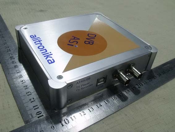
ZA6AT40USB
Jun 01, 2011AT40
Equipment Class
JBP - Part 15 Class B Computing Device Peripheral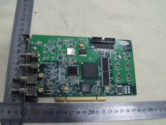
ZA6AT2900PCI
May 30, 2011AT2900P
Equipment Class
JBP - Part 15 Class B Computing Device Peripheral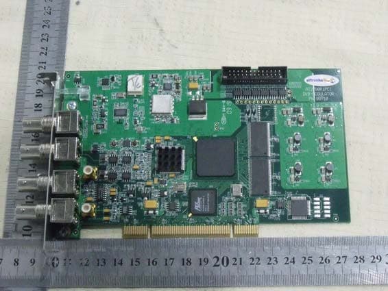
ZA6AT2780PCI
May 30, 2011AT2780
Equipment Class
JBP - Part 15 Class B Computing Device Peripheral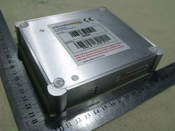
ZA6AT290USB
May 23, 2011iMod-S
Equipment Class
JBP - Part 15 Class B Computing Device Peripheral