ZA6AT2780PCIAT2780
Alitronika DVS B.V.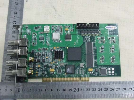
Click to zoom
Application Details
- Equipment Class
- JBP - Part 15 Class B Computing Device Peripheral
- Date of Grant
- May 30, 2011
- Application Purpose
- Original Equipment
- Date of Application
- May 30, 2011
- Equipment Note
- AT2780
- Company
- Alitronika DVS B.V.
- Country
- Netherlands
Documents & Files
Document Text
Text extracted from the exhibit documents filed with the FCC. Open a document above to read the original.
Users Manual
Alitronika DVS DVSStationX4 DVSStation4 - Standard Features: • High performance MPEG-2 stream player, recorder and analyser. • Can combined up to 4 input and de-combine 4 outputs • Automatically obtains bit rate from the PCR during recording and playing. • Accurate estimation of bit rate when there is none in the PCR. • Recoding file selectable by size by duration of re- cording. • Allows PID filtering using hardware only. • Support for hardware null packet and counter packet generation for testing without any load on the PC. • Multiple application can be run simultaneously on the same PC for recording or playing of multiple streams Applications: • Universal MPEG-2 transport stream generator and re- corder for feeding or re- cording. To or from any digital video equipments. • High speed serial data link. • Transport stream recording. • Transport stream playing. • Transport stream analysing. • Transport stream monitoring. Digital Video Interfacing Integrated Transport System Player Recorder Analyser Alitronika DVS DVSStationX4 1.0 The “play” application: 1.1 Selecting a TS file to play: To select a file to play simply click on “select file name” and choose the file you want from the files on your computer and click open. You can choose up to 4 files to run in one session. You can also open a .ATS file which contains data for all four outputs. Alitronika DVS DVSStationX4 1.2 Selecting the level of output bit rate: To select the level of bit rate in your output you simply select the edit box above your out- puts file information and choose the bit rate level you require. Alitronika DVS DVSStationX4 1.4 The play panel: The play panel is located at the top of the application screen. It consist of a play and a stop button, when you click play ALL of the selected files will play simultaneously and when you click stop ALL of the selected files will stop simultaneously. 1.5 The “File Information” panel: This panel displays the file properties. For example it displays are the name of the file, the playtime in seconds, the bit rate, the number of bytes and the packet size. 1.6 The “Program Information” panel: This panel shows most of the useful information about the content of the TS (Transport Stream). For example it shows each of the programs carried on the TS. Clicking on a particular program gives you information on it, such as the program number, the provider and information as to whether the data is purely visual, audio or both. Alitronika DVS DVSStationX4 1.7 Test Data Generation Clicking generate test data will suspend play back on the selected output and cause the card to output hardware generated test data. This can either be NULL packets or counter packets Alitronika DVS DVSStationX4 2.0 the “Record and Monitor” application: 2.1 Recording options: Users can choose the size of the file to be recorded by typing a number into the box and deciding whether to decide the size of the file in Seconds or MBytes. Meaning that if you type 100 into the box you can choose to record until you reach 100 Mbytes or 100 Sec- onds. Alitronika DVS DVSStationX4 2.2 PID filtering: All Alitronika devices with input support PID filtering because, some applications may re- quire PID filtering in order to reduce the amount of data, so that further processing can take place. There are two PID filtering options; you can choose to “Ignore selected PID’s” or to “Record selected PID’s”. Having both these options makes using this application eas- ier for example if you wanted to record all but one of the PID’s you would choose to “Ignore selected PID’s” and tick the box next to the PID you don't want to record, whereas if you only wanted to record one of the PID’s you would “Record selected PID’s” and tick the box corresponding to the PID you do want to record. In order to bring up the PID table that allows you to select which PID’s you do or don’t want to record, you simply need to press the “PID Table” button for the input you are working with. Alitronika DVS DVSStationX4 2.2 Carrier detection, lock and synchronization. Alitronika devices that have DVB-ASI inputs, first detect the presence of a valid signal, then the receiver modules on board these devices lock into the incoming TS if needed after decoding, and then synchronise to the input TS. There are three indicators showing the status of each of these (carrier detection, lock and synchronisation). A red colour indicates a lack of a valid signal of lock or the device isn’t able to synchronize to the input stream. When everything is correct, normal operating condition, the indicators all show green. The enable TS Analyser( Program Information) allow the analysis of the transport stream for program information to be turned on and off on a channel by channel basis. Warning statement This equipment has been tested and found to comply with the limits for a Class B digital device, pursuant to part 15 of the FCC Rules. These limits are designed to provide reasonable protection against harmful interference in a residential installation. This equipment generates, uses and can radiate radio frequency energy and, if not installed and used in accordance with the instructions, may cause harmful interference to radio communications. However, there is no guarantee that interference will not occur in a particular installation. If this equipment does cause harmful interference to radio or television reception, which can be determined by turning the equipment off and on, the user is encouraged to try to correct the interference by one or more of the following measures: • Reorient or relocate the receiving antenna. • Increase the separation between the equipment and receiver. • Connect the equipment into an outlet on a circuit different from that to which the receiver is connected. • Consult the dealer or an experienced radio/TV technician for help. Caution: Any changes or modifications to this device not explicitly approved by manufacturer could void your authority to operate this…
Text truncated - open the document above for the full version.
Block Diagram
AA BB CC DD EE 4 4 3 3 2 2 1 1 BNCBNCBNCBNC RF Section Circutry IF Section Circutry ASI Input CircutryASI Output Circutry FPGA - Processing Unit Clock Gereration 54MHz 66MHz PowerSupplySection PCI BUSPCI Controller Memory Block AT2780PCI - Balock Diagram 0 (C) ALI AIVANIALITRONIKA DIGITAL VIDEO SYSTEMSKALMARWEG 16/3GRONINGEN, NETHERLANDS 11 Monday, April 18, 2011 Size Document Number Rev Date: Sheet of
Cover Letter(s)
SCS-F18: Project and Product Certification Representative Authorization Letter Page 1 of 2 Rev 2.0 2206 Ringwood Avenue San Jose, CA 95131 Tel: 408-526-1188 Fax: 408-526-1088 Email: [email protected] Project and Product Certification Representative Authorization Letter Revision History Reason for Amendment (current / obsolete) From To Approved Date Initial Release (current) 1.0 1.0 Nov-14-2006 Revised wording (current) 1.0 2.0 Sept–25-2007 SCS-F18: Project and Product Certification Representative Authorization Letter Page 2 of 2 Rev 2.0 Alitronika DVS B.V. 2011-02-24 To: SIEMIC, INC. 2206 Ringwood Avenue, San Jose, CA 95131 USA Dear Sir/Madam, Re: Project and Product Certification Representative Authorization Letter We, Alitronika DVS B.V. hereby authorize SIEMIC, INC. to act as a Certification Body for certifying for the following project(s): (AT2780, AT2780PCI) We affirm that between SIEMIC and Alitronika DVS B.V. any difference in understanding, including test plan, measurement methods, applicable standards and relevant procedures and processes have been resolved prior to commencement of testing activities. Sincerely, Signature Ali Aivani / Managing Director E-mail: : [email protected] Phone: +31-50-7851171 Fax: +31-85-7105855 Address : Kalmarweg 16/3, 9723 JG Groningen, The Netherlands
External Photos
EUT
ID Label/Location Info
FCC ID Label FCC ID: ZA6AT780PCI Model Number: AT780PCI Made in Netherlands This device complies with Part 15 of the FCC Rules. Operation is subject to the following two conditions: (1) this device may not cause harmful interference, and (2) this device must accept any interference received, including interference that may cause undesired operation
ID Label/Location Info
Label Location Proposed Label Location on EUT
Internal Photos
EUT
Test Report
FCC ID:ZA6AT2780PCI SHENZHEN EMTEK CO., LTD. Report No.: ES110127173F Page 1 of 25 EMC TEST REPORT For Alitronika DVS B.V. AT2780 Model No.: AT2780PCI FCC ID: ZA6AT2780PCI Report Number : ES110127173F Date of Test : January 28, 2011 to February 20, 2011 Date of Report : February 21, 2011 Prepared for : Alitronika DVS B.V. Address : Kalmarweg 16/3, 9723 JG Groningen,The Netherlands Prepared by : SHENZHEN EMTEK CO., LTD. Address : Bldg 69, Majialong Industry Zone, Nanshan District, Shenzhen, Guangdong, China Tel: (0755) 26954280 Fax: (0755) 26954282 FCC ID:ZA6AT2780PCI SHENZHEN EMTEK CO., LTD. Report No.: ES110127173F Page 2 of 25 TABLE OF CONTENT Test Report Description Page 1. SUMMARY OF TEST RESULT ..................................................................................................... 4 2. GENERAL INFORMATION........................................................................................................... 5 2.1. Description of Device (EUT) ....................................................................................................... 5 2.2. Description of Support Device..................................................................................................... 5 2.3. Description of Test Facility .......................................................................................................... 5 2.4. Measurement Uncertainty ............................................................................................................ 6 3. MEASURING DEVICE AND TEST EQUIPMENT ..................................................................... 7 3.1. For Power Line Conducted Emission Measurement.................................................................... 7 3.2. For Radiated Emission Measurement (3m) ................................................................................. 7 4. POWER LINE CONDUCTED EMISSION MEASUREMENT .................................................. 8 4.1. Block Diagram of Test Setup ....................................................................................................... 8 4.2. Measuring Standard ..................................................................................................................... 8 4.3. EUT Configuration on Measurement...........................................................................................8 4.4. Operating Condition of EUT........................................................................................................ 9 4.5. Test Procedure.............................................................................................................................. 9 4.6. Measuring Results........................................................................................................................ 9 5. RADIATED EMISSION MEASUREMENT................................................................................ 10 5.1. Block Diagram of Test Setup ..................................................................................................... 10 5.2. Measuring Standard ................................................................................................................... 10 5.3. Radiated Emission Limits (Class B) .......................................................................................... 11 5.4. EUT Configuration on Test ........................................................................................................ 11 5.5. Operating Condition of EUT...................................................................................................... 11 5.6. Test Procedure............................................................................................................................ 11 5.7. Measuring Results...................................................................................................................... 12 6. PHOTOGRAPHS............................................................................................................................ 22 6.1. Photos of Power Line Conducted Emission Measurement ........................................................ 22 6.2. Photos of Radiation Emission Measurement ............................................................................. 22 APPENDIX I (Photos of EUT) (1 Page) FCC ID:ZA6AT2780PCI SHENZHEN EMTEK CO., LTD. Report No.: ES110127173F Page 3 of 25 TEST REPORT DESCRIPTION Applicant : Alitronika DVS B.V. Manufacturer : MECALEC SMD Trade Mark : Alitronika EUT : AT2780 Model No. : AT2780PCI FCC ID : ZA6AT2780PCI Power Supply : DC 5V & DC 3.3V from the PCI bus Measurement Procedure Used: FCC Rules and Regulations Part 15 Subpart B Class B October 2009 & FCC / ANSI C63.4-2009 The device described above is tested by SHENZHEN EMTEK CO., LTD. to determine the maximum emission levels emanating from the device and the severe levels of the device can endure and its performance criterion. The measurement results are contained in this test report and SHENZHEN EMTEK CO., LTD. is assumed full of responsibility for the accuracy and completeness of these measurements. Also, this report shows that the EUT (Equipment Under Test) is technically compliant with the FCC requirements. This report applies to above tested sample only and shall not be reproduced in part without written approval of SHENZHEN EMTEK CO., LTD. Date of Test : January 28, 2011 to February 20, 2011 Prepared by : (Engineer) Reviewer : (Quality Manager) Approved & Authorized Signer : (Manager) FCC ID:ZA6AT2780PCI SHENZHEN EMTEK CO., LTD. Report No.: ES110127173F Page 4 of 25 1. SUMMARY OF TEST RESULT EMISSION Description of Test Item Standard & Limits Results Conducted Disturbance at Mains Terminals FCC Part 15, Subpart B, Class B ANSI C63.4: 2009 Pass Radiated Disturbance FCC Part 15, Subpart B, Class B ANSI C63.4: 2009 Pass Note: N/A is an abbreviation for Not Applicable. FCC ID:ZA6AT2780PCI SHENZHEN EMTEK CO., LTD. Report No.: ES110127173F Page 5 of 25 2. GE…
Text truncated - open the document above for the full version.
Test Setup Photos
RADIATED EMISSION TEST CONDUCTED EMISSION TEST
Contact Information
Applicant
Ali Aivani(Managing Director)
Test Firm
EMTEK (Shenzhen) Co., Ltd.David Lee
Technical Specifications
| # | Rule Parts | Frequency Range | Power Output |
|---|---|---|---|
| 1 | 15B | - | - |
Other Applications from Alitronika DVS B.V.
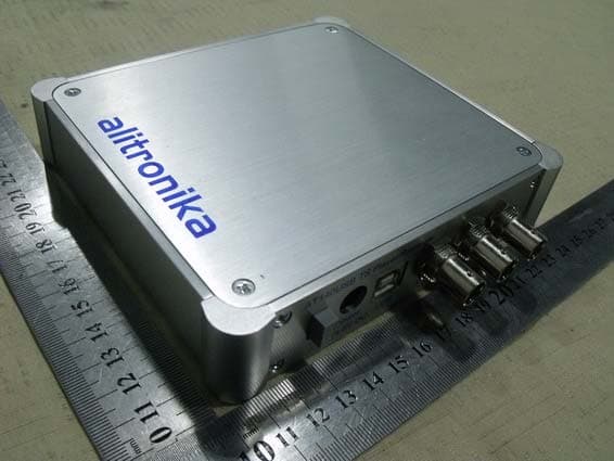
ZA6AT140USB
Jun 01, 2011AT140
Equipment Class
JBP - Part 15 Class B Computing Device Peripheral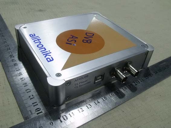
ZA6AT40USB
Jun 01, 2011AT40
Equipment Class
JBP - Part 15 Class B Computing Device Peripheral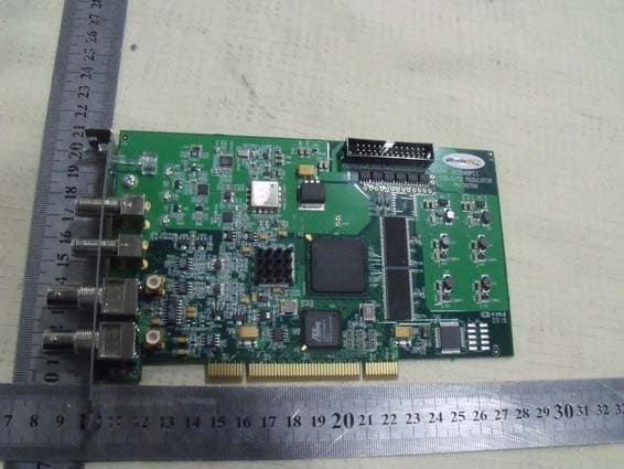
ZA6AT2900PCI
May 30, 2011AT2900P
Equipment Class
JBP - Part 15 Class B Computing Device Peripheral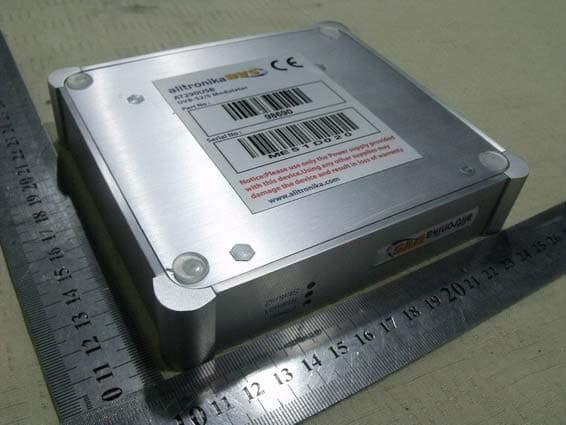
ZA6AT290USB
May 23, 2011iMod-S
Equipment Class
JBP - Part 15 Class B Computing Device Peripheral