ZAL261770RADAR DETECTOR
N7S Corp.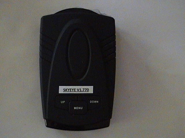
Click to zoom
Application Details
- Equipment Class
- CRD - Part 15 Radar Detector
- Date of Grant
- Jul 20, 2011
- Application Purpose
- Original Equipment
- Date of Application
- Jul 20, 2011
- Equipment Note
- RADAR DETECTOR
- Frequency Range
- 33400.00000000 - 36000.00000000
- Company
- N7S Corp.
- Country
- United States
Documents & Files
Document Text
Text extracted from the exhibit documents filed with the FCC. Open a document above to read the original.
Users Manual
SkyEye User Manual: Dear user, Congratulations and thank you for purchasing the RadarShields SkyEye™ all in one Radar, Laser and GPS based early warning speed enforcement defense system, this is the most advance system we have ever made! It will protect you from Radar, Laser, Red Light Cameras, Speed Cameras, traffic cameras, common speed trap locations and the very first unit to also include Aircraft speed enforced locations. Well, you wanted the best and we have created it for you! Mounting Your Unit: Mount the unit at the center of the windshield as low as possible for premium performance using the supplied suction cups mounting bracket. Power connection: The Skyeye is designed to operate with Dc12V positive vehicle electrical systems. Connect the power using the provided cable. First plug the small end of the power cable into the unit’s power jack. Second plug the large end of the power cable into the vehicle’s cigarette socket jack. If the unit does not operate even dough it is properly connected to the cigarette socket, check the socket and the fuse in the adaptor and vehicles fuse box carefully. Operation: The SkyeEye was designed to make it as easy as possible to operate, even dough it has so many features and options, it is basically ready for use as soon as you power it, simply plug and play! There are basically three buttons on the unit: the “UP” and “Down” buttons and the main “Menu” button. When first powering the unit it will go through its entire default programming sequence, each mode will be announced and its current setting. Menu: The Menu button is used to scroll through the different units settings and options, once you are in the desired mode simply use the UP/DOWN buttons to make any changes in the desired mode, one you are done simply stop depressing the UP/DOWN button, within 3 second the unit will beep confirming the selected setting was stored in the units memory. Note: All settings are stored in the unit’s memory and will conveniently remain after the unit is powered off, if you desire to make any changes to the unit’s settings - simply use the above described sequence again to do so. Settings and Options Radar Mute Setting: The Radar mute settings is designed to mute all Radar and Laser audio alerts at a particular driving speed, this feature is particularly helpful when one drives at low speeds in city where there may be Radio Frequency interferences present such as from automatic door openers and security alarms, whom operate on the very same frequency the police Radar equipment is often used. To change the mute speed simply press the Menu bottom once and scroll using the UP/Down buttons to set for the desired mute speed, when done simply let of the button and within three second the unit will give a confirmation tone indicating the setting was successfully stored in the units memory . If you wish to change the settings again simply repeat the above described process. Note: When the Radar Mute setting is active the unit will still provide accurate visual alert by the display so you will still be able to know of such detected frequencies. The default speed from the manufacture is set to 15 MPH. Working Mode Setting: The working mode setting allows you to select between the “Camera Detector Mode “and “Safe Drive Mode”, both modes are based on our GPS based database. The Camera Detector Mode will cover all speed cameras, red light cameras, speed enforcements cameras, speed enforced modes and common speed trap locations. The Safe Drive Mode will cover all the above plus additional safety warnings such as, School Zones, One Way Streets, Toll Stations and more (see attached alert type mode and type for more information). Radar Signal Detection Setting: The radar signal detection setting allows you to select between City, Highway and / or powering the Radar detection option off. The change between settings simply use the Up/Down buttons , when the desired setting is reached simply let off the button, within three seconds the unit will give a confirmation tone indicating the setting was successfully stores in the unit’s memory, to make and further changes simply repeat the above described process. Cruse Seep setting: The Cruse speed setting was design to alert drivers when they drive over a particular speed and my not notice it, this feature is very useful particularly on long driving roads such as on highways where the speed limit is usually the same and the driver may wish to set the unit to warn him if he goes over the speed limit of that road. To change the desired speed alert simply use the Up/Down buttons to reach the desired speed, once the desired speed is reach simply let off the button and within three second the unit will give a confirmation tone indicating the desired speed was successfully stored in the units memory. To change the above settings, simply repeat the above described process. Time Zone Setting: The time zone setting allows you to select your correct time for the display and audio hourly time announcements, to select your time zone simply use the Up/Down buttons to scroll to the desired zone settings, once you reach your desired time zone simply let off the button and within three seconds the unit will give a confirmation tone indicating the setting was successfully stored in the units memory, the display should now show your correct time and will also announce hourly the time. To change the above setting, simply repeat the above process. To find your correct time zone you may simply refer to the time zone setting chart. Self add coordinate detect selection: The Self add coordinate delete selection allows you to delete self- added coordinates from the unit’s memory. To do so, simply press and hold the Manu button for 3 seconds and the unit will indicate the location was detected form the memory. To add locations simply press and hold the Menu button for 3 seconds. FCC Statement: This device complies with Part 15 of the FCC rules. Operation i…
Text truncated - open the document above for the full version.
Cover Letter(s)
N7S Corp of America 4757 NW 67 Ave Lauderhill,FL 33319 954-588-9447 [email protected] FederalCommunicationsCommission Authorizationand EvaluationDivision ConfidentialityRequestregardingapplicationfor certificationof FCC ID: ZAL261770 Pursuantto Sections0.457 and 0.459 of the Commission'sRules,we herebyrequestconfidential treatmentof informationaccompanyingthis applicationas outlinedbelow: ExhibitType Block diagram,Schematics,Operational Description. File Name Block diagram.pdf,Schematicspagel.pdf, Schematicspage2.pdf,Schematicspage3.pdf, Operationaldescription.docx The above materialscontaintrade secretsand proprietaryinformationnot customarilyreleasedto the public.The publicdisclosureof these materialsmay be harmfulto the applicantand provide unjustifiedbenefitsto its competitors. Sincerely, Nir Steel/PresidentN7S Corp of America. .==:~~/ Nir Steel
External Photos
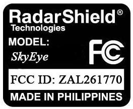
APPLICANT: N7S CORP. FCC ID: ZAL261770 EXTERNAL PHOTOS
Internal Photos
APPLICANT: N7S CORP. FCC ID: ZAL261770 INTERNAL PHOTOS
Test Report
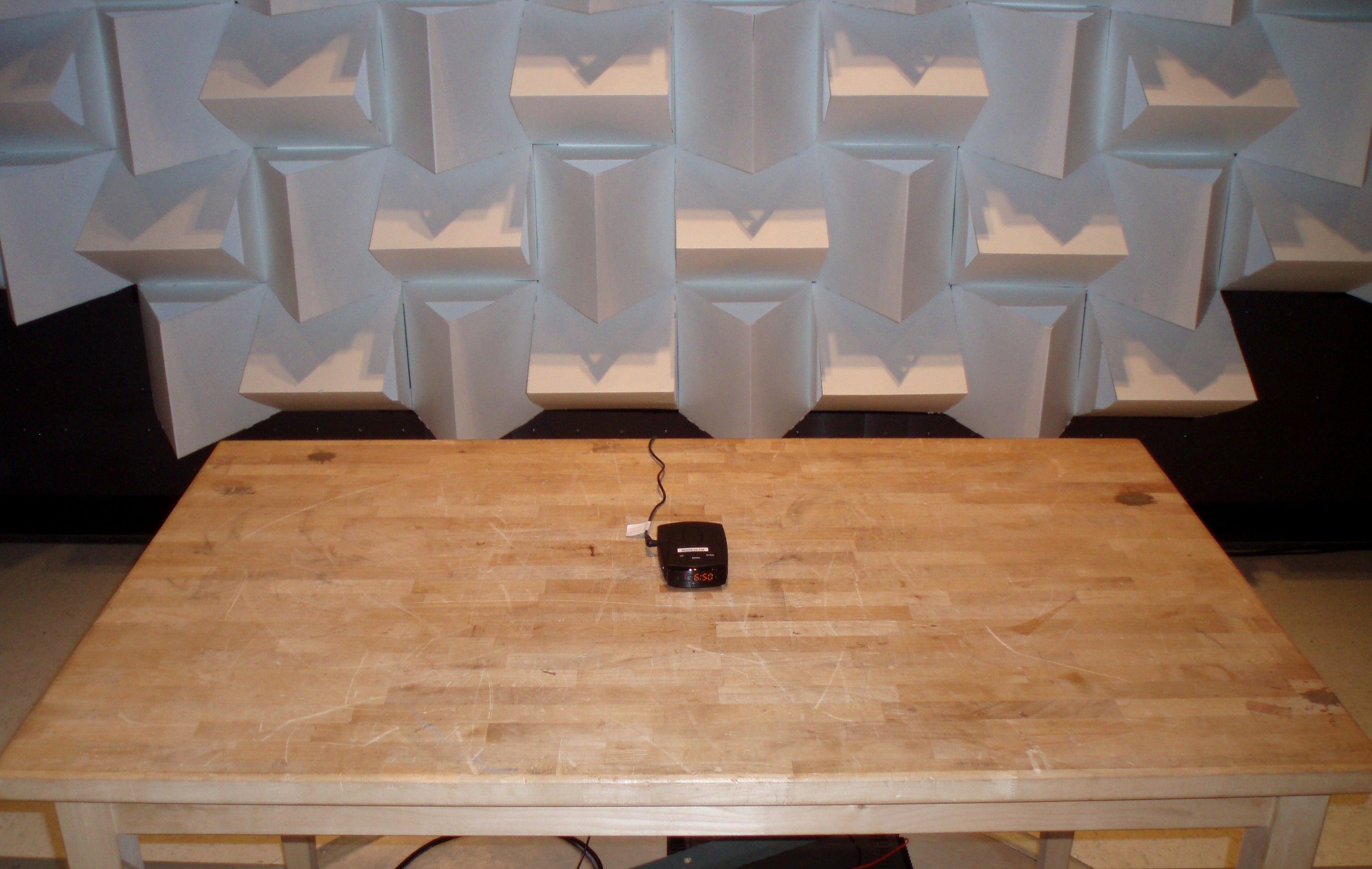
FCC PART 15 RADAR DETECTOR REPORT Applicant N7S CORP. Address 4757 NW 67 AVENUE LAUDERHILL FL USA FCC ID: ZAL261770 Product Description RADAR DETECTOR Date Sample Received 6/3/2011 Date Tested 6/16/2011 Tested By Nam Nguyen Approved By Mario de Aranzeta Report Number 1237UT11TestReport.doc Test Results PASS FAIL THE ATTACHED REPORT SHALL NOT BE REPRODUCED EXCEPT IN FULL WITHOUT THE WRITTEN APPROVAL OF TIMCO ENGINEERING, INC. 849 NW State Road 45 Newberry, Fl 32669 USA Phone: 888.472.2424 or 352.472.5500 Fax: 352.472.2030 Email: [email protected] Website: www.timcoengr.com Certificate # 0955-01 APPLICANT: N7S CORP. FCC ID: ZAL261770 REPORT: N\N7S CORP.\1237UT11\1237UT11TestReport.doc Page 2 of 11 TABLE OF CONTENTS GENERAL REMARKS ............................................................................................................. 3 GENERAL INFORMATION ...................................................................................................... 4 TEST EQUIPMENT LIST ......................................................................................................... 5 TEST PROCEDURES .............................................................................................................. 6 RADIATED SPURIOUS EMISSIONS ........................................................................................ 8 VERTICAL PLOT (PEAK) ......................................................................................................... 9 VERTICAL PLOT (AVERAGE) ................................................................................................ 10 RADIATED EMISSIONS TEST SETUP PHOTO ....................................................................... 11 APPLICANT: N7S CORP. FCC ID: ZAL261770 REPORT: N\N7S CORP.\1237UT11\1237UT11TestReport.doc Page 3 of 11 GENERAL REMARKS The attached report shall not be reproduced except in full without the written permission of Timco Engineering Inc. The test results relate only to the items tested. Summary The device under test does: fulfill the general approval requirements as identified in this test report not fulfill the general approval requirements as identified in this test report Attestations This equipment has been tested in accordance with the standards identified in this test report. To the best of my knowledge and belief, these tests were performed using the measurement procedures described in this report. All instrumentation and accessories used to test products for compliance to the indicated standards are calibrated regularly in accordance with ISO 17025: 2005 requirements. Certificate # 0955-01 I attest that the necessary measurements were made, under my supervision, at: Timco Engineering Inc. 849 NW State Road 45 Newberry, Fl 32669 Authorized Signatory Name: Mario de Aranzeta C.E.T. Compliance Engineer/ Lab. Supervisor Date: 6/16/2011 APPLICANT: N7S CORP. FCC ID: ZAL261770 REPORT: N\N7S CORP.\1237UT11\1237UT11TestReport.doc Page 4 of 11 GENERAL INFORMATION The test results relate only to the items tested. DUT Description RADAR DETECTOR FCC ID ZAL261770 DUT Power Source 110–120Vac/50– 60Hz DC Power Battery Operated Exclusively Test Item Prototype Pre-Production Production Modifications to DUT None Test Standards FCC Part 15, Subpart B, ANSI C63.4-2003 APPLICANT: N7S CORP. FCC ID: ZAL261770 REPORT: N\N7S CORP.\1237UT11\1237UT11TestReport.doc Page 5 of 11 TEST EQUIPMENT LIST Device Manufacturer Model Serial Number Cal/Char Date Due Date 3-Meter Semi- Anechoic Chamber Panashield N/A N/A Listed 3/10/10 3/10/12 AC Voltmeter HP 400FL 2213A14499 CAL 3/23/09 3/23/12 Antenna: Dipole Kit Electro- Metrics TDA-30/1-4 153 CHAR 6/10/09 6/10/12 Frequency Counter HP 5385A 3242A07460 CAL 5/26/09 5/26/12 Hygro- Thermometer Extech 445703 0602 CAL 1/30/09 1/30/12 Modulation Analyzer HP 8901A 3435A06868 CAL 5/26/09 5/26/12 Digital Multimeter Fluke FLUKE-77-3 79510405 CAL 5/18/09 5/18/12 Analyzer Tan Tower Preamplifier HP 8449B-H02 3008A00372 CAL 11/21/09 11/21/11 Analyzer Tan Tower Quasi- Peak Adapter HP 85650A 3303A01690 CAL 11/22/09 11/22/11 Analyzer Tan Tower RF Preselector HP 85685A 3221A01400 CAL 11/21/09 11/21/11 Analyzer Tan Tower Spectrum Analyzer HP 8566B Opt 462 3138A07786 3144A20661 CAL 11/24/09 11/24/11 Temperature Chamber Tenney Engineering TTRC 11717-7 CHAR 4/25/10 4/25/12 APPLICANT: N7S CORP. FCC ID: ZAL261770 REPORT: N\N7S CORP.\1237UT11\1237UT11TestReport.doc Page 6 of 11 TEST PROCEDURES General: This report shall NOT be reproduced except in full without the written approval of TIMCO ENGINEERING, INC. RADIATION INTERFERENCE: Testing was done in accordance with ANSI C63.4-2003. Section 15.35(b) specifies the use of an average detector in this band. In addition, the peak level of an emission shall not exceed the average limit by more than 20 dB using a minimum Resolution Bandwidth (RBW) of 1 MHz and minimum Video Bandwidth (VBW) OF 1 MHz. The following procedure is designed to determine if there are any spurious emissions from the local oscillator within the band of interest along with any additional spurious emissions caused by other circuitry within the device. 1) Determine the frequency of the peak emission: Start Frequency 11.7 GHz Stop Frequency 12.2 GHz RBW equal to or greater than 1 MHz VBW equal to or greater than 1 MHz Detector Function Peak Maximize the emissions with regards to device orientation, antenna polarization, and antenna height. Sweep the band using Max Hold for a minimum of 2 minutes. Record this frequency for measuring the peak emission. In addition record the frequency of other spurious emissions noted. 2) Determine the peak level of the emission: Center Frequency Set to the frequency determined in Step 1 RBW Equal to or greater than 1 MHz VBW Equal to or greater than 1 MHz Detector Function Peak Measure the value of the peak emission using Max Hold for a minimum of 2 minutes. This can be done at zero span or a frequency span where the analyzer does not show a “Measurement Uncalibrated…
Text truncated - open the document above for the full version.
Contact Information
Applicant
Nir Steel(President)
Test Firm
Timco Engineering, Inc.Bruno Clavier
Technical Specifications
| # | Rule Parts | Frequency Range | Power Output |
|---|---|---|---|
| 4 | 15B | 33.40 GHz - 36.00 GHz | - |
Other Applications from N7S Corp.
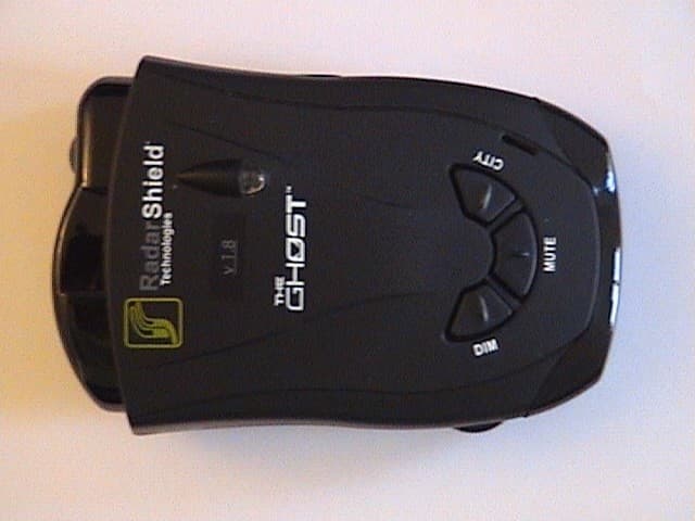
ZAL26770
Feb 23, 2011RADAR DETECTOR
Equipment Class
CRD - Part 15 Radar Detector