ZANEHZPA20ZigBee Communication Daughter Card
EnergyHub, Inc.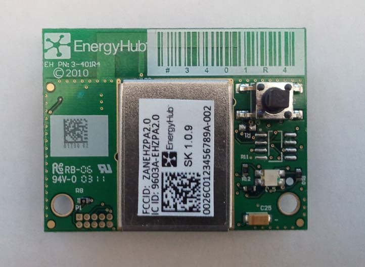
Click to zoom
Application Details
- Equipment Class
- DTS - Digital Transmission System
- Date of Grant
- May 23, 2011
- Application Purpose
- Original Equipment
- Date of Application
- May 18, 2011
- Equipment Note
- ZigBee Communication Daughter Card
- Frequency Range
- 2405.00000000 - 2480.00000000
- Company
- EnergyHub, Inc.
- Country
- United States
Documents & Files
Document Text
Text extracted from the exhibit documents filed with the FCC. Open a document above to read the original.
Users Manual
Doc Title Communication Board Manual Doc Number ENG-SPEC-MNL-1040 Rev 1 Doc Type Product Manual Department Engineering The confidential information contained within this document is the property of EnergyHub, Inc and may not be duplicated, used, disclosed, or distributed without the written consent of EnergyHub, Inc. Page 1 of 6 Communication Board Manual ENG-SPEC-MNL-1040R1 Rev By Date Description 1 TK 5/12/11 Initial Release Doc Title Communication Board Manual Doc Number ENG-SPEC-MNL-1040 Rev 1 Doc Type Product Manual Department Engineering The confidential information contained within this document is the property of EnergyHub, Inc and may not be duplicated, used, disclosed, or distributed without the written consent of EnergyHub, Inc. Page 2 of 6 TABLE OF CONTENTS 1 PURPOSE .................................................................................................................................................................. 3 2 INTRODUCTION ........................................................................................................................................................ 3 3 ELECTRICAL CONNECTOR INTERFACE ........................................................................................................................ 3 4 INDUSTRY COMPLIANCE ........................................................................................................................................... 5 Doc Title Communication Board Manual Doc Number ENG-SPEC-MNL-1040 Rev 1 Doc Type Product Manual Department Engineering The confidential information contained within this document is the property of EnergyHub, Inc and may not be duplicated, used, disclosed, or distributed without the written consent of EnergyHub, Inc. Page 3 of 6 1 Purpose This document serves as the manual for the EnergyHub daughtercard to be used only in EnergyHub devices as specified by this document. 2 Introduction Each EnergyHub peripheral device contains a comm board. This board serves as the communication interface for the EnergyHub system. Each device within the EnergyHub network uses one of these devices to communicate with the Home Base which gathers information about the use of energy in a user’s home. 3 Electrical Connector Interface Connectors P3 and P4 are the main connection from the EH Communications board. The power and signals between the EH communication board and the host interface are carried through this connection. The connectors on the Comm Board are 2mm pitch, 2 row 16 pin receptacle connectors. The Dashboard interface has two 16 pin headers. Figure 3 shows a picture of the connections on the bottom of the communication board. Figure 1- Connectors on the bottom of Communication Module Doc Title Communication Board Manual Doc Number ENG-SPEC-MNL-1040 Rev 1 Doc Type Product Manual Department Engineering The confidential information contained within this document is the property of EnergyHub, Inc and may not be duplicated, used, disclosed, or distributed without the written consent of EnergyHub, Inc. Page 4 of 6 3.1 Connector Pinout P4 P3 1 CLK_OUT PTD4/PULSE1 2 1 CTS2 RTS2 2 3 DGND P3V3 4 3 PTB1/ADC1 PTB0/ADC0 4 5 PTA0 PTA1 6 5 PTB3/ADC3 PTB2/ADC2 6 7 PTC6/MISO PTC7/SS 8 7 PTB5/ADC5 PTB4/ADC4 8 9 PTC4/SCK PTC5/MOSI 10 9 PTB7/ADC7/RTCK PTB6/ADC6 10 11 PTC2/SDA PTC3/SCL 12 11 PTD2 RTS1 12 13 PTC0/TX2 PTC1/RX2 14 13 TX1 PTA3 14 15 RESETB PTD5/PULSE2 16 15 RX1 PTD7 16 Communication Digital/Timing Power Digital/Timing Table 1 - Connector Pinout 3.1 Power The P3V3 is a 3.3V power supply to the board. The maximum available current draw to the daughtercard board is 200mA. 3.2 Serial Communications Interface 3.2.1 UART1 The UART logic high voltage is 3.3V Pin P3-13 for the TX1 pin has a 10K pullup on the host interface Pin P3-16 for the RX1 pin has a 10K pulldown on the host interface The default baud rate is 38400. It can be modified in firmware to adapt to the host module. 3.2.2 UART2 The UART logic high voltage is 3.3V Doc Title Communication Board Manual Doc Number ENG-SPEC-MNL-1040 Rev 1 Doc Type Product Manual Department Engineering The confidential information contained within this document is the property of EnergyHub, Inc and may not be duplicated, used, disclosed, or distributed without the written consent of EnergyHub, Inc. Page 5 of 6 Pin P4-13 for the TX2 pin has a 10K pullup on the host interface Pin P4-14 for the RX2 pin has a 10K pulldown on the host interface CTS2 and RTS2 are active low. The default baud rate is 38400. It can be modified in firmware to adapt to the host module. 3.2.3 I2C The I2C voltage is 3.3V The I2C requires 4.7k Ohm pullups on the host board. 3.2.4 SPI SPI logic voltage is 3.3v Daughter card shall be configured as the slave device. 4 Industry Compliance 4.1 FCC Compliance Statement This device complies with part 15 of the FCC rules. Operation is subject to the fol- lowing two conditions: (1) This device may not cause harmful interference, and (2) this device must accept any interference received, including interference that may cause undesired operation. See instructions if interference to radio or television reception is suspected. Radio and Television Interference This equipment has been tested and found to comply with the limits for a Class B digital device in accordance with the specifications in Part 15 of FCC rules. These specifications are designed to provide reasonable protection against such interference in a residential installation. However, there is no guarantee that interference will not occur in a particular installation. You can determine whether your equipment is causing interference by turning it off. If the interference stops, it was probably caused by the equipment. If your equipment does cause interference to radio or television reception, try to correct the interference by using one or more of the following measures: Change the position of the television or radio antenna until the interference stops. …
Text truncated - open the document above for the full version.
Cover Letter(s)
Professional Testing (EMI), Inc. 1601 FM 1460, Suite B Round Rock, Texas 78664 May 11, 2011 On behalf of EnergyHub, Inc., Professional Testing (EMI), Inc. is seeking a modular approval for the Zigbee Daughter Card. Requirements listed in FCC part 15.212 and Section 3.2.2 of RSS-Gen Issue 3 are addressed below. 1) The device has a RF shield covering the RF generating portion of the circuit board. 2) The external data inputs are buffered with FIFO data buffering. 3) The module is powered from a self contained switching power source that converts AC voltage to 5 VDC. An internal regulator converts 5 VDC to 3.3 VDC. 4) The antenna requirement is satisfied by the use of a PCB plane inverted antenna. 5) The module was tested in a stand-alone configuration, free of an enclosure. 6) A sticker is affixed to the back side of the . The manual contains the explicit directions to label the exterior of the device into which the RADM-ZP is integrated with “Contains FCC ID: ZANEHZPA20”. 7) The Users Manual explains that any modifications may strictly void the certification and a separate approval must be obtained. 8) Emissions are far below the RF Exposure limits. Layne Lueckemeyer
Cover Letter(s)
Date: 5/22/11 Subject: Confidentiality Request for: ZANEHZPA20 Pursuant to FCC 47 CRF 0.457(d) and 0.459 and IC RSP-100, Section 10, the applicant requests that a part of the subject FCC application be held confidential. Type of Confidentiality Requested Exhibit Short Term Permanent Block Diagrams Short Term External Photos Short Term Permanent* i Internal Photos Short Term Permanent Operation Description/Theory of Operation Short Term Permanent Parts List & Placement/BOM Short Term Permanent Tune-Up Procedure Short Term Permanent Schematics Short Term Test Setup Photos Short Term Permanent* User’s Manual EnergyHub Inc has spent substantial effort in developing this product and it is one of the first of its kind in industry. Having the subject information easily available to "competition" would negate the advantage they have achieved by developing this product. Not protecting the details of the design will result in financial hardship. Permanent Confidentiality: The applicant requests the exhibits listed above as permanently confidential be permanently withheld from public review due to materials that contain trade secrets and proprietary information not customarily released to the public. Short-Term Confidentiality: The applicant requests the exhibits selected above as short term confidential be withheld from public view for a period of 180 days from the date of the Grant of Equipment Authorization and prior to marketing. This is to avoid premature release of sensitive information prior to marketing or release of the product to the public. Applicant is also aware that they are responsible to notify ACB in the event information regarding the product or the product is made available to the public. ACB will then release the documents listed above for public disclosure pursuant to FCC Public Notice DA 04-1705. Sincerely, Thomas Kennedy Director of Hardware Development
External Photos
External Photos External Photos (Bottom)
ID Label/Location Info
FCC ID: ZANEHZPA2 0 IC : 9603A - EHZPA20 0026C0123456789A SK 1.0.9 Model:RADM - ZP
ID Label/Location Info
Label Location 12147
Internal Photos
Internal Photos
RF Exposure Info
SAR Waiver Calculation FCC ID: ZANEHZPA20 IC Identifier: 9603A-EHZPA20 PROJECT # DATE RULE 12147-10 May 17, 2011 FCC 2.1093 / 1.1310 COMMENT Center frequency of band utilized to calculate SAR waiver limit. SAR Waiver equation P=60/f (GHz) P=60/2.440=24.6 mW Results Table B Mode Frequency (MHz) Power (dBm) Power (mW) Limit (mW) 2405 -11.13 0.077 24.6 2445 -12.33 0.058 24.6 2480 -11.73 0.067 24.6 Note: According to KDB447498 Mobile and Portable Device RF Exposure Procedures and Equipment Authorization Policies SAR Evaluation not required because output power is ≤ 60/f (GHz) mW Result: Pass
Test Report
1601 North A.W. Grimes Blvd., Suite B Round Rock, TX 78665 e-mail: [email protected] (512) 244-3371 Fax: (512) 244-1846 May 16, 2011 Tom Kennedy EnergyHub, Inc. 232 3rd Street, Suite C201 Brooklyn, NY 11215 Dear Tom: Enclosed is the Wireless Test Report for the Zigbee Daughter Card by EnergyHub, Inc. This report can be used to demonstrate compliance with FCC and IC requirements for wireless devices in the United States and Canada. If you have any questions, please contact me. Sincerely, Jeffrey A. Lenk President Enclosure EnergyHub, Inc. – Zigbee Daughter Card, Wireless Certification Report 12147-10 May 16, 2011 Page 2 of 49 Project 12147-10 EnergyHub, Inc. Zigbee Daughter Card Wireless Certification Report Prepared for: EnergyHub, Inc. 232 3rd Street, Suite C201 Brooklyn, NY 11215 By Professional Testing (EMI), Inc. 1601 N. A.W. Grimes Blvd., Suite B Round Rock, Texas 78665 May 5, 2011 Revised May 16, 2011 Reviewed by Written by Jeffrey A. Lenk President Layne Lueckemeyer Product Development Engineer EnergyHub, Inc. – Zigbee Daughter Card, Wireless Certification Report 12147-10 May 16, 2011 Page 3 of 49 EnergyHub, Inc. – Zigbee Daughter Card, Wireless Certification Report 12147-10 May 16, 2011 Page 4 of 49 Table of Contents Title Page .........................................................................................................................................1 1.0 Introduction..........................................................................................................................6 1.1 Scope................................................................................................................................6 1.2 EUT Description ..............................................................................................................6 1.3 Modifications ...................................................................................................................6 1.4 Test Site ...........................................................................................................................6 1.5 Applicable Documents.....................................................................................................7 2.0 Conducted Emissions Mains Terminal Measurements........................................................8 2.1 Test Procedure .................................................................................................................8 2.2 Test Criteria ...................................................................................................................10 2.3 Test Results ....................................................................................................................10 Table 2.3.3 Conducted Emissions Mains Terminals Test Results – Phase Lead (Line 1) ............12 3.0 Output Power .....................................................................................................................13 3.1 Test Procedure ...............................................................................................................13 3.2 Test Criteria ...................................................................................................................13 3.3 Test Results ....................................................................................................................14 4.0 Occupied Bandwidth..........................................................................................................16 4.1 Test Procedure ...............................................................................................................16 4.2 Test Criteria ...................................................................................................................16 4.3 Test Results ....................................................................................................................16 5.0 Power Spectral Density......................................................................................................26 5.1 Test Procedure ...............................................................................................................26 5.2 Test Criteria and Methodology ......................................................................................26 5.3 Test Results ....................................................................................................................26 6.0 Band Edge Spurious Emissions .........................................................................................30 6.1 Test Procedure ...............................................................................................................30 6.2 Test Criteria ...................................................................................................................30 6.3 Test Results ....................................................................................................................30 7.0 Out of Band Spurious Emissions .......................................................................................34 7.1 Test Procedure ...............................................................................................................34 7.2 Test Criteria ...................................................................................................................34 7.3 Test Results ....................................................................................................................34 Note: This number is the worst case transmit duty cycle based on the 802.15.4 standard. The real application will be much lower. This is the duty cycle attenuation factor to be used for FCC certification........................................................................................................................47 8.0 Antenna Requirements.......................................................................................................48 8.1 Evaluation Procedure .......................................…
Text truncated - open the document above for the full version.
Test Setup Photos
Test Setup Photos
Contact Information
Applicant
Thomas Joseph Kennedy(Director of Hardware Development)
Technical Contact
Professional Testing (EMI), Inc.Layne Lueckemeyer
[email protected]512-244-3371
1601 N. A. W, Grimes, Suite B · Round Rock · United States
Test Firm
Professional TestingRobert McCollough Lenk
Technical Specifications
| # | Rule Parts | Frequency Range | Power Output |
|---|---|---|---|
| 1 | 15C | 2.40 GHz - 2.48 GHz | 77.00 µW |
Other Applications from EnergyHub, Inc.
ZANHBNZP20
May 04, 2011Energy Usage System
Equipment Class
DTS - Digital Transmission System
ZANHBEZP20
May 04, 2011Energy Usage System
Equipment Class
DTS - Digital Transmission System
ZANHBZZP20
May 02, 2011Energy Usage System
Equipment Class
DTS - Digital Transmission System