ZANHBEZP20Energy Usage System
EnergyHub, Inc.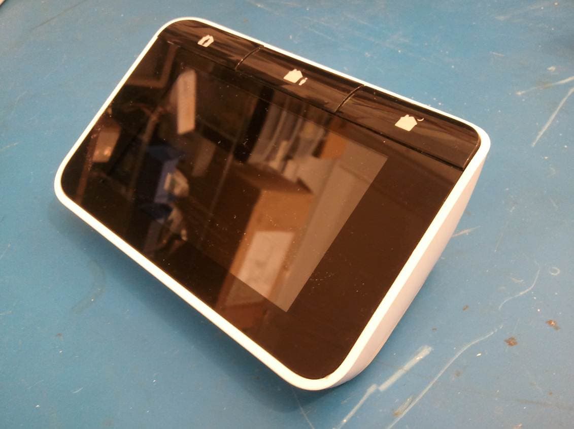
Click to zoom
Application Details
- Equipment Class
- DTS - Digital Transmission System
- Date of Grant
- May 04, 2011
- Application Purpose
- Original Equipment
- Date of Application
- May 02, 2011
- Equipment Note
- Energy Usage System
- Frequency Range
- 2405.00000000 - 2480.00000000
- Company
- EnergyHub, Inc.
- Country
- United States
Documents & Files
Document Text
Text extracted from the exhibit documents filed with the FCC. Open a document above to read the original.
Users Manual
HOME BASE USER GUIDE CHAPTER 4 Safe and Sound Important! Read all the installation instructions and the safety information in Chapter 4 of this guide before you set up your EnergyHub system. Answers to many frequently-asked questions can be found in Chapter 3 of this guide, or online at www.energyhub.com/support. 2 CHAPTER 1 A Few Introductions 4 1.1 EnergyHub and You 1.2 Your Home Base Advantage 1.3 Meeting the Family 1.4 Getting Started 1.5 Connecting to the Internet 1.6 Creating Your EnergyHub Account 1.7 Connecting Appliances to Your Home Base 1.8 Creating Your Modes 1.9 Creating Your Schedule 1.10 Creating Your Vacation Schedule 1.11 Setting Up Your EnergyHub- compatible Thermostat TABLE OF CONTENTS 3 CHAPTER 1 A Few Introductions CHAPTER 3 Ask Away! 32 3.1 The Basics 3.2 Problems You May Encounter 3.3 Frequently Asked Questions CHAPTER 4 Safe and Sound 4.1 Important Safety Information 4.2 Technical Specifications 4.3 Compliance Statement 4.4 Wireless Radio Use 4.5 Industry Canada Statement 4.6 Limited Warranty FIND IT, QUICK 49 CHAPTER 2 Settling In 22 2.1 Viewing Information About Your Energy Usage 2.2 Checking Messages 2.3 Creating Peak Response Settings 2.4 Connecting Your Zigbee-enabled Smart Meter or ERT Meter 2.5 Updating Your Home Base’s Software 2.6 Shutting Down Your Home Base 2.7 Resetting Your Home Base to Its Factory Defaults 4 1.1 ENERGYHUB AND YOU We all want to save energy in our homes, especially the energy we pay for every month. But there are two things we lack: information about how much energy we use, and a system that presents this information in a way we can immediately understand and act on. That’s where your Home Base comes in. It offers you unprecedented control over your home’s energy usage (and bills). It’s quick and easy to set up, and its intuitive touchscreen interface makes managing your ap- pliance and thermostat settings simpler than ever. The Home Base is your first step into the world of EnergyHub. The EnergyHub account you’re about to set up on your Home Base will be accessible anywhere—soon you’ll control your home energy usage via the web, smart phones, and other devices. CHAPTER 1 A Few Introductions 5 NOTE! If your Home Base is unresponsive, you can easily reboot it by pressing the reset button on its underside. 1.2 THE HOME BASE ADVANTAGE Using the Home Base, you can set up your EnergyHub account, view information about your appliances’ power usage, and configure schedules and settings for your appliances and EnergyHub-compatible thermostat. If you have a ZigBee-enabled smart meter or ERT meter, you may be able to receive whole-home energy readings from your utility company. Your Home Base lets you control appliances and thermostats located anywhere in your home from one central location. Important! Using the full range of EnergyHub’s features requires access to a wireless Internet connection in your home. Internet subscription fees may apply. Your Home Base comes with a power adapter. 6 1.3 MEETING THE FAMILY The EnergyHub Home Base thrives on connectivity. Depending on where you get your Home Base, where you live, and what your needs are, you may have a different configuration. Visit www.energyhub.com to learn more about our family of products, and our partners’ products as well. EnergyHub Sockets and Strips Control, measure, and monitor household appliances using the Home Base with EnergyHub Sockets and Strips. EnergyHub Sockets and Strips are the only “smart” sockets and power strips your Home Base can communicate with and control. EnergyHub-compatible Thermostats Program your EnergyHub-compatible thermostat from your Home Base to save even more. 7 CHAPTER 1 A Few Introductions EnergyHub Heavy Duty Controller Control heavy-duty appliances such as pool pumps, water heaters, and clothes dryers from your Home Base with the EnergyHub Heavy Duty Controller. The EnergyHub Heavy Duty Controller requires installation by a qualified electrician or utility provider. Visit www.energyhub.com for more information. ZigBee-enabled smart meter or ERT meter Some utility companies offer ZigBee-enabled smart meter or ERT meter service. Connecting your home’s EnergyHub system to a smart meter or ERT meter may enable your utility company to provide your Home Base with whole-home energy readings, messages, alerts, and real-time pricing information. Contact your utility company directly to find out if it offers smart meter or ERT meter capability, or check online at www.energyhub.com/smartmeter for additional information. 8 1.4 GETTING STARTED At the end of this fast and easy process you will be able to control your thermostat and appliances from your Home Base, or anywhere you have access to the Internet. Let the savings begin! Find a central and convenient place for your Home Base, such as on a kitchen counter or coffee table, or near the door you usually leave home from. Important! Your Home Base must remain plugged in at all times in order to effectively monitor and control your energy usage. Connect the power adapter to the jack located on the bottom of the Home Base, and then plug the power adapter into a standard electrical outlet. Your Home Base will turn on automatically after a few moments. Since this is the first time you’ve powered up your Home Base, it will ask you to review the EnergyHub License Agreement. To scroll to the end of the agreement, use your finger to drag the bar on the right side of the screen. 9 CHAPTER 1 A Few Introductions Done? OK. What you see now is the landing screen. The landing screen gathers the information you need most to make wise energy decisions, and presents it to you in a clear and easy-to-understand way. Once your Home Base is up and running, you’re going to love checking this screen to find out how much money and energy you’re saving. But first we have a little—just a little!—more work to do. 10 1.5 CONNECTING TO THE INTERNET Your Home Base wants to communicate with the Internet over your home’s wireless Internet …
Text truncated - open the document above for the full version.
External Photos
External Photos
ID Label/Location Info
Model No.: DB2-EZP Rating: 5 VDC 1500 mA 60 HZ Date: XXXX Serial No.: XXXXXXXXXXXXXXX MAC ID: XXXXXXXXXXXXXXX ZIGBEE MAC ID: XXXXXXXXXXXXXXX This device complies with part 15 FCC rules. Operation is subject to the following two conditions: (1) this device may not cause harmful interference (2) this device must accept any inter- ference received including interference that may cause undesired operation For indoor use only. Pour une utilisation en intérieur. FCC ID:ZANHBEZP20 IC ID:9603A-HBEZP20 Brooklyn, New York Made in China Patent Pending. Model No.: DB2-EZP-HON Rating: 5 VDC 1500 mA 60 HZ Date: XXXX Serial No.: XXXXXXXXXXXXXXX MAC ID: XXXXXXXXXXXXXXX ZIGBEE MAC ID: XXXXXXXXXXXXXXX Golden Valley, Minnesota 55422 customer.honeywell.com 1-800-468-1502 Patent Pending. 50061873-001 Rev. A Made in China/Fabriqué en Chine This device complies with part 15 FCC rules. Operation is subject to the following two conditions: (1) this device may not cause harmful interference (2) this device must accept any inter- ference received including interference that may cause undesired operation For indoor use only. Pour une utilisation en intérieur. FCC ID:ZANHBEZP20 IC ID:9603A-HBEZP20
Internal Photos
Internal Photos
RF Exposure Info
Project 12145-10 Prepared for: EnergyHub, Inc. 232 3rd Street, Suite C201 Brooklyn, NY 11215 By Professional Testing (EMI), Inc. 1601 N. A.W. Grimes Blvd., Suite B Round Rock, Texas 78665 April 18, 2011 MPE / RF Exposure Report HomeBase FCC ID: ZANHBZZP20, ZANHBEZP20, ZANHBNZP20 IC Identifier: 9603A-HBZZP20, 9603A-HBEZP20, 9603A-HBNZP20 12145-10 Page 2 of 6 Table of Contents Title Page ........................................................................................................................................1 Table of Contents ...........................................................................................................................2 Certificate of Compliance..............................................................................................................4 1.0 MPE Prediction ...................................................................................................................4 1.1 Evaluation Procedure .......................................................................................................4 1.2 Evaluation Criteria ...........................................................................................................4 NOTICE: (1) This Report must not be used to claim product endorsement, by NVLAP, NIST, the FCC or any other Agency. This report also does not warrant certification by NVLAP or NIST. (2) This report shall not be reproduced except in full, without the written approval of Professional Testing (EMI), Inc. (3) The significance of this report is dependent on the representative character of the test sample submitted for evaluation and the results apply only in reference to the sample tested. The manufacturer must continuously implement the changes shown herein to attain and maintain the required degree of compliance. 12145-10 Page 3 of 6 Applicant: EnergyHub, Inc. Applicant’s Address: 232 3rd Street, Suite C201 Brooklyn, NY 11215 FCC ID: ZANHBZZP20, ZANHBEZP20, ZANHBNZP20 IC Number: 9603A-HBZZP20, 9603A-HBEZP20, 9603A-HBNZP20 Project Number: 12145-10 Test Dates: February 16, 22, 23, March 7, 11, 14, 15, 2011 I, Layne Lueckemeyer, for Professional Testing (EMI), Inc., being familiar with the FCC rules and test procedures have reviewed the test setup, measured data and this report. I believe them to be true and accurate. Layne Lueckemeyer Product Development Engineer This report has been reviewed and accepted by EnergyHub, Inc. The undersigned is responsible for ensuring that this device will continue to comply with the FCC and IC rules. 12145-10 Page 4 of 6 1.0 MPE Prediction Prediction of MPE limit at a given distance was made by using equation from page 18 of OET Bulletin 65, Edition 97-01. In order to prove that SAR is not required we used the combined MPE calculation of the Wi-Fi 802.11b, 802.11g, 802.11n device and the Zigbee radios. The data is contained in the worksheet below. 1.1 Evaluation Procedure S=PG/4 R² Where: S = power density P= power input to antenna G = power gain of the antenna in the direction of interest relative to an isotropic radiator R = distance to the center of radiation of the antenna 1.2 Evaluation Criteria MPE limit for uncontrolled exposure at prediction frequency (mW/cm²): 1.0 12145-10 Page 5 of 6 MPE Prediction Calculation PROJECT # DATE RULE DISTANCE ANTENNA RBW VBW DETECTOR 12145-10 April 18, 2011 15.247 N/A N/A N/A N/A N/A Calculations S=PG/4 R² Where: S = power density P= power input to antenna G = power gain of the antenna in the direction of interest relative to an isotropic radiator R = distance to the center of radiation of the antenna MPE B Mode Transmitter Frequency (MHz) Peak Output Power (dBm) Peak Output Power (mW) Prediction Distance (cm) Max Antenna Gain (dBi) Max Antenna Gain (numeric) Power Density at 20.0 cm (mW/cm²) 2412 2.71 1.867 20 2.0 1.585 .00059 MPE G Mode Transmitter Frequency (MHz) Peak Output Power (dBm) Peak Output Power (mW) Prediction Distance (cm) Max Antenna Gain (dBi) Max Antenna Gain (numeric) Power Density at 20.0 cm (mW/cm²) 2412 -9.85 0.103 20 2.0 1.585 .00003 MPE N Mode Transmitter Frequency (MHz) Peak Output Power (dBm) Peak Output Power (mW) Prediction Distance (cm) Max Antenna Gain (dBi) Max Antenna Gain (numeric) Power Density at 20.0 cm (mW/cm²) 2412 -0.42 0.908 20 2.0 1.585 .00029 MPE HAN Zigbee Radio Transmitter Frequency (MHz) Peak Output Power (dBm) Peak Output Power (mW) Prediction Distance (cm) Max Antenna Gain (dBi) Max Antenna Gain (numeric) Power Density at 20.0 cm (mW/cm²) 2405 -0.93 0.807 20 2.0 1.585 .00025 12145-10 Page 6 of 6 MPE Meter Zigbee Radio Transmitter Frequency (MHz) Peak Output Power (dBm) Peak Output Power (mW) Prediction Distance (cm) Max Antenna Gain (dBi) Max Antenna Gain (numeric) Power Density at 20.0 cm (mW/cm²) 2405 -4.15 0.385 20 2.0 1.585 .00012 NOTE: Antenna Gain is estimated worst case scenario. .00059 + .00003 + .00029 + .00025 + .00012 = .00128 mW/cm² .00128 mW/cm² < 1.0 mW/cm² Result = Pass
Test Report
1601 North A.W. Grimes Blvd., Suite B Round Rock, TX 78665 e-mail: [email protected] (512) 244-3371 Fax: (512) 244-1846 April 26, 2011 Tom Kennedy EnergyHub, Inc. 232 3rd Street, Suite C201 Brooklyn, NY 11215 Dear Tom: Enclosed is the Wireless Test Report for the HomeBase by EnergyHub, Inc. This report can be used to demonstrate compliance with FCC and IC requirements for wireless devices in the United States and Canada. If you have any questions, please contact me. Sincerely, Jeffrey A. Lenk President Enclosure EnergyHub, Inc. – HomeBase, Wireless Certification Report 12145-10 April 26, 2011 Page 2 of 132 Project 12145-10 EnergyHub, Inc. HomeBase Wireless Certification Report Prepared for: EnergyHub, Inc. 232 3rd Street, Suite C201 Brooklyn, NY 11215 By Professional Testing (EMI), Inc. 1601 N. A.W. Grimes Blvd., Suite B Round Rock, Texas 78665 April 26, 2011 Revised April 27, 2011 Reviewed by Written by Jeffrey A. Lenk President Layne Lueckemeyer Product Development Engineer EnergyHub, Inc. – HomeBase, Wireless Certification Report 12145-10 April 26, 2011 Page 3 of 132 Table of Contents Title Page .........................................................................................................................................1 ..........................................................................................................................................................5 1.0 Introduction..........................................................................................................................6 1.1 Scope................................................................................................................................6 1.2 EUT Description ..............................................................................................................6 1.3 Modifications ...................................................................................................................6 1.4 Test Site ...........................................................................................................................6 1.5 Applicable Documents.....................................................................................................7 2.0 Power Line Conducted Emissions .......................................................................................8 2.1 Test Procedure .................................................................................................................8 2.2 Test Criteria .....................................................................................................................9 2.3 Test Results ......................................................................................................................9 3.0 Output Power .....................................................................................................................22 3.1 Test Procedure ...............................................................................................................22 3.2 Test Criteria and Methodology ......................................................................................22 3.3 Test Results ....................................................................................................................23 4.0 Occupied Bandwidth..........................................................................................................28 4.1 Test Procedure ...............................................................................................................28 4.2 Test Criteria ...................................................................................................................28 4.3 Test Results ....................................................................................................................28 5.0 Power Spectral Density......................................................................................................59 5.1 Test Procedure ...............................................................................................................59 5.2 Test Criteria and Methodology ......................................................................................59 5.3 Test Results ....................................................................................................................59 6.0 Band Edge Spurious Emissions .........................................................................................75 6.1 Test Procedure ...............................................................................................................75 6.2 Test Criteria ...................................................................................................................75 6.3 Test Results ....................................................................................................................75 7.0 Out of Band Spurious Emissions .......................................................................................91 7.1 Test Procedure ...............................................................................................................91 7.2 Test Criteria ...................................................................................................................91 7.3 Test Results ....................................................................................................................91 8.0 Antenna Requirements.....................................................................................................131 8.1 Evaluation Procedure ...................................................................................................131 8.2 Evaluation Criteria .......................................................................................................131 8.3 Evaluation Results .......................................................................................................131 End of Report ..................................................................…
Text truncated - open the document above for the full version.
Test Setup Photos
Test Setup Photos 12145
Contact Information
Applicant
Thomas Joseph Kennedy(Director of Hardware Development)
Technical Contact
Professional TestingLayne Lueckemeyer
[email protected]512-244-3371
1601 North A.W. Grimes · Round Rock · United States
Test Firm
Professional TestingRobert McCollough Lenk
Technical Specifications
| # | Rule Parts | Frequency Range | Power Output |
|---|---|---|---|
| 1 | 15C | 2.40 GHz - 2.48 GHz | 1.87 mW |
Other Applications from EnergyHub, Inc.
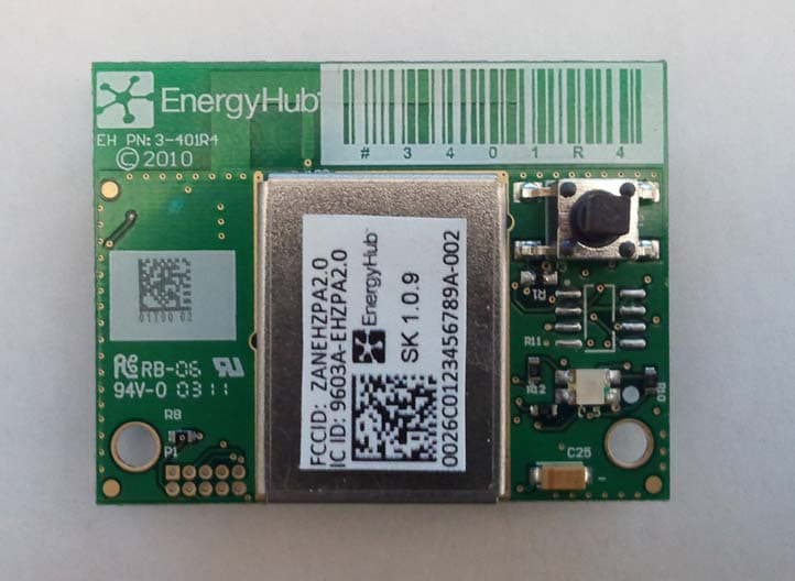
ZANEHZPA20
May 23, 2011ZigBee Communication Daughter Card
Equipment Class
DTS - Digital Transmission System
ZANHBNZP20
May 04, 2011Energy Usage System
Equipment Class
DTS - Digital Transmission System
ZANHBZZP20
May 02, 2011Energy Usage System
Equipment Class
DTS - Digital Transmission System