ZBM-SIP1Stages indoor Power Meter
Foundation Fitness LLC
Click to zoom
Application Details
- Equipment Class
- DTS - Digital Transmission System
- Date of Grant
- Apr 15, 2015
- Application Purpose
- Original Equipment
- Date of Application
- Apr 15, 2015
- Equipment Note
- Stages indoor Power Meter
- Frequency Range
- 2457.00000000 - 2457.00000000
- Company
- Foundation Fitness LLC
- Country
- United States
Documents & Files
Document Text
Text extracted from the exhibit documents filed with the FCC. Open a document above to read the original.
Users Manual
SIP1 Stages Indoor Cycling LLC ® www.stagesindoorcycling.c om [email protected] om 1-800-717-8076 Sales, Accounting and Administrative ,Tech. Support: 1732 NW Quimby, St e 250, Portland, OR 97209 USA Design, Manufacturing, and War ehouse: 3090 Ster ling Cir, Ste 102, Boulder, CO 80301 USA • Batt eries AA x 2 – service life, approximately 2000 hours of riding time • Wir eless transmission: 2.4GHz, ANT+™ and Bluetooth® Smart (BTLE 4.0) • Accuracy: +/-2.5% of measured power • Power measurement range: (watts): 0 – 2500 • Cadence range (RPM): 20-220 • Water resistance rating: IPX7 This product is ANT+ cerd and complies with the following sped ANT+ Device Pro : www.thisisant.com/directory 2 3 1 2 3 4 4 52 - 57 Nm (38 - 42 lb-ft) 8MM L 56 7 8 Fig 2 ANT+ ID # ANT+ ID # ANT+ ID # ANT+ ID # SERIAL # Fig 1 5 6 Pairing the power meter The power meter must be connected or “paired” to the Stages SIC1 display console or cycle computer (c ollectively ref er red to as display units) according to the manufacturer’s instructions. Each power meter has a unique ANT+ device ID. During the pairing process the applicable device ID is recorded by the display and will be used to communicate with the corresponding power meter . The ANT+ ID number is prin ted in the locations shown in FIG 1 and also supplied with the documenta tion. Once paired to the power meter , ride data (Watts and RPM) will be tr ansmitted fr om the power meter to the display unit. Other important functions such as resetting the power meter’s zero o set will also be enabled through the display unit. The ANT+ is permanently assigned to the power meter and is not a ected by changing the power meter batt ery. When Pairing to a Stages SIC1 Console: Ensure the power meter has fully charged AA batt eries p roperly installed. Rotate the crank arm one time to ensure the power meter is awake. Follow the instructions in the Stages console user guide for pairing the power meter to the console. When Pairing to Another Type of Compatible ANT+ Display: Ensure the power meter has fully charged AA batt eries properly installed. Rotate the cr ank ar m one time to ensure the power meter is awake and ready to communicate. Follow the ANT+ device manufacturer’s instructions for pairing a power meter to the display unit. The procedures may var y between manufacturers. Zero O set Calibration The zero o set calibration is an important feature of the power meter that resets the zero o set value for the power meter sensors. There are physical and environmental conditions that may a ect the zero o set value and there are methods both manual and automatic that will adjust this value to accommodate for the changing physical and environmental condition. The zero o set of the power meter is essentially the sensor reading or values measured when the power meter has no pedaling load (t orque) applied. The act of calibrating the zero o set causes the power meter to measure the value at zer o load and then records this value as the baseline for power measurement. 7 How to calibrate Calibrating the zero o set is a function controlled by the Stages SIC1 display console, or cycle computer (display units) paired to the power meter . Please note that some device manufacturers refer to the step of resetting the zero o set as “calibration”. When paired to a Stages SIC1 display console or other compatible ANT+ cycle computer, the power meter and display units ar e in two-way communication. The display unit will send a command to the power meter to calibrate the zero o set value and in some cases the resulting zero o set value will be sent back fr om the power meter to the display unit and be shown on the screen. Please note the displayed zero o set value will NOT be zero but rather a number that corresponds to the measurement taken by the sensor. The display units will also indicate if the procedure was success- ful or failed. Before attempting to calibrate the zero o set value of the power meter, ensure that a working batt ery is in use and the pedal is attached. Rotate the power meter one revolution to ensure the power meter is awake and ready to communicate. The left cr ank ar m with power meter MUST be positioned straight down (6 o’clock position) and ensure there is no load on the pedals and the bike is stable. See FIG 2 for a visual ref er ence. If the left cr ank ar m is not straight down the reset procedure for zer o o set will fail. To calibrate the zero o set of the power meter, follow the instructions supplied with Stages SIC1 display console or ANT+ display console being used with the power meter. Loads applied while pedaling will then be measured as torque and used by the sensor to determine power in Watts. The zero o set value can be a ected by the installation of the crank arm and the tightening of the securing hardwar e. The torque applied to the securing hardwar e can impart some strain in to the cr ank mater ial that is easily accounted for by manually calibrating the zero o set. Any time the power meter is removed from the bike and reinstalled, the zero o set should be calibrated. 8 Troubleshooting If no power (watts) or cadence (RPM) signal is being received by your compatible display unit when riding the bike, please it ems: Con rm that working AA batteries are properly installed in the power meter according to assembly steps 1-4 on page 3. 2. Ride the bike with a pedaling cadence of greater than 20 RPM. Your power meter will not send cadence or wattage to the display unless a true pedaling force is applied. I f you pedal the bike by hand the display will not show cadence or watts — this is not a problem — as soon as you ride the bike you will see your cadence and power values displayed. 3. Ensure that the power meter has been successfully paired to the display 4. For further assistance with Troubleshooting, F AQs, videos and useful tips, please visit our website. 1. Maintenance and cleaning The only it ems of the power meter that can be serviced by the…
Text truncated - open the document above for the full version.
Users Manual
SIP1 Stages Indoor Cycling LLC ® www.stagesindoorcycling.c om [email protected] om 1-800-717-8076 Sales, Accounting and Administrative ,Tech. Support: 1732 NW Quimby, St e 250, Portland, OR 97209 USA Design, Manufacturing, and War ehouse: 3090 Ster ling Cir, Ste 102, Boulder, CO 80301 USA • Batt eries AA x 2 – service life, approximately 2000 hours of riding time • Wir eless transmission: 2.4GHz, ANT+™ and Bluetooth® Smart (BTLE 4.0) • Accuracy: +/-2.5% of measured power • Power measurement range: (watts): 0 – 2500 • Cadence range (RPM): 20-220 • Water resistance rating: IPX7 This product is ANT+ cerd and complies with the following sped ANT+ Device Pro : www.thisisant.com/directory 2 3 1 2 3 4 4 52 - 57 Nm (38 - 42 lb-ft) 8MM L 56 7 8 Fig 2 ANT+ ID # ANT+ ID # ANT+ ID # ANT+ ID # SERIAL # Fig 1 5 6 Pairing the power meter The power meter must be connected or “paired” to the Stages SIC1 display console or cycle computer (c ollectively ref er red to as display units) according to the manufacturer’s instructions. Each power meter has a unique ANT+ device ID. During the pairing process the applicable device ID is recorded by the display and will be used to communicate with the corresponding power meter . The ANT+ ID number is prin ted in the locations shown in FIG 1 and also supplied with the documenta tion. Once paired to the power meter , ride data (Watts and RPM) will be tr ansmitted fr om the power meter to the display unit. Other important functions such as resetting the power meter’s zero o set will also be enabled through the display unit. The ANT+ is permanently assigned to the power meter and is not a ected by changing the power meter batt ery. When Pairing to a Stages SIC1 Console: Ensure the power meter has fully charged AA batt eries p roperly installed. Rotate the crank arm one time to ensure the power meter is awake. Follow the instructions in the Stages console user guide for pairing the power meter to the console. When Pairing to Another Type of Compatible ANT+ Display: Ensure the power meter has fully charged AA batt eries properly installed. Rotate the cr ank ar m one time to ensure the power meter is awake and ready to communicate. Follow the ANT+ device manufacturer’s instructions for pairing a power meter to the display unit. The procedures may var y between manufacturers. Zero O set Calibration The zero o set calibration is an important feature of the power meter that resets the zero o set value for the power meter sensors. There are physical and environmental conditions that may a ect the zero o set value and there are methods both manual and automatic that will adjust this value to accommodate for the changing physical and environmental condition. The zero o set of the power meter is essentially the sensor reading or values measured when the power meter has no pedaling load (t orque) applied. The act of calibrating the zero o set causes the power meter to measure the value at zer o load and then records this value as the baseline for power measurement. 7 How to calibrate Calibrating the zero o set is a function controlled by the Stages SIC1 display console, or cycle computer (display units) paired to the power meter . Please note that some device manufacturers refer to the step of resetting the zero o set as “calibration”. When paired to a Stages SIC1 display console or other compatible ANT+ cycle computer, the power meter and display units ar e in two-way communication. The display unit will send a command to the power meter to calibrate the zero o set value and in some cases the resulting zero o set value will be sent back fr om the power meter to the display unit and be shown on the screen. Please note the displayed zero o set value will NOT be zero but rather a number that corresponds to the measurement taken by the sensor. The display units will also indicate if the procedure was success- ful or failed. Before attempting to calibrate the zero o set value of the power meter, ensure that a working batt ery is in use and the pedal is attached. Rotate the power meter one revolution to ensure the power meter is awake and ready to communicate. The left cr ank ar m with power meter MUST be positioned straight down (6 o’clock position) and ensure there is no load on the pedals and the bike is stable. See FIG 2 for a visual ref er ence. If the left cr ank ar m is not straight down the reset procedure for zer o o set will fail. To calibrate the zero o set of the power meter, follow the instructions supplied with Stages SIC1 display console or ANT+ display console being used with the power meter. Loads applied while pedaling will then be measured as torque and used by the sensor to determine power in Watts. The zero o set value can be a ected by the installation of the crank arm and the tightening of the securing hardwar e. The torque applied to the securing hardwar e can impart some strain in to the cr ank mater ial that is easily accounted for by manually calibrating the zero o set. Any time the power meter is removed from the bike and reinstalled, the zero o set should be calibrated. 8 Troubleshooting If no power (watts) or cadence (RPM) signal is being received by your compatible display unit when riding the bike, please it ems: Con rm that working AA batteries are properly installed in the power meter according to assembly steps 1-4 on page 3. 2. Ride the bike with a pedaling cadence of greater than 20 RPM. Your power meter will not send cadence or wattage to the display unless a true pedaling force is applied. I f you pedal the bike by hand the display will not show cadence or watts — this is not a problem — as soon as you ride the bike you will see your cadence and power values displayed. 3. Ensure that the power meter has been successfully paired to the display 4. For further assistance with Troubleshooting, F AQs, videos and useful tips, please visit our website. 1. Maintenance and cleaning The only it ems of the power meter that can be serviced by the…
Text truncated - open the document above for the full version.
Cover Letter(s)
Foundation Fitness LLC 1732 NW Quimby Ste 250 Portland Oregon 97209 United States Federal Communications Commission Authorization and Evaluation Division Equipment Authorization Branch 7435 Oakland Mills Road Columbia, MD 21046 Date: 2015-03-25 To whom it may concern: We, the undersigned, hereby authorize Worldwide Testing Services (Taiwan) Co., Ltd to act on our behalf in all matters relating to applications for equipment authorization FCC ID: ZBM-SIP1 including the signing of all documents related to these matters. Any and all acts carried out by Worldwide Testing Services (Taiwan) Co., Ltd on our behalf shall have the same effect as acts of our own. We also hereby certify that no party to this application is subject to a denial of benefits, including FCC benefits, pursuant to Section 5301 of the Anti-Drug Abuse Act of 1988, 21 U.S.C. 862. Sincerely, Signature Name: Douglas Crawford Title: V.P. Product Development Company: Foundation Fitness LLC
Cover Letter(s)
Foundation Fitness LLC 1732 NW Quimby Ste 250 Portland Oregon 97209 United States Federal Communications Commission Equipment Authorization Branch 7435 Oakland Mills Road Columbia, MD 21046 Date: 2015-03-30 Request for Long-Term Confidentiality Company name: Foundation Fitness LLC FCC ID: ZBM-SIP1 FCC Part 15 Certification To whom it may concern: In accordance with §§ 0.457(d) and 0.459 of CFR 47, Company name hereby requests Long-Term confidentiality of all Block Diagrams, Schematics, Operational Description attachments for the subject application. These documents contain detailed system and equipment description and related information about the product which Foundation Fitness LLC considers to be proprietary, confidential and a custom design and otherwise would not release to the general public. Since the design is a basis from which future technological products will evolve, Foundation Fitness LLC considers that this information would be of benefit to its competitors and that the disclosure of the information in these documents would give competitors an unfair advantage in the market. Sincerely, Signature Name: Doug Crawford Title: V.P. Product Development Company: Foundation Fitness LLC
Cover Letter(s)
Foundation Fitness LLC 1732 NW Quimby Ste 250 Portland Oregon 97209 United States Federal Communications Commission Authorization and Evaluation Division Equipment Authorization Branch 7435 Oakland Mills Road Columbia, MD 21046 Date: 2015-03-25 To whom it may concern: We, the undersigned, hereby authorize Worldwide Testing Services (Taiwan) Co., Ltd to act on our behalf in all matters relating to applications for equipment authorization FCC ID: ZBM-SIP1 including the signing of all documents related to these matters. Any and all acts carried out by Worldwide Testing Services (Taiwan) Co., Ltd on our behalf shall have the same effect as acts of our own. We also hereby certify that no party to this application is subject to a denial of benefits, including FCC benefits, pursuant to Section 5301 of the Anti-Drug Abuse Act of 1988, 21 U.S.C. 862. Sincerely, Signature Name: Douglas Crawford Title: V.P. Product Development Company: Foundation Fitness LLC
Cover Letter(s)
Foundation Fitness LLC 1732 NW Quimby Ste 250 Portland Oregon 97209 United States Federal Communications Commission Equipment Authorization Branch 7435 Oakland Mills Road Columbia, MD 21046 Date: 2015-03-30 Request for Long-Term Confidentiality Company name: Foundation Fitness LLC FCC ID: ZBM-SIP1 FCC Part 15 Certification To whom it may concern: In accordance with §§ 0.457(d) and 0.459 of CFR 47, Company name hereby requests Long-Term confidentiality of all Block Diagrams, Schematics, Operational Description attachments for the subject application. These documents contain detailed system and equipment description and related information about the product which Foundation Fitness LLC considers to be proprietary, confidential and a custom design and otherwise would not release to the general public. Since the design is a basis from which future technological products will evolve, Foundation Fitness LLC considers that this information would be of benefit to its competitors and that the disclosure of the information in these documents would give competitors an unfair advantage in the market. Sincerely, Signature Name: Doug Crawford Title: V.P. Product Development Company: Foundation Fitness LLC
External Photos
Registration number: W6M21503-14861-C-1 FCC ID: ZBM-SIP1 Worldwide Testing Services(Taiwan) Co., Ltd. Appendix Page 1 of 12 External Photos Registration number: W6M21503-14861-C-1 FCC ID: ZBM-SIP1 Worldwide Testing Services(Taiwan) Co., Ltd. Appendix Page 2 of 12 Registration number: W6M21503-14861-C-1 FCC ID: ZBM-SIP1 Worldwide Testing Services(Taiwan) Co., Ltd. Appendix Page 3 of 12 Registration number: W6M21503-14861-C-1 FCC ID: ZBM-SIP1 Worldwide Testing Services(Taiwan) Co., Ltd. Appendix Page 4 of 12 Registration number: W6M21503-14861-C-1 FCC ID: ZBM-SIP1 Worldwide Testing Services(Taiwan) Co., Ltd. Appendix Page 5 of 12 Registration number: W6M21503-14861-C-1 FCC ID: ZBM-SIP1 Worldwide Testing Services(Taiwan) Co., Ltd. Appendix Page 6 of 12
External Photos
Registration number: W6M21503-14861-C-1 FCC ID: ZBM-SIP1 Worldwide Testing Services(Taiwan) Co., Ltd. Appendix Page 1 of 12 External Photos Registration number: W6M21503-14861-C-1 FCC ID: ZBM-SIP1 Worldwide Testing Services(Taiwan) Co., Ltd. Appendix Page 2 of 12 Registration number: W6M21503-14861-C-1 FCC ID: ZBM-SIP1 Worldwide Testing Services(Taiwan) Co., Ltd. Appendix Page 3 of 12 Registration number: W6M21503-14861-C-1 FCC ID: ZBM-SIP1 Worldwide Testing Services(Taiwan) Co., Ltd. Appendix Page 4 of 12 Registration number: W6M21503-14861-C-1 FCC ID: ZBM-SIP1 Worldwide Testing Services(Taiwan) Co., Ltd. Appendix Page 5 of 12 Registration number: W6M21503-14861-C-1 FCC ID: ZBM-SIP1 Worldwide Testing Services(Taiwan) Co., Ltd. Appendix Page 6 of 12
ID Label/Location Info
FCC ID: ZBM-SIP1
ID Label/Location Info
FCC ID: ZBM-SIP1
Internal Photos
Registration number: W6M21503-14861-C-1 FCC ID: ZBM-SIP1 Worldwide Testing Services(Taiwan) Co., Ltd. Appendix Page 7 of 12 Internal Photos Registration number: W6M21503-14861-C-1 FCC ID: ZBM-SIP1 Worldwide Testing Services(Taiwan) Co., Ltd. Appendix Page 8 of 12 Registration number: W6M21503-14861-C-1 FCC ID: ZBM-SIP1 Worldwide Testing Services(Taiwan) Co., Ltd. Appendix Page 9 of 12 Registration number: W6M21503-14861-C-1 FCC ID: ZBM-SIP1 Worldwide Testing Services(Taiwan) Co., Ltd. Appendix Page 10 of 12 Registration number: W6M21503-14861-C-1 FCC ID: ZBM-SIP1 Worldwide Testing Services(Taiwan) Co., Ltd. Appendix Page 11 of 12
Internal Photos
Registration number: W6M21503-14861-C-1 FCC ID: ZBM-SIP1 Worldwide Testing Services(Taiwan) Co., Ltd. Appendix Page 7 of 12 Internal Photos Registration number: W6M21503-14861-C-1 FCC ID: ZBM-SIP1 Worldwide Testing Services(Taiwan) Co., Ltd. Appendix Page 8 of 12 Registration number: W6M21503-14861-C-1 FCC ID: ZBM-SIP1 Worldwide Testing Services(Taiwan) Co., Ltd. Appendix Page 9 of 12 Registration number: W6M21503-14861-C-1 FCC ID: ZBM-SIP1 Worldwide Testing Services(Taiwan) Co., Ltd. Appendix Page 10 of 12 Registration number: W6M21503-14861-C-1 FCC ID: ZBM-SIP1 Worldwide Testing Services(Taiwan) Co., Ltd. Appendix Page 11 of 12
RF Exposure Info
Foundation Fitness LLC 1732 NW Quimby Ste 250 Portland Oregon 97209 United States Federal Communications Commission Authorization and Evaluation Division Equipment Authorization Branch 7435 Oakland Mills Road Columbia, MD 21046 Applicant’s declaration concerning RF Radiation Exposure We hereby indicate that the product Product description: Stages Indoor Power Meter Model No: SIP1 The equipment complies with FCC RF radiation exposure limits set forth for an uncontrolled environment. The integral antennas used for this transmitter must not be co-located or operating in conjunction with any other antenna or transmitter within the host device. A safety statement concerning minimum separation distances from enclosure of the Product : Stages Indoor Power Meter will be integrated in the user’s manual to provide end-users with transmitter operating conditions for satisfying RF exposure compliance. The appropriate information can be drawn from the test report no: W6M21503-14861-C-1 and the accompanying calculations. Company: Foundation Fitness LLC Address: 1732 NW Quimby Ste 250 Portland Oregon 97209 United States Date: 2015-03-25 Signature Registration number: W6M21503-14861-C-1 FCC ID: ZBM-SIP1 Worldwide Testing Services(Taiwan) Co., Ltd. Page 15 of 30 3.2 Equivalent isotropic radiated power FCC Rule: 15.247(b)(3) EIRP = max. conducted output power + antenna gain EIRP = 5.12 dBm + 3.45 dBi = 8.57 dBm Limit: EIRP = +36 dBm for Antenna gain <6dBi 3.3 RF Exposure Compliance Requirements RESULT: Test standard : FCC KDB Publication 447498 10 D01v05 According to KDB447498 10 D01v05: SAR evaluation, by measurement or numerical simulation, is not required when the corresponding SAR Exclusion Threshold condition, listed below, is satisfied. The enclosure of the device provides ≥ 0.5 cm separation from the antenna elements to significant metal parts of the enclosure to minimize potential perturbations. Frequency Band: 2400-2483.5 MHz Maximum Power fed to Antenna : 7.1945 mW Separation distances: Radiator to user: > 5 mm Distance prescribed in user manual: > 5 mm MHz 5 10 15 20 25 mm 2450 10 19 29 38 48 SAR Test Exclusion Threshold (mW) MHz 30 35 40 45 50 mm 2450 57 67 77 86 96 SAR Test Exclusion Threshold (mW) MHz 50 60 70 80 90 100 110120130140150160170 180 190 mm 2450 96 196 296 396496 596 696796896996109611961296 1396 1496 mW
RF Exposure Info
Foundation Fitness LLC 1732 NW Quimby Ste 250 Portland Oregon 97209 United States Federal Communications Commission Authorization and Evaluation Division Equipment Authorization Branch 7435 Oakland Mills Road Columbia, MD 21046 Applicant’s declaration concerning RF Radiation Exposure We hereby indicate that the product Product description: Stages Indoor Power Meter Model No: SIP1 The equipment complies with FCC RF radiation exposure limits set forth for an uncontrolled environment. The integral antennas used for this transmitter must not be co-located or operating in conjunction with any other antenna or transmitter within the host device. A safety statement concerning minimum separation distances from enclosure of the Product : Stages Indoor Power Meter will be integrated in the user’s manual to provide end-users with transmitter operating conditions for satisfying RF exposure compliance. The appropriate information can be drawn from the test report no: W6M21503-14861-C-1 and the accompanying calculations. Company: Foundation Fitness LLC Address: 1732 NW Quimby Ste 250 Portland Oregon 97209 United States Date: 2015-03-25 Signature Registration number: W6M21503-14861-C-1 FCC ID: ZBM-SIP1 Worldwide Testing Services(Taiwan) Co., Ltd. Page 15 of 30 3.2 Equivalent isotropic radiated power FCC Rule: 15.247(b)(3) EIRP = max. conducted output power + antenna gain EIRP = 5.12 dBm + 3.45 dBi = 8.57 dBm Limit: EIRP = +36 dBm for Antenna gain <6dBi 3.3 RF Exposure Compliance Requirements RESULT: Test standard : FCC KDB Publication 447498 10 D01v05 According to KDB447498 10 D01v05: SAR evaluation, by measurement or numerical simulation, is not required when the corresponding SAR Exclusion Threshold condition, listed below, is satisfied. The enclosure of the device provides ≥ 0.5 cm separation from the antenna elements to significant metal parts of the enclosure to minimize potential perturbations. Frequency Band: 2400-2483.5 MHz Maximum Power fed to Antenna : 7.1945 mW Separation distances: Radiator to user: > 5 mm Distance prescribed in user manual: > 5 mm MHz 5 10 15 20 25 mm 2450 10 19 29 38 48 SAR Test Exclusion Threshold (mW) MHz 30 35 40 45 50 mm 2450 57 67 77 86 96 SAR Test Exclusion Threshold (mW) MHz 50 60 70 80 90 100 110120130140150160170 180 190 mm 2450 96 196 296 396496 596 696796896996109611961296 1396 1496 mW
Test Report
of Applicant: Foundation Fitness LLC Address: 1732 NW Quimby Ste 250 Portland Oregon 97209 United States Tested and Prepared by Worldwide Testing Services (Taiwan) Co., Ltd. FCC Registration No.: 930600 Industry Canada filed test laboratory Reg. No. IC 5679A-1, IC 5107A-1 A2LA Accredited No.: 2732.01 Report No.: W6M21503-14861-C-1 6F, NO. 58, LANE 188, RUEY-KUANG RD., NEIHU TAIPEI 114, TAIWAN, R.O.C. TEL: 886-2-66068877 FAX: 886-2-66068879 E-mail: [email protected] FCC PART 15 SUBPART C TEST REPORT for Stages Indoor Power Meter Model No.: SIP1 FCC ID: ZBM-SIP1 Registration number: W6M21503-14861-C-1 FCC ID: ZBM-SIP1 Worldwide Testing Services(Taiwan) Co., Ltd. Page 1 of 30 TABLE OF CONTENTS 1 GENERAL INFORMATION.........................................................................................................................................2 1.1 NOTES......................................................................................................................................................................2 1.2 TESTING LABORATORY.............................................................................................................................................3 1.2.1 Location ..............................................................................................................................................................3 1.2.2 Details of accreditation status ............................................................................................................................3 1.3 DETAILS OF APPROVAL HOLDER...............................................................................................................................3 1.4 APPLICATION DETAILS..............................................................................................................................................4 1.5 GENERAL INFORMATION OF TEST ITEM.....................................................................................................................4 1.6 TEST STANDARDS.....................................................................................................................................................5 2 TECHNICAL TEST........................................................................................................................................................6 2.1 SUMMARY OF TEST RESULTS.....................................................................................................................................6 2.2 TEST ENVIRONMENT.................................................................................................................................................6 2.3 TEST EQUIPMENT LIST..............................................................................................................................................7 2.4 GENERAL TEST PROCEDURE.....................................................................................................................................9 3 TEST RESULTS (ENCLOSURE) ...............................................................................................................................11 3.1 PEAK OUTPUT POWER (TRANSMITTER)...................................................................................................................12 3.2 EQUIVALENT ISOTROPIC RADIATED POWER............................................................................................................15 3.3 RF EXPOSURE COMPLIANCE REQUIREMENTS.........................................................................................................15 3.4 TRANSMITTER RADIATED EMISSIONS IN RESTRICTED BANDS................................................................................16 3.5 SPURIOUS EMISSIONS (TX)......................................................................................................................................17 3.6 RADIATED EMISSION ON THE BAND EDGE...............................................................................................................19 3.7 MINIMUM 6 DB BANDWIDTH..................................................................................................................................22 3.8 PEAK POWER SPECTRAL DENSITY..........................................................................................................................25 3.9 RADIATED EMISSION FROM RECEIVER PART..........................................................................................................28 3.10 POWER LINE CONDUCTED EMISSION......................................................................................................................29 APPENDIX.............................................................................................................30 Registration number: W6M21503-14861-C-1 FCC ID: ZBM-SIP1 Worldwide Testing Services(Taiwan) Co., Ltd. Page 2 of 30 1 General Information 1.1 Notes The purpose of conformity testing is to increase the probability of adherence to the essential requirements or conformity specifications, as appropriate. The complexity of the technical specifications, however, means that full and thorough testing is impractical for both technical and economic reasons. Furthermore, there is no guarantee that a test sample which has passed all the relevant tests conforms to a specification. Neither is there any guarantee that such a test sample will interwork with other genuinely open systems. The existence of the tests nevertheless provides the confidence that the test sample possesses the qualities as maintained and that is performance generally conforms to representative cases of communications equipment. The test results of this test report relate exclusively to the item tested as specified in 1.5. The test report may only be reproduced or published in full. Reproduction or publication of extracts from the report requires the prior written approval of the Worldwide Testing Services(Taiw…
Text truncated - open the document above for the full version.
Test Report
of Applicant: Foundation Fitness LLC Address: 1732 NW Quimby Ste 250 Portland Oregon 97209 United States Tested and Prepared by …
Text truncated - open the document above for the full version.
Contact Information
Applicant
Douglas Crawford(Senior VP)
Technical Contact
Worldwide Testing Services (Taiwan) Co., Ltd.Danny Sung
[email protected]+886-2-6606-8877
6F., No. 58, Lane 188, Ruey Kuand Rd. · Taipei · Taiwan
Test Firm
Worldwide Testing Services (Taiwan) Co., Ltd.Rex Kao
Technical Specifications
| # | Rule Parts | Frequency Range | Power Output |
|---|---|---|---|
| 2 | 15C | 2.46 GHz - 2.46 GHz | 700.00 µW |
Other Applications from Foundation Fitness LLC

ZBM-SBSB1
May 20, 2020Stages Bike
Equipment Class
DTS - Digital Transmission System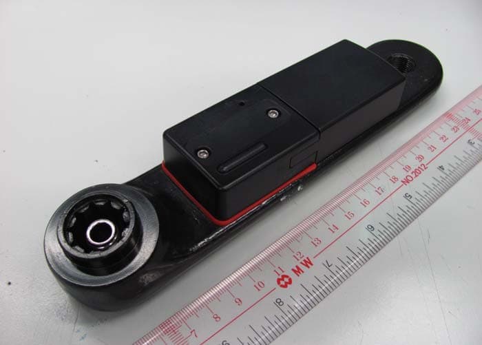
ZBMAD200B
Feb 29, 20122.4GHz Power Sensor
Equipment Class
DXX - Part 15 Low Power Communication Device Transmitter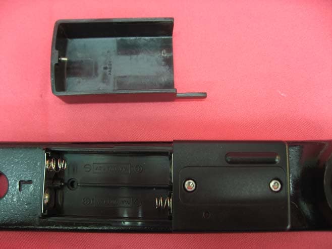
ZBMAD200
Jun 16, 2011Power Sensor
Equipment Class
DXX - Part 15 Low Power Communication Device Transmitter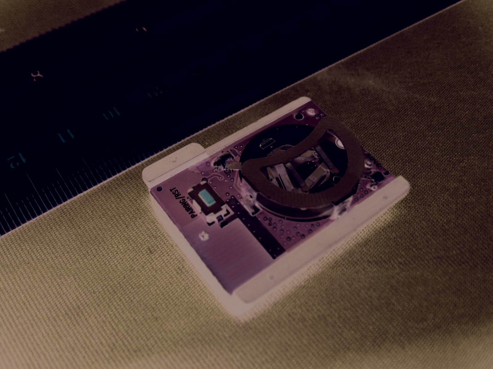
ZBMAD203
May 24, 2011RPM Sensor
Equipment Class
DXX - Part 15 Low Power Communication Device Transmitter