ZBMAD200Power Sensor
Foundation Fitness LLC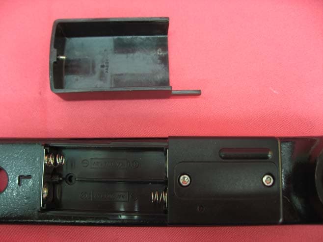
Click to zoom
Application Details
- Equipment Class
- DXX - Part 15 Low Power Communication Device Transmitter
- Date of Grant
- Jun 16, 2011
- Application Purpose
- Original Equipment
- Date of Application
- Jun 16, 2011
- Equipment Note
- Power Sensor
- Frequency Range
- 2457.00000000 - 2457.00000000
- Company
- Foundation Fitness LLC
- Country
- United States
Documents & Files
Document Text
Text extracted from the exhibit documents filed with the FCC. Open a document above to read the original.
Users Manual
USER’S MANUAL CAUTION Read all precautions and instruc- tions in this manual before using this equipment. Keep this manual for future reference. Model No. FMPW11.0/FMRPM11.0 QUESTIONS? If you have questions, or if parts are damaged or missing, please see HOW TO CONTACT CUSTOMER CARE on the back cover of this manual. www.freemotionfitness.com 2 TABLE OF CONTENTS FREEMOTION is a registered trademark of ICON IP, Inc. COMPLIANCE INFORMATION. . . . . . . . . . . . . . . . . . . . . . . . . . . . . . . . . . . . . . . . . . . . . . . . . . . . . . . . . . . . . . . . .2 IMPORTANT PRECAUTIONS . . . . . . . . . . . . . . . . . . . . . . . . . . . . . . . . . . . . . . . . . . . . . . . . . . . . . . . . . . . . . . . . . .3 CONSOLE FEATURES. . . . . . . . . . . . . . . . . . . . . . . . . . . . . . . . . . . . . . . . . . . . . . . . . . . . . . . . . . . . . . . . . . . . . . .4 SPECIFICATIONS. . . . . . . . . . . . . . . . . . . . . . . . . . . . . . . . . . . . . . . . . . . . . . . . . . . . . . . . . . . . . . . . . . . . . . . . . . .4 CONSOLE DIAGRAM . . . . . . . . . . . . . . . . . . . . . . . . . . . . . . . . . . . . . . . . . . . . . . . . . . . . . . . . . . . . . . . . . . . . . . . .5 POWER SENSOR DIAGRAM . . . . . . . . . . . . . . . . . . . . . . . . . . . . . . . . . . . . . . . . . . . . . . . . . . . . . . . . . . . . . . . . . .6 DISPLAY DIAGRAM . . . . . . . . . . . . . . . . . . . . . . . . . . . . . . . . . . . . . . . . . . . . . . . . . . . . . . . . . . . . . . . . . . . . . . . . .7 DISPLAY DEFINITIONS . . . . . . . . . . . . . . . . . . . . . . . . . . . . . . . . . . . . . . . . . . . . . . . . . . . . . . . . . . . . . . . . . . . . . .8 HOW TO USE THE CONSOLE. . . . . . . . . . . . . . . . . . . . . . . . . . . . . . . . . . . . . . . . . . . . . . . . . . . . . . . . . . . . . . . . 11 HOW TO LINK ANT+ COMPATIBLE DEVICES . . . . . . . . . . . . . . . . . . . . . . . . . . . . . . . . . . . . . . . . . . . . . . . . . . .18 HOW TO CONFIGURE THE CONSOLE. . . . . . . . . . . . . . . . . . . . . . . . . . . . . . . . . . . . . . . . . . . . . . . . . . . . . . . . .20 MAINTENANCE . . . . . . . . . . . . . . . . . . . . . . . . . . . . . . . . . . . . . . . . . . . . . . . . . . . . . . . . . . . . . . . . . . . . . . . . . . .28 TROUBLESHOOTING . . . . . . . . . . . . . . . . . . . . . . . . . . . . . . . . . . . . . . . . . . . . . . . . . . . . . . . . . . . . . . . . . . . . . .29 HOW TO CONTACT CUSTOMER CARE . . . . . . . . . . . . . . . . . . . . . . . . . . . . . . . . . . . . . . . . . . . . . . . . Back Cover COMPLIANCE INFORMATION This Class B digital apparatus complies with Canadian ICES-003. This device complies with Part 15 of the FCC Rules. Operation is subject to the following two conditions: (1) this device may not cause harmful interference, and (2) this device must accept any interference received, including interference that may cause undesired operation. Note: This equipment has been tested and found to comply with the limits for a Class B digital device, pursuant to Part 15 of the FCC Rules. These limits are designed to provide reasonable protection against harmful interference in a residential installation. This equipment generates, uses, and can radiate radio frequency energy and, if not installed and used in accordance with the instructions, may cause harmful interference to radio communications. However, there is no guarantee that interference will not occur in a particular installation. If this equipment does cause harmful interference to radio or television reception, which can be determined by turning the equipment off and on, try to correct the interference by one of the following measures: • Reorient or relocate the receiving antenna. • Increase the separation between the equipment and the receiver. • Consult the dealer or an experienced radio/TV technician for help. FCC/IC CAUTIONS: To assure continued compliance, use only shielded interface cables when connecting to computer or peripheral devices. Changes or modifications not expressly approved by the party respon- sible for compliance could void the user’s authority to operate this equipment. The console and the sensor are sensitive devices; the RF link between the console and the sensor may be dis- turbed by strong electromagnetic interference such as electro-static discharge. If this happens, please press the AVG/END button, and then press the STAGE button to relink the sensor. 3 WARNING: To reduce the risk of serious injury, read all important precautions and instructions in this manual and all warnings on your console before using your console. FreeMotion Fitness assumes no responsibility for personal injury or property damage sustained by or through the use of this product. 1. Before beginning any exercise program, consult your physician. This is especially important for persons over age 35 or per- sons with pre-existing health problems. 2. If you have an implanted medical device, such as a pacemaker, consult your physician before using a heart rate monitor. 3. If you are taking medication regularly, consult your physician to find out if the med- ication will affect your exercise heart rate. 4. Use the console only as described in this manual. 5. It is the responsibility of the owner to ensure that all users of the console are adequately informed of all precautions. 6. Keep the console indoors, away from mois- ture and dust. Do not put the console in a garage or covered patio, or near water. 7. Inspect and properly tighten all parts regu- larly. Replace any worn parts immediately. 8. Keep children under age 12 and pets away from the console at all times. 9. To avoid damage to the console, keep liquids away from the console and keep the console out of direct sunlight. 10. Clean the console with a soft, damp cloth only. Do not use abrasives or solvents to clean the console. 11. When storing the console and/or the sensor, remove the batteries. Store the console and/ or the senso…
Text truncated - open the document above for the full version.
Block Diagram
AD200 Block Diagram Crystal 12MHz Microcontroller Pre-Amp 2.4GHz Transmission IC nRF24AP2 Crystal 16MHz Antenna Matching Network Antenna Strain Gauge EEPROM Reed Switch Revision 1.0Page 14 of 59 nRF24AP2 Product Specification 3.2 Block diagram Figure 4. on page 14 shows a block diagram of the RF transceiver in nRF24AP2. Figure 4. Internal circuitry of RF transceiver relative to ANT RF Recei ver ANT1 ANT2 ANT protocol stack GFSK Modul at or PA LNA TX Fi l ter RX Fi l ter RF Synt hesi ser RF Transmitter GFSK Demodul at or
External Photos
INTERTEK TESTING SERVICE Report No.: HK11041104-1 FCC ID: ZBMAD200 Equipment Photographs Model: AD200 (External) INTERTEK TESTING SERVICE Report No.: HK11041104-1 FCC ID: ZBMAD200 Equipment Photographs Model: AD200 (External)
ID Label/Location Info
US or Canada: 1-800-201-2109 Other Regions: +1 435-786-3521 Made in China 42.8mm 14.8mm FCC ID: ZBMAD200 IC: 9327A-AD200 Model: AD200 Part: 310447 DC 3.0V 10mA US or Canada: 1-800-201-2109 Other Regions: +1 435-786-3521 Made in China FCC ZBMAD200 IC: 9327A-AD200 Model: AD200 Part: 310447 DC 3.0V 10mA 31mm 22mm US or Canada: 1-800-201-2109 Other Regions: +1 435-786-3521 Made in China FCC ID: ZBMAD203 IC: 9327A-AD203 Model: AD203 Part: 310446 DC 3.5V .02mA US or Canada: 1-800-201-2109 Other Regions: +1 435-786-3521 Made in China FCC ID: ZBMAD203 IC: 9327A-AD203 Model: AD203 Part: 310446 DC 3.0V .02mA US or Canada: 1-800-201-2109 Other Regions: +1 435-786-3521 Part:310445 Model: FB613 This Device Contains FCC ID: 06RFIT1 This Device Contains IC: 3797AFIT1 DC 4.5 40mA Made in China 56mm 22mm This device complies with Part 15 of the FCC Rules. Operation is subject to the following two conditions: (1) this device may not cause harmful interference, and (2) this device must accept any interference received, including interference that may cause undesired operation N136 N136 N136 N136 N136
Internal Photos
INTERTEK TESTING SERVICE Report No.: HK11041104-1 FCC ID: ZBMAD200 Equipment Photographs Model: AD200 (Internal) INTERTEK TESTING SERVICE Report No.: HK11041104-1 FCC ID: ZBMAD200 Equipment Photographs Model: AD200 (Internal)
Operational Description
AD200 Theory of Operation The AD200 power sensor is a sensor that detects the force that applies on the pedal of an exercise bike and calculate the power the user is using in his/her exercise. The AD200 worked with the FB613 console. There is a reed switch in the sensor. It is use to sense the angular speed of the pedal. The sensor also has a strain gauge to detect the force the user applies onto the pedal. The strain gauge signal is amplified by a pre-amp and feeds to the ADC input of the micro- controller. The MCU will calculate the power the user is exercising using the pedal angular speed and force applied on the pedal. The microcontroller in the power sensor activates the nRF24AP2 2.4GHz transceiver IC to send encoded 2.457 GHz RF signal containing the power and angular speed information to the FB613 console and the console displays the power and angular speed reading on its LCD and may store the received power and angular speed information in its internal memory. The RF output of the nRF24AP2 2.4GHz transmitter IC is connected to the antenna via an Antenna matching network. This network is used to match the impedance of the antenna to the nRF240AP2 2.4GHz transmitter IC and suppress unwanted spurious transmission. The power sensor needs calibration at the factory for correct operation. A static loading is put onto the power pedal. The console will transmit a calibration command to the power sensor via the 2.457MHz to activate the calibration process. When the power sensor receives the calibration command from the console it will read the force applied by the loading and store this information in its internal memory (EEPROM) to calculate the power. The data signal is transferred through matching network (L100, L101, L102, L103, L104, L105, L106, C111, C112, C113, C114, C105 and C106) fed to the antenna. All rights reserved. ANT TM is a trademark of Dynastream Innovation Inc. Reproduction in whole or in part is prohibited without the prior written permission of the copyright holder. September 2009 nRF24AP2 nRF24AP2-1CH, nRF24AP2-8CH Single-chip ANT TM ultra-low power wireless network solution Product Specification v1.0 Key Features •Second generation single chip ANT solution •nRF24AP2-1CH supports 1 ANT (logic) channel – ideal for sensors •nRF24AP2-8CH supports up to 8 ANT (logic) channels – ideal for hubs •World wide 2.4 GHz ISM band operation •Fully embedded, enhanced ANT protocol stack •True ultra-low power operation •Typically years of battery lifetime on a coin cell •Built-in device search and pairing •Built-in timing and power management •Built-in interference handling •Configurable channel period 5.2 ms - 2 seconds •Broadcast, Acknowledged and Burst communi- cation modes •Burst data rate up to 20 kbps •Simple to complex network topologies: Peer-to-peer, star, tree and practical mesh •Supports both public and private (managed) networks •Support for ANT+ device profile implementa- tions enabling multivendor interoperability •Fully interoperable with nRF24AP1 and Dynas- tream ANT chipset / module based products •Simple asynchronous/ synchronous host inter- face •Single 1.9 - 3.6V power supply •RoHS compliant 5x5 mm 32-pin QFN package •Low cost external 16 MHz crystal •Optional on-chip 32.768 kHz crystal oscillator Applications •Sport •Wellness •Home health monitoring •Home/industrial automation •Environmental sensor networks •Active RFID •Logistics/goods tracking •Audience-response systems Revision 1.0Page 2 of 59 nRF24AP2 Product Specification Liability disclaimer Nordic Semiconductor ASA reserves the right to make changes without further notice to the product to improve reliability, function or design. Nordic Semiconductor ASA does not assume any liability arising out of the application or use of any product or circuits described herein. All application information is advisory and does not form part of the specification. Limiting values Stress above one or more of the limiting values may cause permanent damage to the device. These are stress ratings only and operation of the device at these or at any other conditions above those given in the specifications are not implied. Exposure to limiting values for extended periods may affect device reliability. Life support applications These products are not designed for use in life support appliances, devices, or systems where malfunction of these products can reasonably be expected to result in personal injury. Nordic Semiconductor ASA cus- tomers using or selling these products for use in such applications do so at their own risk and agree to fully indemnify Nordic Semiconductor ASA for any damages resulting from such improper use or sale. Contact details For your nearest dealer, please see www.nordicsemi.no Main office: Otto Nielsens veg 12 7004 Trondheim Phone: +47 72 89 89 00 Fax: +47 72 89 89 89 www.nordicsemi.no Datasheet status Objective product specificationThis product specification contains target specifications for product development. Preliminary product specification This product specification contains preliminary data; supplementary data may be published from Nordic Semiconductor ASA later. Product specificationThis product specification contains final product specifications. Nordic Semiconductor ASA reserves the right to make changes at any time without notice in order to improve design and supply the best possible product. Revision 1.0Page 3 of 59 nRF24AP2 Product Specification RoHS statement nRF24AP2 where explicitly stated in this product specification meets the requirements of Directive 2002/ 95/EC of the European Parliament and of the Council on the Restriction of Hazardous Substances (RoHS). Complete hazardous substance reports as well as material composition reports for all active Nordic prod- ucts can be found on our web site www.nordicsemi.com . Revision History DateVersionDescription September 20091.0Product specification Revision 1.0Page 4 of 59 nRF24AP2 Product Specification Contents 1Introduction ..........…
Text truncated - open the document above for the full version.
Test Report
INTERTEK TESTING SERVICES Report No.: HK11041104-1 Sample No.: 1/1 Code: FCC15C_d / Effective Date: 26 Jan 2010 ( of ) Average Factor Plot - Pursuant to FCC Part 15 Section 15.249 Requirement (Pass/Fail) INTERTEK TESTING SERVICES Report No.: HK11041104-1 Sample No.: 1/1 Code: FCC15C_d / Effective Date: 26 Jan 2010 ( of ) Average Factor Plot - Pursuant to FCC Part 15 Section 15.249 Requirement (Pass/Fail) INTERTEK TESTING SERVICES Report No.: HK11041104-1 Sample No.: 1/1 Code: FCC15C_d / Effective Date: 26 Jan 2010 ( of ) Average Factor Plot - Pursuant to FCC Part 15 Section 15.249 Requirement (Pass/Fail)
Test Report
INTERTEK TESTING SERVICES Report No.: HK11041104-1 Sample No.: 1/1 Code: FCC15C_d / Effective Date: 26 Jan 2010 ( of ) Bandedge Plot - Pursuant to FCC Part 15 Section 15.249 Requirement (Pass/Fail) OATS = 96.00 dBuV/m Field Strength (Peak) =96.00 – 41.48 dBuV/m =54.52 dBuV/m Field Strength (Average) =54.52 – AF dBuV/m =54.52 – 54.20 dBuV/m =0.32 dBuV/m OATS = 96.00 dBuV/m Field Strength (Peak) =96.00 – 40.40 dBuV/m =55.60 dBuV/m Field Strength (Average) =55.60 – AF dBuV/m =55.60 – 54.20 dBuV/m =1.40 dBuV/m
Test Report
- The test report only allows to be revised within the retention period unless further standard or the requirement was noticed. - This report is for the exclusive use of Intertek's Client and is provided pursuant to the agreement between Intertek and its Client. Intertek's responsibility and liability are limited to the terms and conditions of the agreement. Intertek assumes no liability to any party, other than to the Client in accordance with the agreement, for any loss, expense or damage occasioned by the use of this report. Only the Client is authorized to permit copying or distribution of this report and then only in its entirety. Any use of the Intertek name or one of its marks for the sale or advertisement of the tested material, product or service must first be approved in writing by Intertek. The observations and test results in this report are relevant only to the sample tested. This report by itself does not imply that the material, product, or service is or has ever been under an Intertek certification program. Intertek Testing Services Hong Kong Ltd. 2/F., Garment Centre, 576 Castle Peak Road, Kowloon, Hong Kong. Tel: (852) 2173 8888 Fax: (852) 2785 5487 Website: www.hk.intertek-etlsemko.com TEST REPORT Report No.: HK11041104-1 Foundation Fitness LLC Application For Certification (Original Grant) (FCC ID: ZBMAD200) Transceiver Prepared and Checked by: Approved by: Signed On File Kung Wing Cheong, Steven Assistant Engineer Chan Chi Hung, Terry Assistant Supervisor Date: June 15, 2011 INTERTEK TESTING SERVICES Report No.: HK11041104-1 FCC ID: ZBMAD200 i GENERAL INFORMATION Foundation Fitness LLC BRAND NAME: Freemotion, MODEL: AD200 FCC ID: ZBMAD200 Grantee: Foundation Fitness LLC Grantee Address: 1732 NW Quimby Street, Ste 250, Portland, OR 97209, USA. Contact Person: Douglas Crawford Tel: (855) 505-9538 Fax: (877) 867-3721 e-mail: [email protected] Manufacturer: IDT Communication Technology Limited Manufacturer Address: Chentian Industrial Estate, XiXian, Bao An, Shenzhen, PRC. China Brand Name: Freemotion Model: AD200 Type of EUT: Transceiver Description of EUT: Power Sensor Serial Number: N/A FCC ID: ZBMAD200 Date of Sample Submitted: April 20, 2011 Date of Test: May 11, 2011 Report No.: HK11041104-1 Report Date: June 15, 2011 Environmental Conditions: Temperature: +10 to 40°C Humidity: 10 to 90% INTERTEK TESTING SERVICES Report No.: HK11041104-1 FCC ID: ZBMAD200 ii SUMMARY OF TEST RESULT Foundation Fitness LLC BRAND NAME: Freemotion, MODEL: AD200 FCC ID: ZBMAD200 TEST SPECIFICATION REFERENCE RESULTS Maximum Peak Output Power 15.247(b), (c) / RSS-210 A8.4 N/A Hopping Channel Carrier Frequencies Separation 15.247(e) / RSS-210 A8.1 N/A 20dB Bandwidth of the Hopping Channel 15.247(a) / RSS-210 A8.1 N/A Number of Hopping Frequencies 15.247(e) / RSS-210 A8.1 N/A Average Time of Occupancy of Hopping Frequency 15.247(e) / RSS-210 A8.1 N/A Antenna Conducted Spurious Emissions 15.247(d) / RSS-210 A8.5 N/A Radiated Spurious Emissions 15.247(d) / RSS-210 A8.5 N/A RF Exposure Compliance 15.247(i) / RSS-Gen 5.5 N/A Transmitter Power Line Conducted Emissions 15.207 / RSS-Gen 7.2.2 N/A Transmitter Field Strength 15.227 / RSS-310 3.8 N/A Transmitter Field Strength 15.229 / RSS-210 A2.7 N/A Transmitter Field Strength, Bandwidth and Timing Requirement 15.231(a) / RSS-210 A1.1.1 N/A Transmitter Field Strength, Bandwidth and Timing Requirement 15.231(e) / RSS-210 A1.1.5 N/A Transmitter Field Strength and Bandwidth Requirement 15.239 / RSS-210 A2.8 N/A Transmitter Field Strength and Bandwidth Requirement 15.249 / RSS-210 A2.9 Pass Transmitter Field Strength and Bandwidth Requirement 15.235 / RSS-310 3.9 N/A Receiver / Digital Device Radiated Emissions 15.109 / ICES-003 N/A Digital Device Conducted Emissions 15.107 / ICES-003 N/A Note: 1. The EUT uses a permanently attached antenna which, in accordance to section 15.203, is considered sufficient to comply with the pervisions of this section. 2. Pursuant to FCC part 15 Section 15.215(c), the 20 dB bandwidth of the emission was contained within the frequency band designated (mentioned as above) which the EUT operated. The effects, if any, from frequency sweeping, frequency hopping, other modulation techniques and frequency stability over excepted variations in temperature and supply voltage were considered. INTERTEK TESTING SERVICES Report No.: HK11041104-1 FCC ID: ZBMAD200 iii Table of Contents 1.0 General Description....................................................................................... 1 1.1 Product Description ...................................................................................... 1 1.2 Related Submittal(s) Grants .......................................................................... 1 1.3 Test Methodology ......................................................................................... 1 1.4 Test Facility .................................................................................................. 1 2.0 System Test Configuration ............................................................................ 2 2.1 Justification................................................................................................... 2 2.2 EUT Exercising Software .............................................................................. 2 2.3 Special Accessories...................................................................................... 2 2.4 Equipment Modification................................................................................. 2 2.5 Measurement Uncertainty ............................................................................. 2 2.6 Support Equipment List and Description........................................................ 2 3.0 Emission Results ........................................................................................... 3 3.1 Field Strength Calculation ............................................................................. 3 3.2 Radiated…
Text truncated - open the document above for the full version.
Test Setup Photos
INTERTEK TESTING SERVICE Report No: HK11041104-1 FCC ID: ZBMAD200 Configuration Photographs Worst-Case Radiated Emissions (Front View) Model: AD200 INTERTEK TESTING SERVICE Report No: HK11041104-1 FCC ID: ZBMAD200 Configuration Photographs Worst-Case Radiated Emissions (Back View) Model: AD200
Contact Information
Applicant
Douglas Crawford(Senior VP)
Technical Contact
Intertek Testing Services Hong Kong LtdTerry Chan
[email protected]2173 8503
2/F Garment Centre · Kowloon · Hong Kong
Non-Technical Contact
Intertek Testing Services Hong Kong LtdTerry Chan
[email protected]2173 8503
Test Firm
Intertek Testing Services Hong Kong Ltd.Billy Chow
Technical Specifications
| # | Rule Parts | Frequency Range | Power Output |
|---|---|---|---|
| 1 | 15C | 2.46 GHz - 2.46 GHz | - |
Other Applications from Foundation Fitness LLC

ZBM-SBSB1
May 20, 2020Stages Bike
Equipment Class
DTS - Digital Transmission System
ZBM-SIP1
Apr 15, 2015Stages indoor Power Meter
Equipment Class
DTS - Digital Transmission System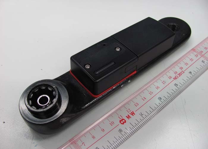
ZBMAD200B
Feb 29, 20122.4GHz Power Sensor
Equipment Class
DXX - Part 15 Low Power Communication Device Transmitter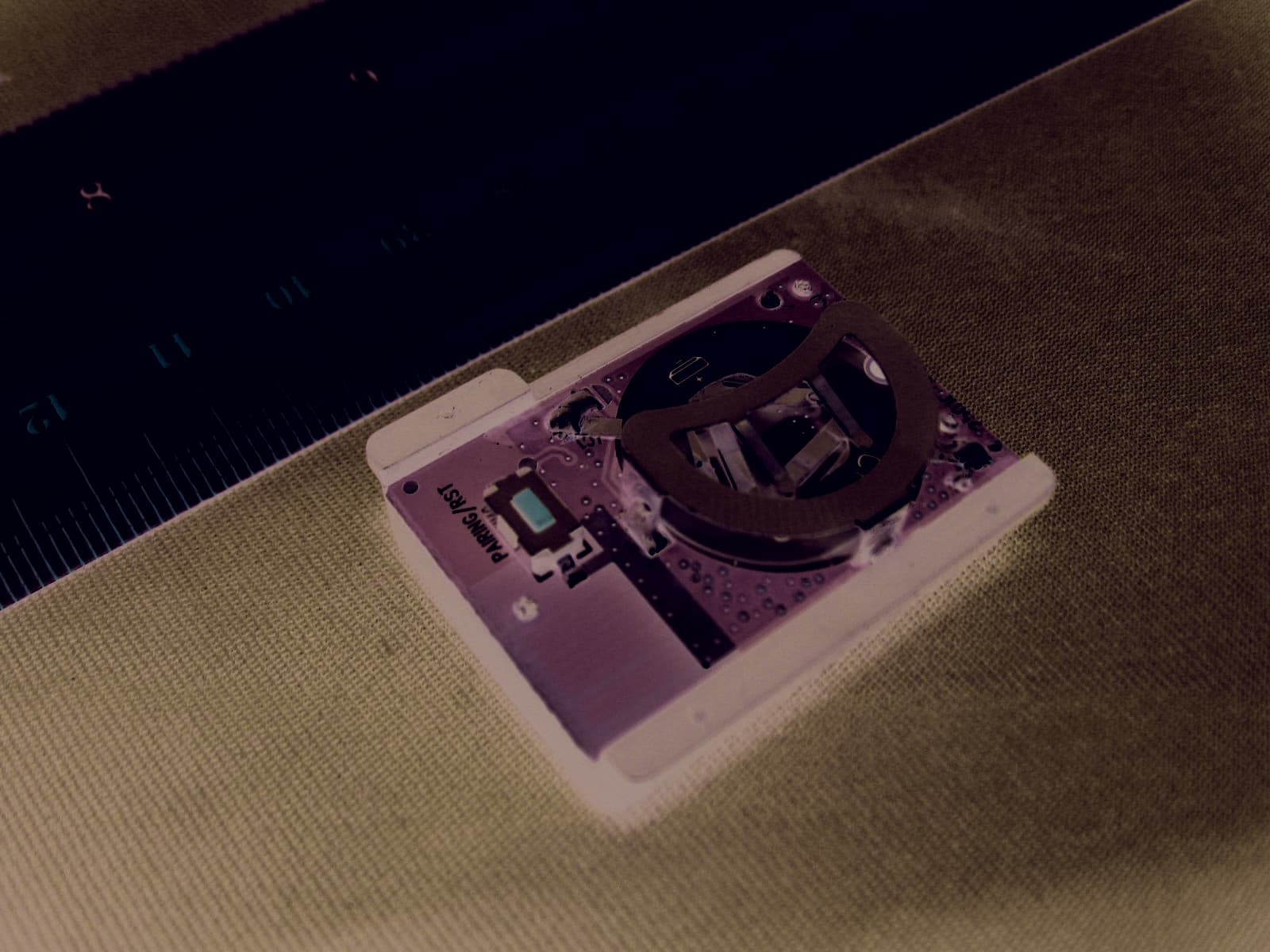
ZBMAD203
May 24, 2011RPM Sensor
Equipment Class
DXX - Part 15 Low Power Communication Device Transmitter