ZC8S321NETWORKGNSS Survey Receiver
Hemisphere GNSS Inc.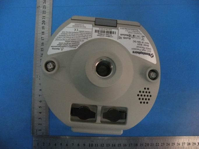
Click to zoom
Application Details
- Equipment Class
- DTS - Digital Transmission System
- Date of Grant
- Jan 25, 2016
- Application Purpose
- Original Equipment
- Date of Application
- Jan 25, 2016
- Equipment Note
- GNSS Survey Receiver
- Frequency Range
- 2412.00000000 - 2462.00000000
- Company
- Hemisphere GNSS Inc.
- Country
- United States
Documents & Files
Document Text
Text extracted from the exhibit documents filed with the FCC. Open a document above to read the original.
Users Manual
GNSS Survey Receiver User's Guide Part No. 875-0357-D Rev. A1 Environmental Temperature – operating -20°C to +40°C Temperature – storage -40°C to +60°C Humidity MIL-STD-810F Method 5-7.4 Vibration MIL-STD-810FG Method. 514.6E-1 Loose cargo MIL-STD-810F FIG. 514.5C-5 Regulatory Compliance CE Compliance •I EC 60950-1: 2005 •EN 301 113-1 / EN 301 113-2 •EN 301 489-1 v1.9.2 •EN301 489-3 v1.6.1 •EN301 489-7 v1.3.1 •EN 301489-17 v2.2.1 •EN301 489-24 v1.5.1 •EN55022:2010 •EN55024:2010 •EN 300440-1 v1.6.1 / EN 300440-2 v1.4.1 •EN 300 328 V1.9.1 •EN 301 511 v9.0.2 •EN 301 908-1 v6.2.1 / EN 301 908-2 v6.2.1 • FCC Compliance •FCC Part 15, Subpart B •FCC Part 15, Subpart C :2015 •FCC Part 15, Subpart C :2014 •FCC Part 2 •FCC Part 22H •FCC Part 24E IC Compliance •ICES-003:2012 Issue 5 •RSS-247 Issue 1 •RSS-GEN Issue 4 •RSS 132 Issue 3 •RSS 133 Issue 6 Certifications S321 UHF •Model: S321 UHF •FCC ID: ZC8S321UHF •IC: 9586A-S321UHF S321 Non-UHF •Model: S321 Network •FCC ID: ZC8S321Network •IC: 9586A-S321Network If your S321 is equipped with a UHF radio you may be required to obtain a valid radio license for your jurisdiction. Only set the radio to the frequency and power you are licensed to use at your location. USA- Federal Communication Commission (FCC) Radio frequency radiation exposure Information: This equipment complies with FCC radiation exposure limits set forth for an uncontrolled environment. This equipment should be installed and operated with a minimum distance of 20 cm between the radiator and your body. This transmitter must not be co-located or operating in conjunction with any other antenna or transmitter. Modifications not expressly approved by Hemisphere GNSS could void the user's authority to operate the equipment. This device complies with Part 15 of the FCC Rules. Operation is subject to the following two conditions: (1) this device may not cause harmful interference, and (2) this device must accept any interference received, including interference that may cause undesired operation. This equipment has been tested and found to comply with the limits for a Class B digital device, pursuant to Part 15 of FCC Rules. These limits are designed to provide reasonable protection against harmful interference in a residential installation. This equipment generates, uses, and can radiate radio frequency energy. If not installed and used in accordance with the instructions, it may cause harmful interference to radio communications. However, there is no guarantee that interference will not occur in a particular installation. If this equipment does cause harmful interference to radio or television reception, which can be determined by tuning the equipment off and on, the user is encouraged to try and correct the interference by one or more of the following measures: •Reorient or relocate the receiving antenna. •Increase the distance between the equipment and the receiver. •Connect the equipment to an outlet on a circuit different from that to which the receiver is connected. •Consult the dealer or an experienced radio/TV technician for help. Any changes or modifications not expressly approved by the party responsible for compliance could void the user's authority to operate the equipment. Canada - Industry Canada (IC) This device complies with RSS 210 of Industry Canada. Operation is subject to the following two conditions: (1) this device may not cause interference, and (2) this device must accept any interference, including interference that may cause undesired operation of this device. L ' utilisation de ce dispositif est autorisée seulement aux conditions suivantes: (1) il ne doit pas produire d'interference et (2) l' utilisateur du dispositif doit étre prêt à accepter toute interference radioélectrique reçu, même si celle-ci est susceptible de compromettre le fonctionnement du dispositif. Caution: Exposure to Radio Frequency Radiation. This equipment should be installed and operated with a minimum distance of 20 cm between the radiator and your body. Europe – Declaration of Conformity This device is in compliance with the essential requirements of the R&TTE Directive 1999/5/EC. Copyright Notice Hemisphere GNSS Copyright © Hemisphere GNSS (2015). All rights reserved. No part of this manual may be reproduced, transmitted, transcribed, stored in a retrieval system or translated into any language or computer language, in any form or by any means, electronic, mechanical, magnetic, optical, chemical, manual or otherwise, without the prior written permission of Hemisphere GNSS. Trademarks Hemisphere GNSS ® , the Hemisphere GNSS logo, A100 TM , A20 TM , A21 TM , A30 TM , A31 TM , A42 TM , A52 TM , COAST TM , Crescent ® , Eclipse TM , e-Dif ® , H102 TM , H320 TM , L-Dif TM , LV101 TM , LX-1 TM , LX-2 TM , PocketMax PC TM , PocketMax TM , PocketMax3 TM , R100 TM , R131 TM , R220 TM , R320 TM , S321 TM , SBX-4 TM , SLXMon TM , SureTrack ® , V101 TM , V102 TM , V103 TM , V111 TM , V113 TM , VS101 TM , VS111 TM , Vector TM are proprietary trademarks of Hemisphere GNSS. Other trademarks are the properties of their respective owners. Patents Hemisphere GNSS products may be covered by one or more of the following U.S. Patents: Other U.S. and foreign patents pending. Notice to Customers Contact your local dealer for technical assistance. To find the authorized dealer near you: Hemisphere GNSS 8515 East Anderson Drive Scottsdale, Arizona 85255 Phone: 480-348-6380 Fax: 480-270-6070 [email protected] www.hgnss.com Technical Support If you need to contact Hemisphere GNSS Technical Support: 8515 East Anderson Drive Scottsdale, Arizona 85255 Phone: 480-348-6380 Fax: 480-270-6070 [email protected] Documentation Feedback Hemisphere GNSS is committed to the quality and continuous improvement of our products and services. We urge you to provide Hemisphere GNSS with any feedback regarding this guide by writing to the following email address: [email protected]. 6,111,5496,397,1476,469,6636,501,3466,539…
Text truncated - open the document above for the full version.
Cover Letter(s)
2015-12-02 Equipment Autorisation Division Federal Communications Commission 7435 Oakland Mills Road Columbia, MD 21046 FCC ID: ZC8S321NETWORK Product Name: GNSS Survey Receiver Request for Confidentiality Pursuant to Sections 0.457 and 0.459 of the commissions rules, we hereby request that the following documents be held confidential: Schematics Long-term confidential Block diagram Long-term confidential Operation description Long-term confidential Tune-up procedure Long-term confidential These materials contain trade secrets and proprietary information and are not customarily released to the public. The public disclosure of this information might be harmful to the company and provide unjustified benefits to our competitors. Signature: 2015-12-02 Name Brad Badke Position Vice President, Product Developement Company Name Hemisphere GNSS Inc. Address 8444 N 90th Street, Suite 120, Scottsdale, Arizona, United States, 85258 Tel 1 480 348 6393 Fax 1 480 270 5070 Email [email protected]
ID Label/Location Info
Label Location
RF Exposure Info
Prediction of MPE limit at a given distance Equation from page 18 of OET Bulletin 65, Edition 97-01 where:S = power density P = power input to the antenna G = power gain of the antenna in the direction of interest relative to isotropic R = distance to the center of radiation of the antenna Maximum peak output power at antenna input terminal:17.35(dBm) Maximum peak output power at antenna input terminal:54.3(mW) Antenna gain(typical):3.92(dBi) Maximum antenna gain:2.466(numeric) Prediction distance:20(cm) Sourse Based Time Average Duty Cycle:100(%) Prediction frequency:2412(MHz) MPE limit for uncontrolled exposure at prediction frequency:1.000(mW/cm^2) Power density at prediction frequency:0.02665(mW/cm^2) Power density at prediction frequency:0.2665(W/m^2) Margin of Compliance:15.74(dB) 2 4R PG S p =
Test Report
Page 1 of 63 Report No.: T1851403 16 TEST REPORT FCC ID: ZC8S321NETWORK Applicant : Hemisphere GNSS Inc. Address : 8515 E Anderson Dr, Scottsdale, AZ 85255, USA Equipment under Test (EUT): Name : GNSS Survey Receiver Model : S321 Network , BRx6 Network In Accordance with: FCC PART 15, SUBPART C: 2015 (Section 15.247) ANSI C63.10:2013 Report No : T1851403 16 Date of Test : September 22- November 16, 2015 Date of Issue : November 16, 2015 Test Result : PASS Test Result: PASS In the configuration tested, the EUT complied with the standards specified above Authorized Signature ___________________________ (Mark Zhu) General Manager The manufacture should ensure that all the products in series production are in conformity with the product sample detailed in this report. If the product in this report is used in any configuration other than that detailed in the report, the manufacturer must ensure the new system complies with all relevant standards. Any mention of Shenzhen Alpha Product Testing Co., Ltd. Or test done by Shenzhen Alpha Product Testing Co., Ltd. Approvals in connection with, distribution or use of the product described in this report must be approved by Shenzhen Alpha Product Testing Co., Ltd. Approvals in writing. Page 2 of 63 Report No.: T1851403 16 TABLE OF CONTENT Description Page 1 General Information --------------------------------------------------------------------------------------- 5 1.1 Description of Device (EUT) --------------------------------------------------------------------- 5 1.2 Description of Test Facility ----------------------------------------------------------------------- 6 2 EMC Equipment List ------------------------------------------------------------------------------------ 6 3 Test Procedure ------------------------------------------------------------------------------------------- 7 4 Summary of Measurement ---------------------------------------------------------------------------- 8 4.1 Summary of test result ---------------------------------------------------------------------------- 8 4.2 Test connection ------------------------------------------------------------------------------------- 8 4.3 Assistant equipment used for test ---------------------------------------------------------------- 8 4.4 Test mode ------------------------------------------------------------------------------------------- 9 4.5 Channel list ----------------------------------------------------------------------------------------- 9 4.6 Test Conditions ------------------------------------------------------------------------------------- 9 4.7 Measurement Uncertainty (95% confidence levels, k=2)----------------------------------- 10 5 Spurious Emission ---------------------------------------------------------------------------------- 11 5.1 Radiation Emission ------------------------------------------------------------------------------ 11 5.1.1 Radiation Emission Limits(15.209) ----------------------------------------------------------- 11 5.1.2 Test Setup ----------------------------------------------------------------------------------------- 11 5.1.3 Test Procedure ------------------------------------------------------------------------------------ 13 5.1.4 Test Equipment Setting For emission test Result -------------------------------------------- 13 5.1.5 Test Condition ------------------------------------------------------------------------------------ 14 5.1.6 Test Result ---------------------------------------------------------------------------------------- 14 6 POWER LINE CONDUCTED EMISSION ------------------------------------------------------- 29 6.1 Conducted Emission Limits(15.207) ---------------------------------------------------------- 29 6.2 Test Setup ----------------------------------------------------------------------------------------- 29 6.3 Test Procedure ------------------------------------------------------------------------------------ 30 6.4 Test Results --------------------------------------------------------------------------------------- 30 7 Conducted Maximum Output Power ----------------------------------------------------------- 31 7.1 Test limit ------------------------------------------------------------------------------------------ 31 7.2 Test Procedure ------------------------------------------------------------------------------------ 31 7.3 Test Setup ----------------------------------------------------------------------------------------- 31 7.4 Test Results --------------------------------------------------------------------------------------- 31 8 PEAK POWER SPECTRAL DENSITY ---------------------------------------------------------- 33 8.1 Test limit ------------------------------------------------------------------------------------------ 33 8.2 Method of measurement ------------------------------------------------------------------------ 33 8.3 Test Setup ----------------------------------------------------------------------------------------- 33 8.4 Test Results --------------------------------------------------------------------------------------- 34 9 Bandwidth ---------------------------------------------------------------------------------------------- 41 9.1 Test limit ------------------------------------------------------------------------------------------ 41 9.2 Method of measurement ------------------------------------------------------------------------ 41 9.3 Test Setup ----------------------------------------------------------------------------------------- 41 9.4 Test Results --------------------------------------------------------------------------------------- 41 10 Band Edge Check ------------------------------------------------------------------------------------ 49 10.1 Test limit ------------------------------------------------------------------------------------------ 49 10.2 Test Procedure ------------------------------------------------------------------------------------ 49 10.3 Test Setup ---------…
Text truncated - open the document above for the full version.
Contact Information
Applicant
Brad P Badke(Vice President, Product Developement)
Test Firm
Shenzhen Alpha Product Testing Co., Ltd.Mark Zhu
Technical Specifications
| # | Rule Parts | Frequency Range | Power Output |
|---|---|---|---|
| 1 | 15C | 2.41 GHz - 2.46 GHz | 54.30 mW |
Other Applications from Hemisphere GNSS Inc.
ZC8IRONTWO
Apr 20, 2021Panel PC
Equipment Class
PCB - PCS Licensed Transmitter