ZCAEBU2510Wireless Package Battery
SAMSUNG Electronics Co., Ltd.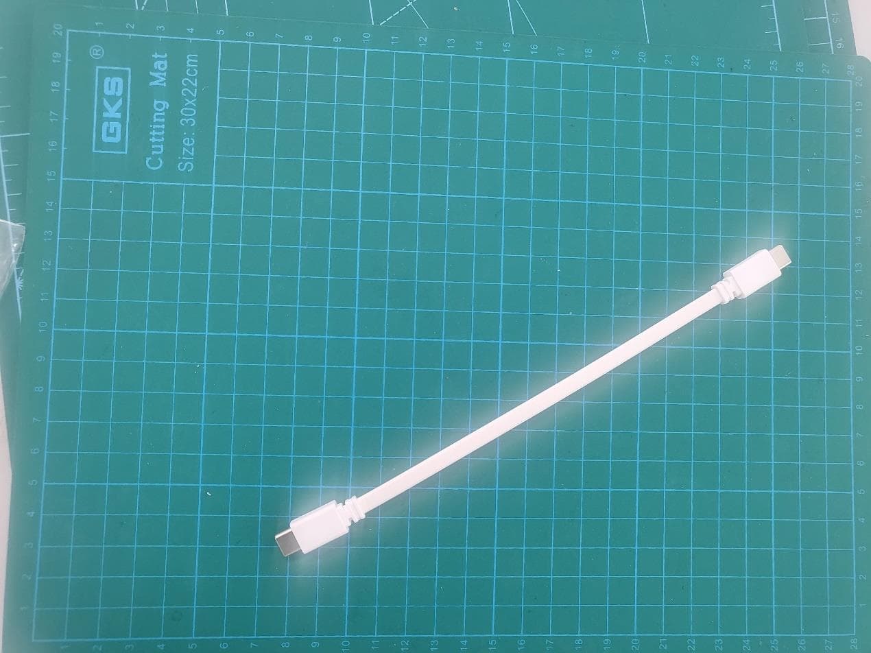
Click to zoom
Application Details
- Equipment Class
- DCD - Part 15 Low Power Transmitter Below 1705 kHz
- Date of Grant
- Nov 20, 2023
- Application Purpose
- Original Equipment
- Date of Application
- Nov 02, 2023
- Equipment Note
- Wireless Package Battery
- Frequency Range
- 0.11200000 - 0.14500000
- Country
- United States
Documents & Files
Document Text
Text extracted from the exhibit documents filed with the FCC. Open a document above to read the original.
Users Manual
www.samsung.com USER MANUAL 02/2020. Rev.1.0 EB-U2510 WIRELESS BATTERY PACK Table of Contents Eng lish (UK) 3 Read me first Please read this manual before using the device to ensure safe and proper use. • Images may differ in appearance from the actual product. Content is subject to change without prior notice. • Before using the wireless battery pack, make sure it is compatible with your device. Instructional icons Warning: situations that could cause injury to yourself or others Caution: situations that could cause damage to your device or other equipment Notice: notes, usage tips, or additional information English (UK) 1 4 Getting started Package contents Check the product box for the following items: • Wireless battery pack • USB cable • Quick start guide • Wireless charging covers are sold separately. • The items supplied with the device and any available accessories may vary depending on the region or service provider. • The supplied items are designed only for this device and may not be compatible with other devices. • Appearances and specifications are subject to change without prior notice. • You can purchase additional accessories from your local Samsung retailer. Make sure they are compatible with the device before purchase. • Use only Samsung-approved accessories. Using unapproved accessories may cause the performance problems and malfunctions that are not covered by the warranty. • Availability of all accessories is subject to change depending entirely on manufacturing companies. For more information about available accessories, refer to the Samsung website. English (UK) 2 Getting started 5 Device layout Charging the battery Battery charging tips and precautions • You can charge the wireless battery pack using the charger (sold separately). • Using a power source other than the charger, such as a computer, may result in a slower charging speed due to a lower electric current. • The wireless battery pack can be used while it is charging, but it may take longer to fully charge the battery. • While charging, the wireless battery pack may heat up. This is normal and should not affect the wireless battery pack’s lifespan or performance. If the battery gets hotter than usual, the charger may stop charging. • The actual capacity (Wh) is measured based on the battery’s output current and voltage. It may differ from the capacity (Wh) indicated on the device, depending on the output power condition, the connected device’s circuit configuration, and the operation environment. • If the wireless battery pack is not charging properly, take the wireless battery pack and the charger to a Samsung Service Centre. English (UK) 3 Getting started 6 Charging Charge the battery before using the wireless battery pack for the first time or when the wireless battery pack has been unused for extended periods. 1 Connect the wireless battery pack to a charger. When the charger is correctly connected to the wireless battery pack, the indicator light will turn on and flash. 2 When the wireless battery pack is fully charged, disconnect the wireless battery pack from the charger. English (UK) 4 Getting started 7 Checking the remaining battery power The indicator light informs you of the remaining battery power. Check the remaining battery power by pressing the wireless battery pack’s button. Remaining battery powerIndicator light 70~100 % • Four indicator lights on 40~70 % • Three indicator lights on 20~40 % • Two indicator lights on 5~20 % • One indicator light on 0~5 % • One indicator light blinking • If the indicator light does not work as described, disconnect the charger from the wireless battery pack and reconnect it. • The indicator light may work differently depending on the mobile device, watch, or the wireless charging cover. English (UK) 5 8 Using the wireless battery pack Charging devices Charging with a cable 1 Connect one end of the USB cable to the wireless battery pack’s USB charger port. Then, plug the other end of the USB cable into the mobile device’s multipurpose jack. 2 When the mobile device is fully charged, remove the mobile device from the battery pack. English (UK) 6 Using the wireless battery pack 9 Charging wirelessly 1 Place a supported mobile device or watch on the wireless charging surface. • The wireless charging indicator light will turn on, and charging will begin when the charging coil comes into contact with the wireless charging coil of the mobile device or watch. • Check the charging icon displayed on the mobile device or watch’s screen for the charging status. • If the charger is not connected, you must press the wireless battery pack’s button to charge the mobile device or watch wirelessly. 2 When the mobile device or watch is fully charged, remove the mobile device or watch from the wireless charger. Precautions for mobile device or watch charging • Do not place the mobile device on the wireless battery pack with a credit card or radio-frequency identification (RFID) card (such as a transportation card or a key card) placed between the back of the mobile device and the mobile device cover. • Do not place the mobile device or watch on the wireless battery pack when conductive materials, such as metal objects and magnets, are placed between the mobile device or watch and the wireless battery pack. The mobile device or watch may not charge properly or may overheat, or the mobile device, watch, or the cards may be damaged. English (UK) 7 Using the wireless battery pack 10 • You may need to purchase a charger separately depending on the wireless battery pack you bought. • Charging time may vary depending on the charging conditions. • Depending on the location of the mobile device or watch’s wireless charging coil, your mobile device or watch may not charge properly. • To begin fast charging, connect a mobile device or watch that supports fast charging to the wireless battery pack. • You can charge via a cable and wirelessly while the charger is connected to the wireless b…
Text truncated - open the document above for the full version.
Attestation Statements
47 CFR §2.911 (d)(7) Agent Designation Attestation Date: 02-08-2023 FCC ID: ZCAEBU2510 To: Federal Communications Commission 7435 Oakland Mills Road Columbia, MD 21046 USA Samsung Electronics Co., Ltd. (“the applicant”) as required by section 2.911(d)(7), designates the following agent, located in the United States, for purposes of acting as the applicant’s agent for service of process. The applicant acknowledges that they will maintain an agent for no less than one year after the grantee has terminated all marketing and importation or the conclusion of any Commission-related proceeding involving the equipment. The applicant further acknowledges their responsibility to inform the FCC whenever the agent information changes. U. S. Agent Information: Contact Person : Ms. Jenni Chun Company Name : Samsung Electronics America, Inc. Company Address : 19 Chapin Rd., Building D, Pine Brook, NJ 07058 Email : [email protected] Grantee Code: ZCA FRN #: 0027908797 Telephone No: 1-973-808-6375 Sincerely yours, Name: Ms. Jenni Chun Job Title: Head of Regulatory & Environmental Affairs Company Name: Samsung Electronics Co., Ltd.
Attestation Statements
47 CFR §2.903 and §2.911 (d)(5) Attestation Date: 02-08-2023 FCC ID: ZCAEBU2510 To: Federal Communications Commission 7435 Oakland Mills Road Columbia, MD 21046 USA 1. Samsung Electronics Co., Ltd. (“the applicant”) certifies that the equipment for which authorization is sought is not “covered” equipment prohibited from receiving an equipment authorization pursuant to section 2.903 of the FCC rules. 2. Samsung Electronics Co., Ltd. (“the applicant”) certifies that, as of the date of the filing of the application, the applicant is not identified on the Covered List as an entity producing “covered” equipment and is not an affiliate or subsidiary of an entity identified on the Covered List. Sincerely yours, Name: Ms. Jenni Chun Job Title: Head of Regulatory & Environmental Affairs Company Name: Samsung Electronics Co., Ltd.
Cover Letter(s)
Samsung Electronics Co., Ltd. 19 Chapin Rd.,Building D Pine Brook, NJ 07058 Tel: +1-201-937-4203 Authority to Act as Agent Date: __0802,2023_____ American Certification Body, Inc. 6731 Whittier Avenue Suite C110 McLean, VA 22101 To Whom It May Concern: ______(CTTL,Telecommunica tion Technology Labs,CAICT)_ _____ is authorized to act on our behalf, until otherwise notified, for applications to American Certification Body, Inc. (ACB). We certify that we are not subject to denial of federal benefits, that includes FCC benefits, pursuant to Section 5301 of the Anti-Drug Abuse Act of 1988, 21 U.S.C. 862. Further, no party, as defined in 47 CFR 1.2002 (b) , to the application is subject t o denial of federal benefits, that includes FCC benefits. Thank you, Agency Agreement Expiration Date: _____12 months_____ By: ____________ _____Jenni Chun_________ (Signature 1 ) (Print name) Title: ______General Manag er ________ On behalf of: __Samsung Electronics Co., Ltd. ___ (Company Name) Telephone: ___973-808-6375____ 022818 – 11 1 - Must be signed by applicant contact given for applicant on the FCC site, or by the authorized agent if an appropriate authorized agent letter has been provided. Letters should be placed on appropriate letterhead. Samsung Electronics Co., Ltd. 19 Chapin Rd.,Building D Pine Brook, NJ 07058 Tel: +1-201-937-4203 Request for Confidentiality Date: _0828,2023__ Subject: Confidentiality Request for: ____ZCAEBU2510____ Pursuant to FCC 47 CFR 0.457(d) and 0.459 and IC RSP-100, Section 9.4, the applicant requests that a part of the subject FCC application be held confidential. Type of Confidentiality Requested ☐Short Term☒Permanent ☒Short Term ☒Short Term☐Permanent * 2 ☐Short Term ☐Short Term ☐Short Term ☒Permanent ☒Permanent ☒Permanent ☒Short Term ☒Short Term ☐Permanent * 3 Exhibit Block Diagrams External Photos Internal Photos Operation Description/Theory of Operation Parts List & Placement/BOM Schematics Test Setup Photos User’s Manual _____SAMSUNG Electronics______ has spent substantial effort in developing this product and it is one of the first of its kind in industry. Having the subject information easily available to "competition" would negate the advantage they have achieved by developing this product. Not protecting the details of the design will result in financial hardship. Permanent Confidentiality: The applicant requests the exhibits listed above as permanently confidential be permanently withheld from public review due to materials that contain trade secrets and proprietary information not customarily released to the public. Short-Term Confidentiality: The applicant requests the exhibits selected above as short term confidential be withheld from public view for a period of __180___ days from the date of the Grant of Equipment Authorization and prior to marketing. This is to avoid premature release of sensitive information prior to marketing or release of the product to the public. Applicant is also aware that they are responsible to notify ACB in the event information regarding the product or the product is made available to the public before the requested period has expired. ACB will then release the The asterisked items (*) require further information to be provided to ACB before permanent confidentiality will be extended to these exhibits. Please refer to FCC KDB 726920 and the specific Document link for D01 found at: https://apps.fcc.gov/oetcf/kdb/forms/FTSSearchResultPage.cfm?switch=P&id=41731 and review section II, 3) regarding specific information that must accompany these requests. documents listed above for public disclosure pursuant to FCC Public Notice DA 04-1705. NOTE for Industry Canada Applications: regarding specific information that must accompany these requests. 022818 – 11 Samsung Electronics Co., Ltd. 19 Chapin Rd.,Building D Pine Brook, NJ 07058 Tel: +1-201-937-4203 IC currently only distinguishes Permanent Confidentiality exhibits as shown above. Short Term confidentiality is not considered applicable to IC applications. Sincerely, By: ______ /General Manager______ ___Jenni Chun____ (Signature/Title 3 ) (Print name) 3 - Must be signed by applicant contact given for applicant on the FCC site, or by the authorized agent if an appropriate authorized agent letter has been provided. Letters should be placed on appropriate letterhead. 022818 – 11
External Photos
Sample01 Sample02 Data Cable: 型号:SHQ-A175A 制造商:Saibao(Jiangxi) Communication Industrial Co.,Ltd
Internal Photos
、
RF Exposure Info
©Copyright. All rights reserved by CTTL. Electro Magnetic Field(EMF) Radiation Exposure TEST REPORT No. I23Z70243-SEM01 For SAMSUNG Electronics Co., Ltd. Wireless Battery Pack Model Name: EB-U2510 with Hardware Version: V3 Software Version: V02 FCC ID: ZCAEBU2510 Issued Date: 2023-11-15 Note: The test results in this test report relate only to the devices specified in this report. This report shall not be reproduced except in full without the written approval of CTTL. Test Laboratory: CTTL, Telecommunication Technology Labs, CAICT No. 52, Huayuan North Road, Haidian District, Beijing, P. R. China 100191. Tel:+86(0)10-62304633-2512, Fax:+86(0)10-62304633-2504 Email: [email protected], website: www.caict.ac.cn ©Copyright. All rights reserved by CTTL REPORT HISTORY Report Number Revision Issue Date Description I23Z70243-SEM01 Rev.0 2023-10-30 Initial creation of test report I23Z70243-SEM01 Rev.1 2023-11-03 Update the information on page8. Update the information on page5/7. I23Z70243-SEM01 Rev.2 2023-11-15 Update the information for product name. No. B23Z60388-SEM01 No. I19Z62205-SEM01 Page 3 of 10 ©Copyright. All rights reserved by CTTL Page 3 of 10 TABLE OF CONTENT 1 TEST LABORATORY ................................................................................................................... 4 1.1. INTRODUCTION & ACCREDITATION ................................................................................. 4 1.2. TESTING LOCATION ........................................................................................................... 4 1.3. TESTING ENVIRONMENT ................................................................................................... 4 1.4. PROJECT DATA ................................................................................................................... 4 1.5. SIGNATURE .......................................................................................................................... 4 2 STATEMENT OF COMPLIANCE.................................................................................................. 5 3 CLIENT INFORMATION ............................................................................................................... 5 3.1 APPLICANT INFORMATION .............................................................................................................................. 5 3.2 MANUFACTURER INFORMATION ..................................................................................................................... 5 4 EQUIPMENT UNDER TEST (EUT) AND ANCILLARY EQUIPMENT (AE) ................................ 6 4.1 ABOUT EUT ................................................................................................................................................... 6 4.2 INTERNAL IDENTIFICATION OF EUT USED DURING THE TEST .......................................................................... 6 4.3 INTERNAL IDENTIFICATION OF AE USED DURING THE TEST ............................................................................ 6 5 TEST METHODOLOGY ................................................................................................................ 7 5.1 APPLICABLE MEASUREMENT STANDARDS ...................................................................................................... 7 5.2 RF EXPOSURE REQUIREMENTS ...................................................................................................................... 7 6 TEST SETUP ................................................................................................................................ 8 7 H-FIELD STRENGTH TEST RESULTS ....................................................................................... 9 8 MAIN TEST INSTRUMENTS ...................................................................................................... 10 ANNEX A H-FIELD AND SAR SIMULATION RESULTS ........................................................... 10 ANNEX B ACCREDITATION CERTIFICATE ............................................................................. 10 No. B23Z60388-SEM01 No. I19Z62205-SEM01 Page 4 of 10 ©Copyright. All rights reserved by CTTL Page 4 of 10 1 Test Laboratory 1.1. Introduction & Accreditation Telecommunication Technology Labs, CAICT is an ISO/IEC 17025:2017 accredited test laboratory under American Association for Laboratory Accreditation (A2LA) with lab code 7049.01, and is also an FCC accredited test laboratory (CN1349), and ISED accredited test laboratory (CAB identifier:CN0066). The detail accreditation scope can be found on A2LA website. 1.2. Testing Location Location 1: CTTL(huayuan North Road) Address: No. 52, Huayuan North Road, Haidian District, Beijing, P. R. China 100191 1.3. Testing Environment Normal Temperature: 15-35°C Extreme Temperature: -10/+55°C Relative Humidity: 20-75% 1.4. Project data Testing Start Date: 2023-10-26 Testing End Date: 2023-10-26 1.5. Signature Wang Meng (Prepared this test report) Qi Dianyuan (Reviewed this test report) Lu Bingsong Deputy Director of the laboratory (Approved this test report) No. B23Z60388-SEM01 No. I19Z62205-SEM01 Page 5 of 10 ©Copyright. All rights reserved by CTTL Page 5 of 10 2 Statement of Compliance According to 'KDB 680106 D01 Wireless Power Transfer v04',for mobile WPT equipment, its H- field needs to be measured at 15 cm and is limited to 1.63A/m. the measured value at 14cm is 0.17. 3 Client Information 3.1 Applicant Information Company Name: SAMSUNG Electronics Co., Ltd. Address/Post: 19 Chapin Rd.,Building D Pine Brook, NJ 07058 Contact Person: Jenni Chun Contact Email: [email protected] Telephone: +1-201-937-4203 Fax / 3.2 Manufacturer Information Company Name: Samsung Electronics. Co., Ltd. Address/Post: Samsung R5, Maetan dong 129, Samsung ro Youngtong gu, Suwon city 443 742, Korea Contact Person: Kobe Cho Contact Email: [email protected] Telephone: +82 - 10 - 2722 - 4159 Fax / No. B23Z60388-SEM01 No. I19Z62205-SEM0…
Text truncated - open the document above for the full version.
RF Exposure Info
©Copyright. All rights reserved by CTTL. WPT SAR Compliance Simulation Report for EB-U2510 Model Name: EB-U2510 FCC ID: ZCAEBU2510 Date of Simulation: 2023-10-26 Note: The test results in this test report relate only to the devices specified in this report. This report shall not be reproduced except in full without the written approval of CTTL. Test Laboratory: CTTL, Telecommunication Technology Labs, CAICT No. 52, Huayuan North Road, Haidian District, Beijing, P. R. China 100191. Tel:+86(0)10-62304633-2512, Fax:+86(0)10-62304633-2504 Email: [email protected], website: www.caict.ac.cn ©Copyright. All rights reserved by CTTL. TABLE OF CONTENT 1 INTRODUCTION ........................................................................................................................... 3 2 PRODUCT INFORMATION .......................................................................................................... 4 3 SIMULATION TOOL AND MODEL .............................................................................................. 7 3.1 SIMULATION TOOL ......................................................................................................................................... 7 3.2 MESH AND CONVERGENCE CRITERIA ............................................................................................................. 7 3.3 POWER LOSS DENSITY CALCULATION ............................................................................................................ 8 3.4 3D MODEL ..................................................................................................................................................... 8 4 SAR SIMULATION STEP ............................................................................................................. 9 4.1 SAR SIMULATIONS METHODOLOGY............................................................................................................... 9 4.2 H-FIELD STRENGTH MEASUREMENT AND SIMULATIONS .............................................................................. 10 4.3 SAR SIMULATION ......................................................................................................................................... 12 4.4 CALCULATION .............................................................................................................................................. 14 ©Copyright. All rights reserved by CTTL. 1 Introduction This report demonstrates RF exposure compliance using SAR simulation for WPT of EB-U2510 (FCC ID: ZCAEBU2510) The device is a transmitter wireless charging device. The DUT can provide wireless charging for a mobile phone. According to §2.1093 (certification for portable devices below 4 MHz), the device operating at 120-130 kHz should demonstrate RF exposure compliance to the 1.6 W/kg localized 1-g SAR limit. Therefore, to be conservative, we consider the device to be a portable device as a wireless charger. For portable devices, an accurate SAR value for the WPT transmitter is required. Since SAR test tools is not suitable for use below 100 MHz, we apply SAR numerical modeling to obtain SAR values. The following sections describe the modeling, measured H-field, simulated H-field, and simulated SAR ©Copyright. All rights reserved by CTTL. 2 Product Information This is a device supporting wireless charging function. It can provide charging for other mobile phone through wireless charging. The Wireless power transfer application details are as below: A. Wireless charging operating frequency ANS: The wireless charging operating frequency range of the DUT is 120 kHz-130 kHz. B. Wireless charging maximum output power ANS: When the DUT is used as the wireless charging Tx device, the maximum power of the wireless charging is 7.5 W. C. Wireless charging usage scenarios ANS: The device is a transmitter wireless charging device. The DUT can provide wireless charging for a mobile phone. The DUT is used as a wireless charging transmitter device (Tx) in this usage scenario like Figure 1. The transmission system consists of double coils. The device only supports one to one pairing with the client device. It is automatically turn on the wireless charging TX function when a client device placed directly in contact with the front side charging area of TX device. Figure 1. DUT Used as a wireless charging transmitter device ©Copyright. All rights reserved by CTTL. D. Wireless charging standard and operating diagram ANS: The operating diagram of the wireless charging DUT is as below picture: The adapter supplies power to the transmitter side and converts AC to DC by protocol. The transmitter converts DC to AC by using the LC charge/discharge circuit, which provides the transmitter coil to generate a magnetic field. The receiving coil couples AC power within the magnetic field, and provides it to the RX chip. The RX uses the rectifier output DC to charge the mobile phone. Figure 2. The wireless charging operating diagram E. The number of turns for the primary coils, the amperes into the coil, and primary and secondary coil alignment and separation requirements. ANS: The device has two coils, with an inner coil of 17 turns and an outer coil of 8 turns. The coil in DUT has 3.2A current while the DUT is operating in maximum output power. F. Details on how charging is initiated and managed. ANS: When the charging function (Tx mode) is enabled: 1. The wireless charging IC is powered on, and identifying the adapter type. 2. Then the PING frequency, the PING duration and the PING interval time are set. 3. The OCP (over current protection) and OVP (over voltage protection) parameters are set, the PING signal is sent, and the transmission is continued. 4. Once the PING is successful, the transmitting adjusts the transmission frequency according to the CEP (Control Error Packet) packet sent by the RX to establish a wireless power transmission. 5. Once RX is removed, TX re-enters the PING phase. ©Copyright.…
Text truncated - open the document above for the full version.
Test Report
1、Name and address of the antenna manufacturer 昆山睿翔讯通通信技术有限公司 Kunshan Innowave Communication Technology Co., Ltd 江苏省昆山市玉山镇盛创路55号金土地智造园H栋 Building H, Jindudi Zhizaoyuan, 55 Shengchuang Road, Yushan Town, Kunshan City, Jiangsu Province 2、Model number of the antenna Wireless_Round_A39 ShuangXianQuan 3、Maximum gain of the antenna for the frequency band of operation No gain. 4、Antenna patterns 2D preferred. 5、Antenna patterns 3D preferred.
Test Report
©Copyright. All rights reserved by CTTL. WPT TEST REPORT No.I23Z70243-EMC02 for Samsung Electronics. Co., Ltd. Wireless Battery Pack MODEL NAME: EB-U2510 FCC ID: ZCAEBU2510 with Hardware Version: V3 Software Version: V02 Issued Date: 2023-11-14 Note: The test results in this test report relate only to the devices specified in this report. This report shall not be reproduced except in full without the written approval of CTTL. Test Laboratory: CTTL-Telecommunication Technology Labs, CAICT No. 52, Huayuan North Road, Haidian District, Beijing, P. R. China 100191. Tel:+86(0)10-62304633-2512, Fax:+86(0)10-62304633-2504 Email: [email protected], website: www.caict.ac.cn V1.23.1 No.I23Z70243-EMC02 ©Copyright. All rights reserved by CTTL. Page 2 of 31 REPORT HISTORY Report Number Revision Description Issue Date I23Z70243-EMC02 Rev.0 1st edition 2023-10-25 I23Z70243-EMC02 Rev.1 Changer the product name from” Battery Pack” to “Wireless Battery Pack” 2023-11-14 Note: the latest revision of the test report supersedes all previous version. V1.23.1 No.I23Z70243-EMC02 ©Copyright. All rights reserved by CTTL. Page 3 of 31 CONTENTS 1. TEST LABORATORY ......................................................................................................................... 4 1.1. INTRODUCTION & ACCREDITATION ...................................................................................... 4 1.2. TESTING LOCATION .................................................................................................................... 4 1.3. TESTING ENVIRONMENT ........................................................................................................... 4 1.4. PROJECT DATA .............................................................................................................................. 4 1.5. SIGNATURE ..................................................................................................................................... 4 2. CLIENT INFORMATION ................................................................................................................... 5 2.1. APPLICANT INFORMATION ....................................................................................................... 5 2.2. MANUFACTURER INFORMATION ............................................................................................ 5 3. EQUIPMENT UNDER TEST (EUT) AND ANCILLARY EQUIPMENT (AE) ............................. 6 3.1. ABOUT EUT ..................................................................................................................................... 6 3.2. INTERNAL IDENTIFICATION OF EUT ..................................................................................... 6 3.3. INTERNAL IDENTIFICATION OF AE ........................................................................................ 6 3.4. EUT SET-UPS ................................................................................................................................... 6 4. REFERENCE DOCUMENTS ............................................................................................................. 8 4.1. DOCUMENTS SUPPLIED BY APPLICANT ............................................................................... 8 4.2. REFERENCE DOCUMENTS FOR TESTING ............................................................................. 8 5. TEST RESULTS ................................................................................................................................... 9 5.1. ABBREVIATIONS ........................................................................................................................... 9 5.2. SUMMARY OF MEASUREMENT RESULTS OF EMISSIONS ................................................ 9 6. TEST FACILITIES UTILIZED ........................................................................................................ 10 7. MEASUREMENT UNCERTAINTY ................................................................................................. 11 ANNEX A: EUT PARAMETERS.............................................................................................................. 12 ANNEX B: DETAILED TEST RESULTS ................................................................................................ 13 B.1 MEASUREMENT METHODS .................................................................................................................. 13 B.2 TEST RESULT ....................................................................................................................................... 17 ANNEX C: PERSONS INVOLVED IN THIS TESTING ....................................................................... 31 V1.23.1 No.I23Z70243-EMC02 ©Copyright. All rights reserved by CTTL. Page 4 of 31 1. Test Laboratory 1.1. Introduction & Accreditation Telecommunication Technology Labs, CAICT is an ISO/IEC 17025:2017 accredited test laboratory under American Association for Laboratory Accreditation (A2LA) with lab code 7049.01, and is also an FCC accredited test laboratory (CN1349), and ISED accredited test laboratory…
Text truncated - open the document above for the full version.
Contact Information
Applicant
Jenni Chun(Senior Engineer)
Technical Contact
CTTL, Telecommunication Technology Labs, CAICTYin Feng
[email protected]86-10-62304633
No. 52, Huayuan Bei Road, Haidian District · China
Test Firm
Telecommunication Technology Labs, CAICTJiyang Zhu
[email protected]008601062305048
Technical Specifications
| # | Rule Parts | Frequency Range | Power Output |
|---|---|---|---|
| 1 | 15C | 0.112 MHz - 0.145 MHz | - |
Other Applications from SAMSUNG Electronics Co., Ltd.
ZCASMR391
Aug 04, 2026Wearable Device
Equipment Class
JBP - Part 15 Class B Computing Device PeripheralZCASMA085M
Jul 10, 2026Multi-band GSM/WCDMA/LTE Mobile Phone with Bluetooth, WLAN
Equipment Class
JBP - Part 15 Class B Computing Device PeripheralZCASMA076M
Nov 26, 2025Multi-band GSM/WCDMA/LTE/5GNR Mobile Phone with Bluetooth,WLAN
Equipment Class
JBP - Part 15 Class B Computing Device PeripheralZCASMA065M
Jul 03, 2024Multi-band GSM/WCDMA/LTE Mobile Phone with Bluetooth,WLAN
Equipment Class
CXX - Communications Rcvr for use w/ licensed Tx and CBsZCASMA065F
Jun 30, 2024Multi-band GSM/WCDMA/LTE Phone with Bluetooth,WLAN
Equipment Class
DSS - Part 15 Spread Spectrum Transmitter