ZEH02152111 Tag Module
PLUS Location Systems USA LLC.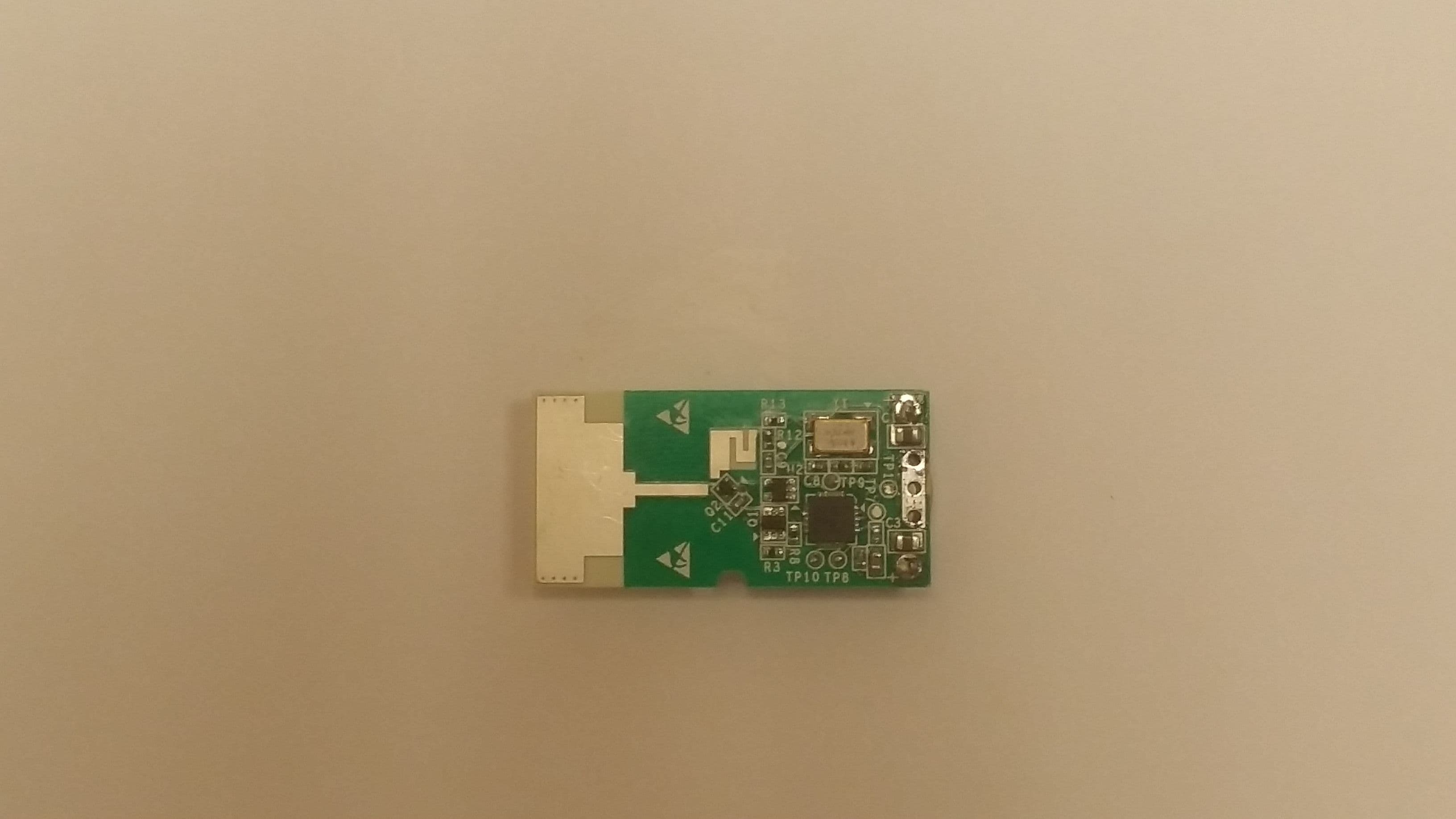
Click to zoom
Application Details
- Equipment Class
- UWB - Ultra Wideband Transmitter
- Date of Grant
- Apr 13, 2015
- Application Purpose
- Original Equipment
- Date of Application
- Mar 22, 2015
- Equipment Note
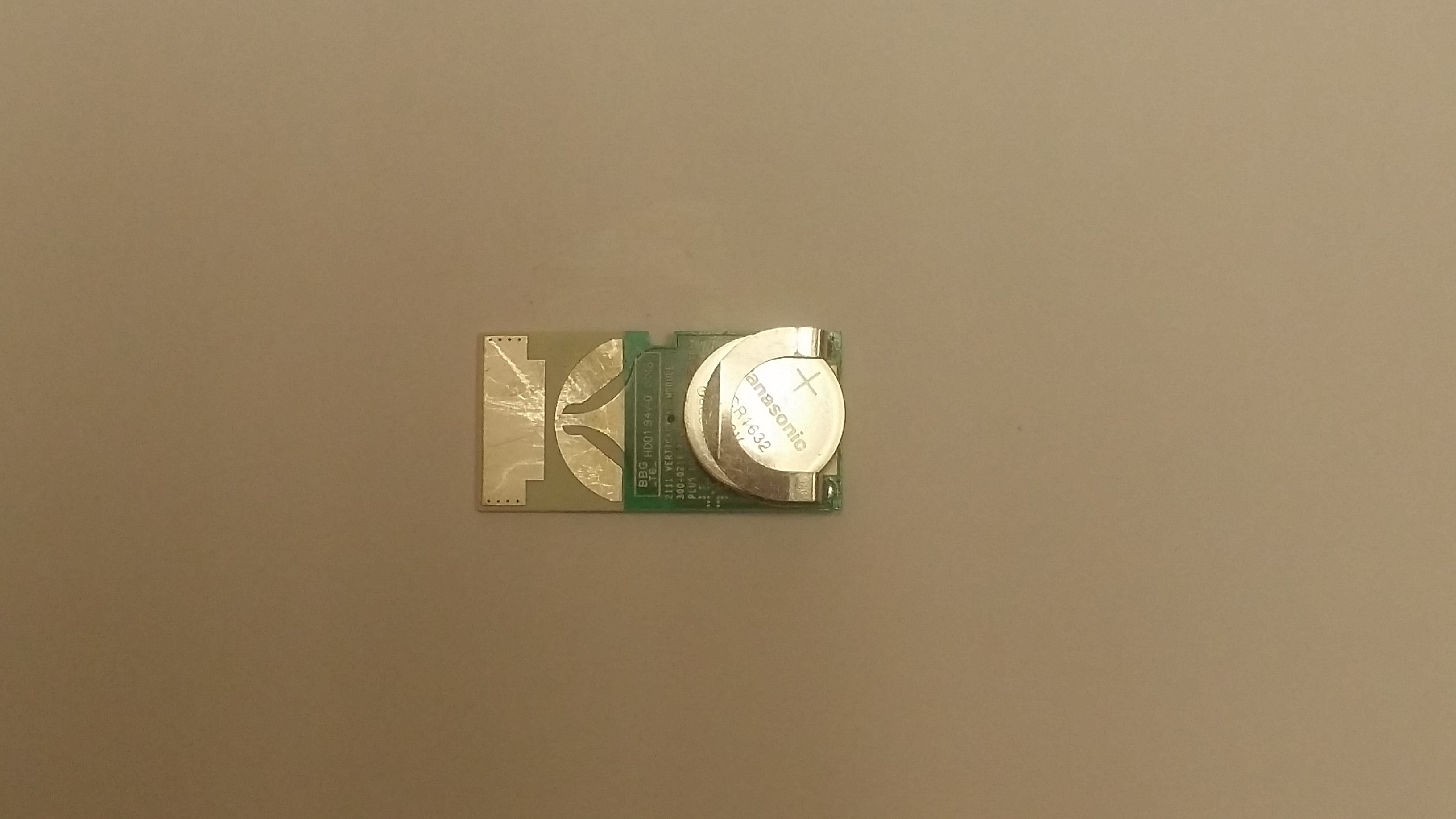
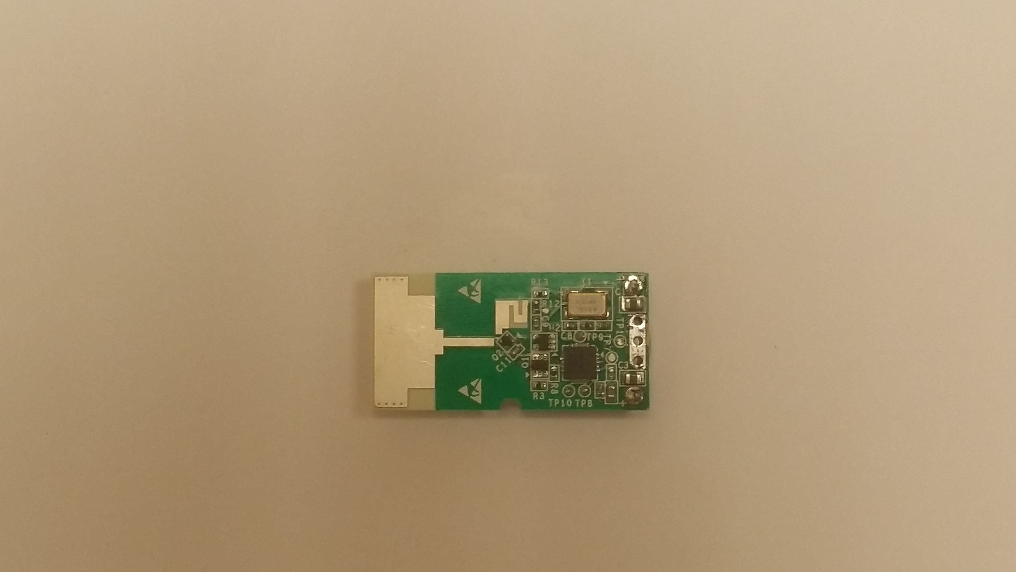
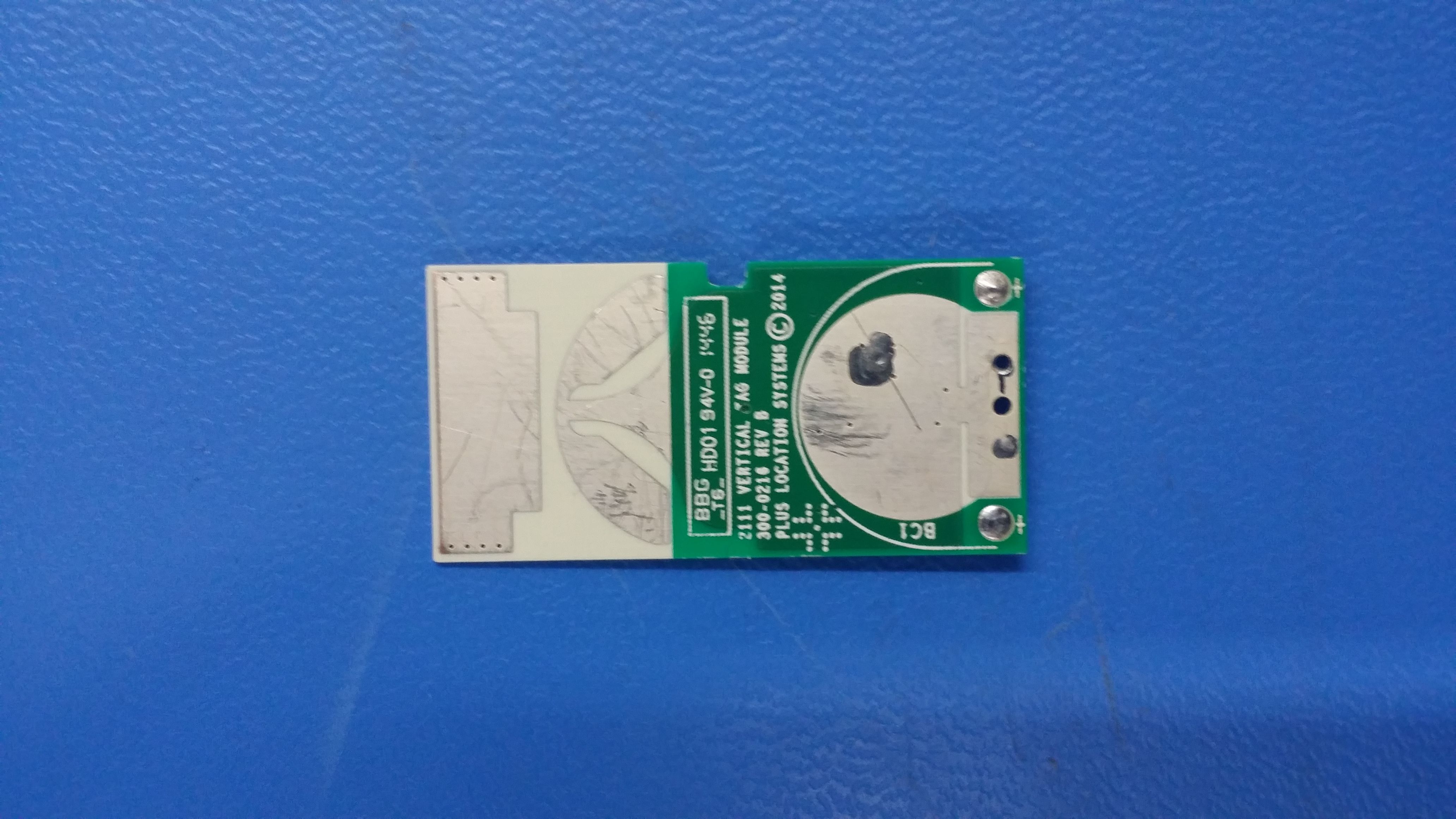
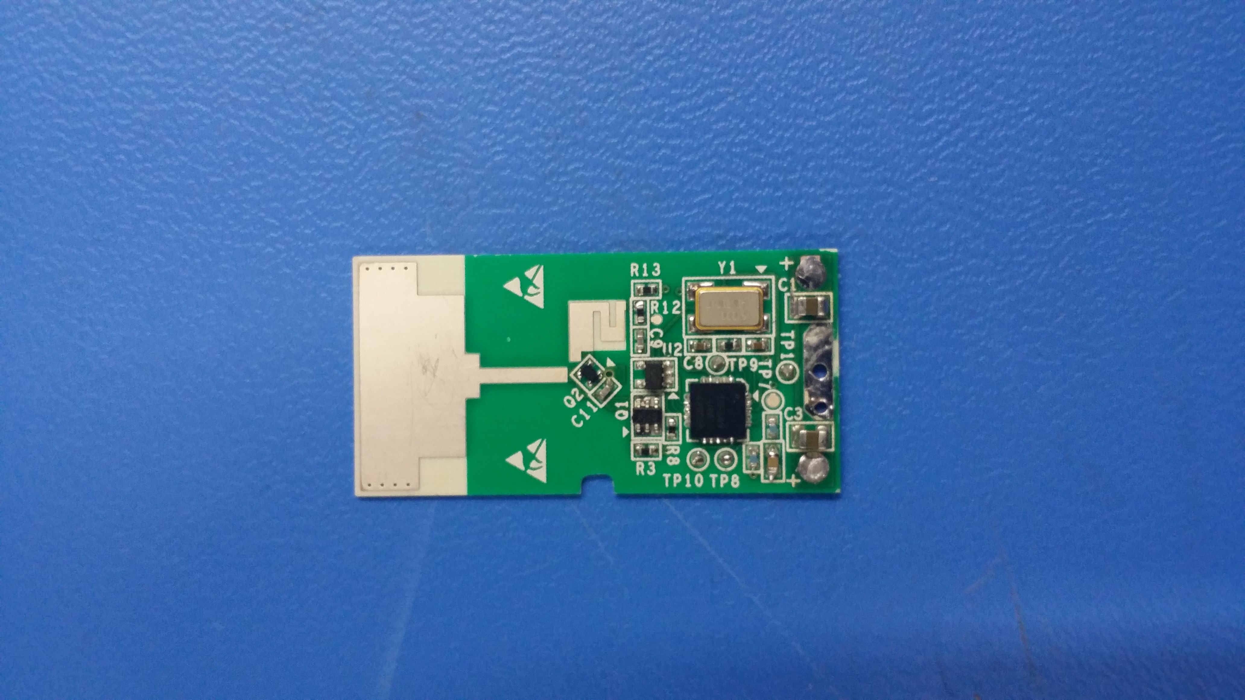
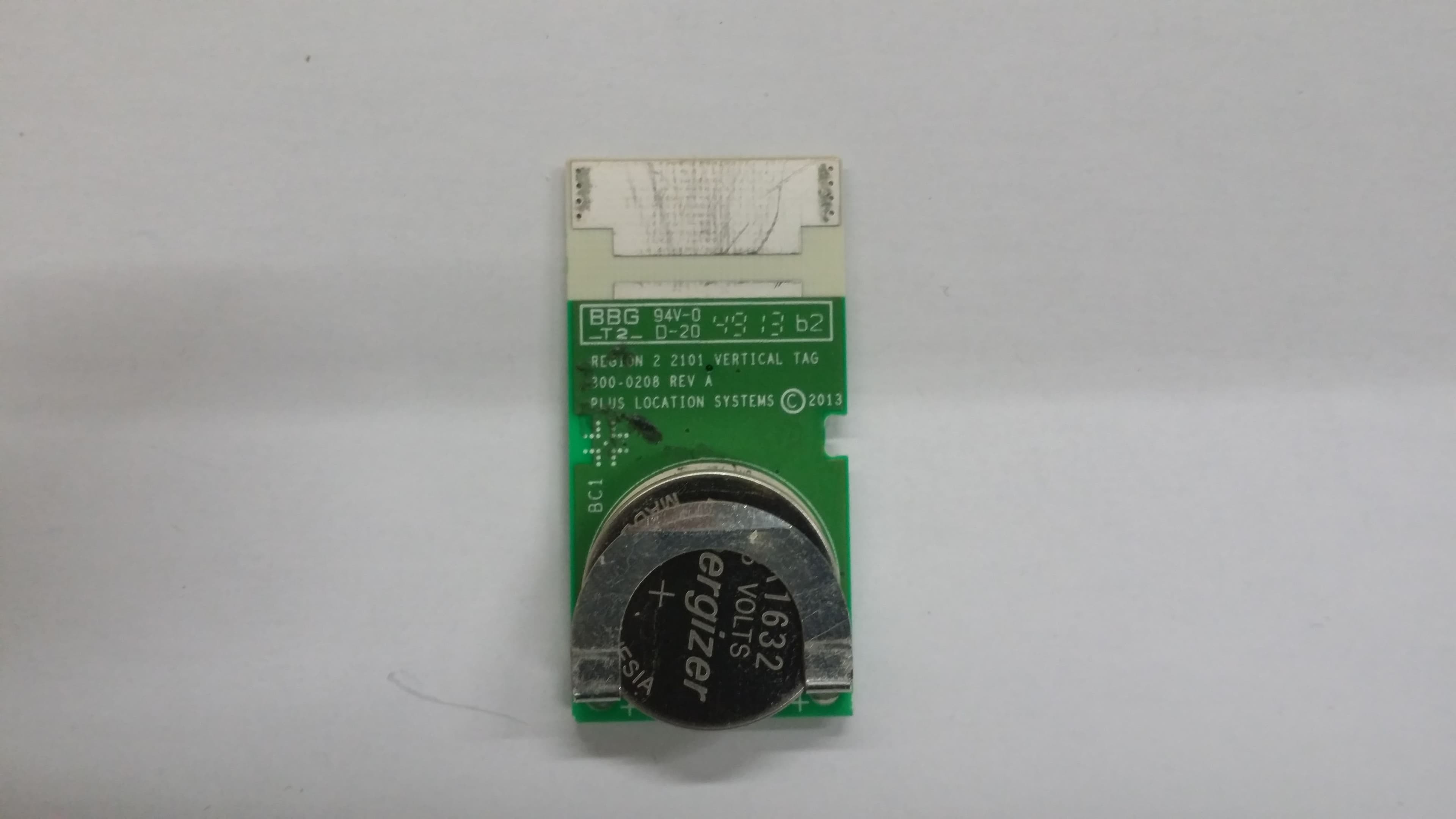
- 2111 Tag Module
- Frequency Range
- 6794.28500000 - 7747.85700000
- Country
- United States
Documents & Files
Document Text
Text extracted from the exhibit documents filed with the FCC. Open a document above to read the original.
Users Manual
PLUS Modular Tag Model 2111 Circuit Implementation Manual Model 2111 Modular Tag Manual Page 2 of 16 Contents Regulatory & Legal Information ............................................................................................................................ 3 Safety Information .................................................................................................................................................. 4 Revisions to this Document .................................................................................................................................... 5 Introduction ............................................................................................................................................................. 6 Overview ................................................................................................................................................................. 7 Specifications .......................................................................................................................................................... 8 Mounting ................................................................................................................................................................. 9 Identification ........................................................................................................................................................... 9 FCC Section 15.212 Compliance .......................................................................................................................... 10 Example ................................................................................................................................................................ 15 End Product ID Recommended Format ................................................................................................................ 16 Model 2111 Modular Tag Manual Page 3 of 16 Regulatory & Legal Information Copyright © PLUS ® Location Systems. No part of this manual may be copied or reproduced without prior written consent from PLUS ® Location Systems. Disclaimer The information in this document is subject to change without notice. PLUS ® Location Services (“PLUS”) assumes no responsibility for inaccuracies or omissions and specifically disclaims any liabilities, losses, or risks, personal or otherwise, incurred as a consequence, directly or indirectly, of the use or application of any of the contents of this document. For the latest documentation, contact your local supplier or visit us online at www.pluslocation.com. Trademarks & Patents PLUS and the PLUS logo are trademarks of PLUS ® Location Systems. Other trademarks and trade names used in this manual are the property of the manufacturers or vendors of the respective products. Intended Use This document examines the PLUS 2111 Modular Tag. This document is intended for PLUS Location Systems internal use only. FCC Compliance U.S. Operation: This device complies with Part 15 of the FCC Rules. Operation is subject to the following conditions: (1) this device may not cause harmful interference, and (2) this device must accept any interference received, including interference that may cause undesired operation. (3) Operation on board an aircraft or a satellite is prohibited. (4) Devices operating under this section may not be employed for the operation of toys. (5) Except for operation onboard a ship or a terrestrial transportation vehicle, the use of a fixed outdoor infrastructure is prohibited. A fixed infrastructure includes antennas mounted on outdoor structures, e.g., antennas mounted on the outside of a building or on a telephone pole. This outdoor infrastructure prohibition applies to intentional ultra-wideband (UWB) emitters. Operation in disregard of these conditions is a violation of 47 U.S.C. 301 and could subject the operator to serious legal penalties. Disassembling or modifying the unit will void both FCC compliance and PLUS ® Location Systems warranty provisions. Manufacturer Contact Information HQ and Regulatory Responsibility: PLUS Location Systems USA, LLC 6767 Old Madison Pike NW, Suite 310 Huntsville, AL 35806 www.pluslocation.com Model 2111 Modular Tag Manual Page 4 of 16 Safety Information Read and follow all instructions before using the Model 2111 Tag when it has been incorporated into an end product. The following are typical safety instructions for a PLUS Tag that would apply to an end product using the 2111 Module. Do not use the Tag if it has been damaged. Do not install in environments that exceed temperature and humidity requirements. Do not leave the Tag on a heat source. Never open the case on the Tag: There are no user serviceable parts or replaceable parts inside the enclosure. Model 2111 Modular Tag Manual Page 5 of 16 Revisions to this Document Version Comments Release Date Rev A Initial release 03/10/2015 Model 2111 Modular Tag Manual Page 6 of 16 Introduction The Plus Model 2111 Modular Tag is a complete PLUS UWB Tag design for integration into a PLUS printed wiring assembly (PWA) and enclosure, and connected to a power source. It has the following features: Runs from a 3 volt DC power source (can operate down to 2 volts DC) Will transmit a UWB packet at a rate set at time of manufacture. Rate can be set to 1Hz, 6Hz, 8Hz, 10Hz, 15Hz or 20Hz. Meets FCC Section 15.212, rules concerning single modular transmitters. Certified to comply with FCC Part 15.519 Model 2111 Modular Tag Manual Page 7 of 16 Overview Background Tag tracking is accomplished by analyzing time-differences-of-arrival (TDOAs) of tag transmissions. When a tag transmits a packet, PLUS ® Sensors that successfully receive the packet will send out information concerning the tag packet, including a precise timestamp. The difference in the timestamp between sensors gives the TDOA for that sensor pair/tag combination. At least three sensors must hear a tag …
Text truncated - open the document above for the full version.
Cover Letter(s)
Cummings Research Park 6767 Old Madison Pike, Suite 310 Huntsville AL 35806 P: +1 256-217-4072 M:+1 256-964-7614 www.pluslocation.com March 10, 2015 Request for Confidential Treatment FCC ID ZEH0215 PLUS Location Systems (PLUS) requests that all schematics be withheld from public disclosure in accordance with Section 0.457 and 0.459 of the Commission’s Rules, 47 C.F.R., following grant of the application. In support of this request, PLUS submits the following: (1) identification of the specific information for which confidential treatment is sought: PLUS Location Systems seeks confidentiality for all schematics of the device. These exhibits are segregated from the non-confidential exhibits of the application. (2) identification of the Commission proceeding in which the information was submitted or a description of the circumstances giving rise to the submission: The proceeding is that involving the application for equipment authorization (certification) under FCC ID ZEH0215. (3) explanation of the degree to which the information is commercial or financial, or contains a trade secret or is privileged: This material includes circuit diagrams and board layout information for the system. As such, this material is treated as highly confidential business information. (4) explanation of the degree to which the information concerns a service that is subject to competition: The material for which confidentiality is sought is employed in the design and manufacture of ultra-wideband tracking systems that are offered on a highly competitive basis. Customers for this equipment have a variety of competing sources of supply. (5) explanation of how disclosure of the information could result in substantial competitive harm: Disclosure would, in effect, give away the fruits of the labors of the engineering department, who have designed the equipment and the manufacturing processes. Disclosure would also offer competitors additional unwarranted insight into the state of product development Cummings Research Park 6767 Old Madison Pike, Suite 310 Huntsville AL 35806 P: +1 256-217-4072 M:+1 256-964-7614 www.pluslocation.com thereby allowing such competitors an advantage that would not be available to them unless they were working with PLUS and had a non-disclosure agreement with PLUS. (6) identification of any measures taken by the submitting party to prevent unauthorized disclosure: The information for which confidential treatment is sought is kept confidential by PLUS and not made available to third parties except pursuant to non-disclosure agreements. (7) identification of whether the information is available to the public and the extent of any previous disclosure of the information to third parties: To the knowledge of those preparing this application, the information has not been disclosed publicly heretofore. The protection sought is narrowly drawn and pertains to certain specific implementations of ultra-wideband technology. (8) justification of the period during which the submitting party asserts that material should not be available for public disclosure: This material should not be disclosed for at least five years. Disclosure of the design information would lead to insights into both designs and manufacturing techniques and could have an adverse competitive effect for many years to come. (PLUS is aware, for example, of overseas competitors for this application.) As this is industrial equipment, we expect the equipment to be used for more than five years in some cases. (9) any other information that the party seeking confidential treatment believes may be useful in assessing whether its request for confidentiality should be granted: See item 8 above. Note that the equipment for which approval is being sought will be employed in applications that inherently carry a premium on security. Respectfully: Keven Trach Vice President, Projects
ID Label/Location Info
SCALE 2 : 1 USE ZEBRA FINT STYLE "R" USE ZEBRA FINT STYLE "Q" USE ZEBRA FONT STYLE "R" BARCODE 0mm 0.000in 1.8mm 0.07in 4.7mm 0.19in 7.4mm 0.29in 10.4mm 0.41in 6.4mm 0.25in 12.7mm 0.50in 0mm 0.000in 15.9mm 0.63in 31.8mm 1.25in NOTES: DRAWING IS TO PROVIDE A TEMPLATE OF REQUIRED INFORMATION FOR FINAL TAG ASSEMBLIES THAT 1. USE THE 2111 TAG MODULE CIRCUIT. IF THE FINAL TAG REQUIRES A DIFFERENT GRAPHICS OR OUTLINE FORMAT THE INFORMATION LISTED MUST BE INCLUDED. TO BE PRINTED ON A ZEBRA THERMAL TRANSFER PRINTER 105SL 300dpi VERSION (P/N 10500-3001-0000 2. OR EQUIVALENT). USE TDC P/N 044-0017-9 FOR PRINTER RIBBON. BAR-CODE TO BE CODE 128A WITH A MINIMUM BAR HEIGHT OF 0.14 AND A BAR RATIO OF 3:1 OR A QR 3. CODE FORMAT. DUE TO CONSTRAINTS RESULTING FROM THE PWA ASSEMBLY AND SERIALIZATION PROCESS THE TAG 4. UNIT SERIALIZATION DOES NOT FOLLOW THE CONCEPT SPECIFIED IN PLUS DOCUMENT NUMBER 450- 0005 "SERIALIZATION GUIDELINES" WHICH IS TYPICAL FOR PLUS LOCATION ASSEMBLIES. THE PWA IS PROGRAMMED WITH AN 8-DIGIT HEX CHARACTER STRING. THOSE EIGHT CHARACTERS ARE TO PRINTED ON THE SERIAL NUMBER LABEL IN BOTH BAR-CODE AND HUMAN READABLE FORM. PRINTED LABEL IS AN OUTPUT OF SOFTWARE P/N 150-0067 "Software, PLUS TAG Functional Test"5. SPECIFIC INFORMATION FOR MODEL NUMBER ARE LISTED ON THE UNIT ASSEMBLY DRAWING FOR THE 6. FINAL PRODUCT (100 LEVEL DRAWING). SCALE 5:1 APPROXIMATE LOCATION OF TEXT. RoHS COMPLIANCE NOTE: ALL MATERIALS, INKS, ADHESIVES, OVERLAMINATES AND PROCESSES USED TO PRODUCE THIS LABEL SHALL COMPLY WITH THE EU DIRECTIVE 2002/95/EC ON THE RESTRICTION OF THE USE OF CERTAIN HAZARDOUS SUBSTANCES IN ELECTRICAL AND ELECTRONIC EQUIPMENT (RoHS). SUPPLIER SHALL ALSO RETAIN DOCUMENTATION SUPPORTING RoHS COMPLIANCE ACCORDING TO THEIR STANDARD OPERATING PROCEDURES. ANY DEVIATIONS FROM THIS REQUIREMENT MUST BE OBTAINED IN WRITING FROM PLUS LOCATION SYSTEMS. REVISIONS ZONEREV.DESCRIPTIONDATEAPPROVED ~AINITIAL RELEASE2014/3/12JA 6767 OLD MADISON PIKE NW SUITE 310 HUNTSVILLE, AL 35806 USA 320-0309 3rd ANGLE PROJECTION DO NOT SCALE DRAWING THE INFORMATION CONTAINED IN THIS DRAWING IS THE SOLE PROPERTY OF PLUS LOCATION SYSTEMS. ANY REPRODUCTION IN PART OR AS A WHOLE WITHOUT THE WRITTEN PERMISSION OF PLUS LOCATION SYSTEMS IS PROHIBITED. PROPRIETARY AND CONFIDENTIAL PRIMARY DIMENSIONS ARE IN MILLIMETERS TOLERANCES: ANGULAR: MACH BEND ONE PLACE DECIMAL TWO PLACE DECIMAL THREE PLACE DECIMAL MATERIAL FINISH MAKE FROM P/N 044-0037-9 COMMENTS: DATE NAME TITLE: SIZE B PART NUMBER REV SCALE: 5:1 UNLESS OTHERWISE SPECIFIED JOE ANDERSON3/12/2015 Template PLUS 2111 TAG Module SHEET 1 OF 1 A .01 .005 .0005 SECONDARY DIMENSIONS ARE IN INCHES TOLERANCES: ANGULAR: TWO PLACE DECIMAL THREE PLACE DECIMAL FOUR PLACE DECIMAL 0.3 0.15 0.015 1.0 0.50.5 A-01 DRAWN BY DESIGNED BY JOE ANDERSON3-12-2015
Operational Description
Cummings Research Park 6767 Old Madison Pike, Suite 310 Huntsville AL 35806 P: +1 256-217-4072 M:+1 256-964-7614 www.pluslocation.com March 10, 2015 Theory of Operation / Technical Description The PLUS tracking system is a Real-Time Location System (RTLS) based on Ultra Wideband (UWB) technology. Its primary use is for the location and identification of people or objects. The system operates using active tags, a network of sensors (receivers), and one or more Synchronization Distribution Panels (SDPs). Sensor: The PLUS sensors are receive-only devices that are permanently mounted in the area of coverage. The sensors listen for and decode data packets from the tag, and also ascertain the time of arrival of the packet. Synchronization Distribution Panel: The synchronization distribution panel (SDP) distributes a timing signal to the multiple sensors in order that the times of arrival measured by each have a common time base. The SDP additionally powers the sensors over Ethernet cable, and passes the decoded data and measured times of arrival to other Ethernet devices. Tag, PLUS Model Number 2111 (FCC ID: ZEH0215): The Tag is a small, transmit-only device with an active transmit duty cycle of less than 0.0026%. The Tag has one integrated antenna optimized for vertical applications. The data packets include a tag identification code, status information, and time of arrival data.
Operational Description
6767 Old Madison Pike NW, Suite 310, Huntsville AL 35806 Main: 256.217.4072 Fax: 256.964.7614 2111 Single Limited Modular Transmitter Integration, Usage Limitations, and Grant Comments Scope This document identifies the integration requirements and usage limitations of the 2111 Single Limited Modular Transmitter as required by FCC 15.212 and KDB 996369. Pertinent grant comments as identified in KDB 821551 are also identified Integration Requirements 1. The 2111 Single Limited Modular Transmitter (2111 Module) shall be used PLUS Location Systems USA, LCC (PLUS), for integration into its own host devices. The 2111 Module shall not be sold or otherwise provided to third parties for integration into other devices. Third parties are prohibited from modifying the 2111 Module or integrating the 2111 Module into any host device. 2. Integration requirements provided herein shall be strictly followed by PLUS when incorporating the 2111 Module into any host device. 3. The 2111 Module includes an integrated antenna which shall not be modified as part of the integration into host devices. 4. The 2111 Module circuit board and active hardware components that determine transmitted signal radio parameters (such as output power and frequency) shall not be modified as part of the integration process into host devices. 5. The 2111 Module shall operate from a nominal 3 VDC power source provided by the host device. When integrated into the host product, the 2111 Module shall not be modified to operate at other voltages. 6. The 2111 Module shall be integrated into a host device utilizing an enclosure to provide physical protection for the internal components. The 2111 Module shall not rely on properties of the host device enclosure to meet emission limitations. The host device enclosure may vary in size, thickness and material type provided that all grant limitations are maintained. 7. The 2111 Module transmit signal characteristics shall not be controlled or modified by any external interface or user input mechanism. 8. The 2111 Module transmit signal characteristics shall not be controlled or modified by any autonomous (internally software managed) process. 9. The 2111 Module shall be labelled with its FCC ID number. 10. All 2111 Module host devices shall include a label identifying the FCC ID of the internal 2111 Module. 11. All 2111 Module host devices shall comply with all applicable FCC equipment authorizations regulations, requirements and equipment functions not associated with the transmitter module portion. 6767 Old Madison Pike NW, Suite 310, Huntsville AL 35806 Main: 256.217.4072 Fax: 256.964.7614 Grant Comments 1. The 2111 Module and any host device shall comply with transmitted power limits as identified in FCC 15.519 (i.e. in-band EIRP not to exceed -41.3 dBm/MHz). As the 2111 Module has been lab tested for compliance with the 15.519 limits, and no user controls or modifications to the transmitted signal are enabled, compliance with these limits is maintained. 2. The 2111 Module includes an integrated antenna. The host device shall not provide a mechanism for disconnecting, changing, or bypassing the integrated antenna. 3. The 2111 Module and host device duty cycle factor shall be limited by factory firmware settings. 4. The 2111 Module and host devices may not be employed for the operation of toys. 5. Operation onboard an aircraft, a ship or a satellite is prohibited.
Operational Description
6767 Old Madison Pike NW, Suite 310, Huntsville AL 35806 Main: 256.217.4072 Fax: 256.964.7614 March 20, 2015 To whom it may concern, This correspondence addresses information required as part of the request for a modular grant of FCC ID ZEH0215, as described in KDB Publication 996369 D01. Scope The approval request is for a Limited Single-Modular Transmitter approval for a device with FCC ID ZEH0215. Limitations for Third Parties As a Limited Single-Modular Transmitter, the integration of the module and qualification of each host device product will be controlled by PLUS Location Systems USA, LLC (PLUS). PLUS will only sell or provide completed host products to third parties. PLUS will not provide modules to third parties or enable third parties to integrate the modules. Note that a contract manufacturer building products according to PLUS’ specifications is considered to be working under the direction of PLUS, not as an independent third party. Software Control and Software Defined Radios For clarification, this device is not a Software Defined Radio (SDR). Additionally, no software parameters are accessible or controllable to set power levels or other characteristics of the device that influence compliance. Host Product Compliance Any host product equipment functions not associated with the transmitter module (such as unintentional radiator elements) will be independently tested for compliance. Testing of the host product will be performed with the module installed and operational. Module as a Printed Wiring Assembly (PWA) The Limited Module is implemented as a physical Printed Wiring Assembly (PWA) with two electrical connections; a ground connection and 3V DC power. 6767 Old Madison Pike NW, Suite 310, Huntsville AL 35806 Main: 256.217.4072 Fax: 256.964.7614 Non-Accessible Module The Limited Module integrated into the host device will not be accessible or replaceable by end users. Integration Instructions PLUS will maintain product assembly documentation for the Limited Module and host products for use by itself and its contract manufacturer. The Limited Module will not be made available to third parties for integration. Sincerely, Keven Trach Vice President of Projects 6767 Old Madison Pike Suite 310 Huntsville, AL 35806 P: +1 256-217-4072 M:+1 256-428-6388 www.pluslocation.com
Test Report
Test Report Number: 3692330EMC01 Rev:1 PLUS Location Systems / UWB Tag Page: 1 of 25 Remarks: This report details the results of the testing carried out on one sample, the results contained in this test report do not relate to other samples of the same product. The manufacturer should ensure that all products in series production are in conformity with the product sample detailed in this report. This report may only be reproduced and distributed in full. If the product in this report is used in any configuration other than that detailed in the report, the manufacturer must ensure the new system complies with all relevant standards. Any mention of SGS International Electrical Approvals or Testing done by SGS International Electrical Approvals in connection with distribution or use of the product described in this report must be approved by SGS international Electrical Approvals in writing. EMC Test Report Project Number: 3692330 Report Number: 3692330EMC01 Revision Level: 1 Client: PLUS Location Systems Equipment Under Test: PLUS Transmit only UWB Tag Model Name: Tag Module Model Number 2111 Applicable Standards: FCC Part 15.519 Report issued on: 28 February 2015 Test Result: Compliant Tested by: David Schramm, EMC/RF/SAR/HAC Manager Reviewed by: Jeremy O. Pickens, Senior EMC Engineer Test Report Number: 3692330EMC01 Rev:1 PLUS Location Systems / UWB Tag Page: 2 of 25 SGS North America Inc. Consumer Testing Services 620 Old Peachtree Road NW, Suite 100, Suwanee, GA 30024 t (770) 570-1800 www.us.sgs.com/cts Member of the SGS Group (SGS SA Table of Contents 1 SUMMARY OF TEST RESULTS ..................................................................................................................................... 3 1.1 MODIFICATIONS REQUIRED TO COMPLIANCE ................................................................................................................ 3 2 GENERAL INFORMATION ............................................................................................................................................. 3 2.1 CLIENT INFORMATION ................................................................................................................................................... 3 2.2 TEST LABORATORY ....................................................................................................................................................... 3 2.3 GENERAL INFORMATION OF EUT .................................................................................................................................. 3 2.4 OPERATING MODES AND CONDITIONS .......................................................................................................................... 3 2.5 EUT BLOCK DIAGRAM .................................................................................................................................................. 4 3 RADIATED EMISSIONS BELOW 1 GHZ ...................................................................................................................... 5 3.1 TEST RESULT ................................................................................................................................................................. 5 3.2 TEST METHOD ............................................................................................................................................................... 5 3.3 TEST SITE ...................................................................................................................................................................... 6 3.4 TEST EQUIPMENT .......................................................................................................................................................... 6 3.5 TEST SETUP PHOTOGRAPHS ........................................................................................................................................... 7 3.6 TEST DATA .................................................................................................................................................................... 8 4 BANDWIDTH REQUIREMENTS .................................................................................................................................... 9 4.1 TEST RESULT ................................................................................................................................................................. 9 4.2 TEST METHOD ............................................................................................................................................................... 9 4.3 TEST SITE ...................................................................................................................................................................... 9 4.4 TEST EQUIPMENT .......................................................................................................................................................... 9 4.5 TEST SETUP PHOTOGRAPHS ......................................................................................................................................... 10 4.6 TEST DATA .................................................................................................................................................................. 11 5 PEAK POWER WITHIN A 50 MHZ BANDWIDTH ................................................................................................... 12 5.1 TEST RESULT ............................................................................................................................................................... 12 5.2 TEST METHOD ............................................................................................................................................................. 12 5.3 TEST SITE .......................................................................................................................................…
Text truncated - open the document above for the full version.
Contact Information
Applicant
Keven Trach(V.P. of Projects)
Technical Contact
PLUS LocationSean Minor
[email protected]256 694 8301
6767 Old Madison Pike NW · Huntsville, Alabama · United States
Non-Technical Contact
PLUS LocationKeven Trach
[email protected]256 428 6388
Test Firm
SGS North America, Inc.David Schramm
Technical Specifications
| # | Rule Parts | Frequency Range | Power Output |
|---|---|---|---|
| 1 | 15F | 6.79 GHz - 7.75 GHz | - |
Other Applications from PLUS Location Systems USA LLC.
ZEH0414
Sep 29, 20142110 Tag Module
Equipment Class
UWB - Ultra Wideband Transmitter
ZEH0412
Jun 10, 2012WBT Tag
Equipment Class
WBT - Wideband Transmitter
ZEH1211
Feb 08, 2012Asset Tag
Equipment Class
WBT - Wideband Transmitter