ZGID9190A01Dimming Switch module
Airline Mechanical Co., Ltd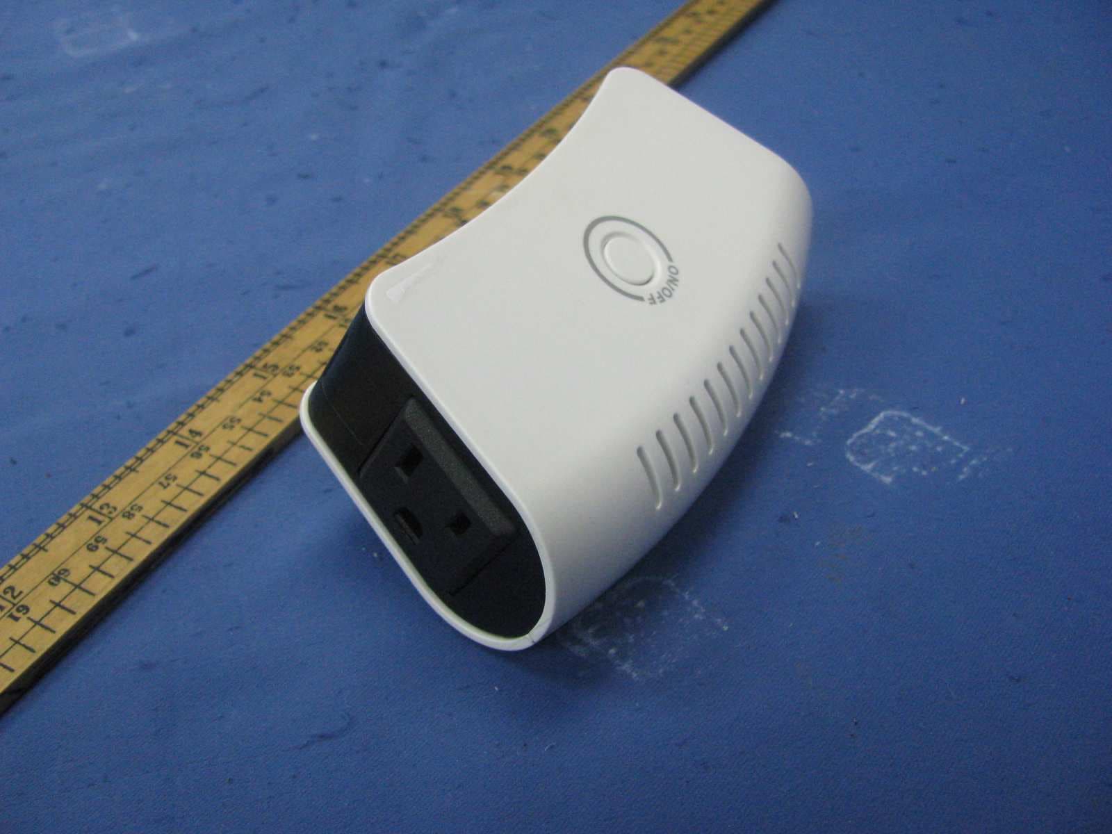
Click to zoom
Application Details
- Equipment Class
- DXT - Part 15 Low Power Transceiver, Rx Verified
- Date of Grant
- Apr 11, 2011
- Application Purpose
- Original Equipment
- Date of Application
- Apr 11, 2011
- Equipment Note
- Dimming Switch module
- Frequency Range
- 908.42000000 - 908.42000000
- Company
- Airline Mechanical Co., Ltd
- Country
- Hong Kong
Documents & Files
Document Text
Text extracted from the exhibit documents filed with the FCC. Open a document above to read the original.
Users Manual
~1~ Rev 02 2011/01/19 Wireless Lighting Control ZDS-UD10 A01 Dimming Switch Module USER MANUAL Rev. 0 Z-Wave®Certified Wireless Lighting Control ~2~ Rev 02 2011/01/19 Introduction: Thank you for choosing AMC (Airline Mechanical Co., Ltd) Z-Wave® control product. Our Z-Wave® enabled product allows user to remotely control lighting, home appliance, and make home control easy at low installation / maintenance cost. You may begin with a few Z-Wave® enabled devices or build up a complete home automation system with our products. The AMC Plug-in Dimming Switch Lamp Module is a Z-Wave® enabled device and fully compatible with any Z-Wave® enabled network. It allows remote Dimming or On/Off control of specified lamps; Each module is designed to act as a repeater, which will re-transmit the RF signal to ensure that the signal is received by its intended destination by routing the signal around obstacle and radio dead spots. Certifications UL Listed: This power unit is intended to be correctly orientated in a vertical or floor mount position. FCC Information FCC ID : Z GID9190A01 Th is device complies with Part 15 of the FCC Rules. Operation is subject to the following two conditions: (1) this device may not cause harmful interference, and (2) this device must accept any interference received, including interference that may cause undesired operation. Warning: Changes or modifications to this unit not expressly approved by the party responsible for compliance could void the user’s authority to operate the equipment. NOTE: This equipment has been tested and found to comply with the limits for a Class B digital device, pursuant to Part 15 of the FCC Rules. These limits are designed to provide reasonable protection against harmful interference in a residential installation. This equipment generates, uses and can radiate radio frequency energy and, if not installed and used in accordance with the instructions, may cause harmful interference to radio communications. ~3~ Rev 02 2011/01/19 However, there is no guarantee that interference will not occur in a particular installation. If this equipment does cause harmful interference to radio or television reception, which can be determined by turning the equipment off and on, the user is encouraged to try to correct the interference by one or more of the following measures: Reorient or relocate the receiving antenna. Increase the separation between the equipment and receiver. Connect the equipment into an outlet on a circuit different from that to which the receiver is connected. Consult the dealer or an experienced radio/TV technician for help. Specification Rating Input:120Vac, 60Hz; total power: 1400W max. Signal (Frequency) 908.42 MHz Output Outlet: Double outlets, one Z-Wave controllable outlet, and the other is “Always On” pass through outlet. A: For Max Output power of Z-Wave controlled outlet (Slide Switch for DIMMER(Dimming/ON/OFF mode) or SWITCH(ON/OFF) mode selected ): 1. DIMMER Mode (slide switch to dimmer location): Max 330W, 2.75A, Incandescent load. 2. SWITCH Mode(slide switch to Switch location): a. Max 330W, 2.75A, Incandescent Load ٛ. b. Max 500W, 4.16A, Resistive Load B: “Always On” pass through outlet: Max Power of 1200W, 10A, Resistive load. C: Total for both Z-Wave Outlet and “Always on” Pass through outlet: Max 1400W, 120Vac, Resistive load D: Range: Up to 20m line of sight between the Wireless Controller and the closest Z-Wave receiver module. E: DIMMER mode: Can only be connected to incandescent lamp, Resistive. F: SWITCH mode: Can be connected to incandescent lamp, Resistive. Over Temperature protection: Detected internal temperature, and cut off output ~4~ Rev 02 2011/01/19 once OTP triggered. (Remark: Under Over loading or Over Temperature situation, it will fail to start up). EMC: Meet FCC Pa rt15 B, C Sa fety: Meet UL244A standard Z-Wave: Recognized Body Color: Milk white or other Reference Dimension(L x W x H): 126X68X40mm Reference Weight: about 180g Storage:-10~60°C Operation Temperature:-10~40°C Relative Humidity:5~95% Environment: Only for indoor use Specifications subject to change without notice due to continuing product improvement Glossary Device/Light/Node Devices, lights and nodes are all terms to describe an individual Z-Wave device. These are all interchangeable when setting up your Z-Wave network. Inclusion Add a Z-Wave device to the network. Delete a Z-Wave device from the Exclusion network. A collection of Z-Wave devices configured to turn to a specific level, Scene setting, mode, or perform an operation. Scenes are usually activated by a controller, timed event, or specific conditions. Associations are used to set up one node to automatically contact another node when the first is triggered. For example Association you can set up a door sensor (primary node) to turn on the light (secondary node) when the door has been opened. ~5~ Rev 02 2011/01/19 Key Features: - Support Scene control (Dimmer mode ONLY) - Selective slide switch for DIMMER/SWITCH mode -Fine appearance designed - High output power in SWITCH mode - High output power in DIMMER mode - One Z-wave controlled AC outlet for standard incandescent lighting. - One Always-ON pass-through AC outlet - Remote ON/OFF and Brightness control via the Z-Wave controller - Manual ON/OFF and Brightness control with the front panel push button - Space efficient design - Does not block the lower outlet when plugged into the upper outlet of a duplex wall receptacle. (This assumes that the duplex receptacle is mounted with the ground pin down.) - Plugs and cords for connected devices route to the side allowing close placement of furniture - Grounded 3-wire power connection for safety - Over temperature protection - Over current/Loading protection under Switch Mode A ... ON/OFF/DIMMER Push button ~6~ Rev 02 2011/01/19 B ... Always on outlet C ...Z-Wave controlled outlet D ... AC input prong E ... Selective slide switch (On/Off or Dimming Model) Warning: The incande…
Text truncated - open the document above for the full version.
Cover Letter(s)
ZGID9190A01
External Photos
External Photos
Internal Photos
Internal Photos
Test Setup Photos
Conducted Photos
Test Setup Photos
Radiated Photos
Contact Information
Applicant
Dominic Cheng
Technical Contact
Intertek Testing Services Shenzhen Ltd KejiyuanShawn Xing
[email protected]86-755-8614 0603
6F, D Block, Huahan Building, · Shenzhen · China
Non-Technical Contact
Intertek Testing Services Shenzhen Ltd KejiyuanShawn Xing
[email protected]86-755-8614 0603
Test Firm
Intertek Testing Services Shenzhen Ltd.Shawn Xing
Technical Specifications
| # | Rule Parts | Frequency Range | Power Output |
|---|---|---|---|
| 1 | 15C | 908.42 MHz - 908.42 MHz | - |
Other Applications from Airline Mechanical Co., Ltd

ZGIDA065
Jul 25, 2012Remote wall switch with Z-WAVE
Equipment Class
DXT - Part 15 Low Power Transceiver, Rx Verified