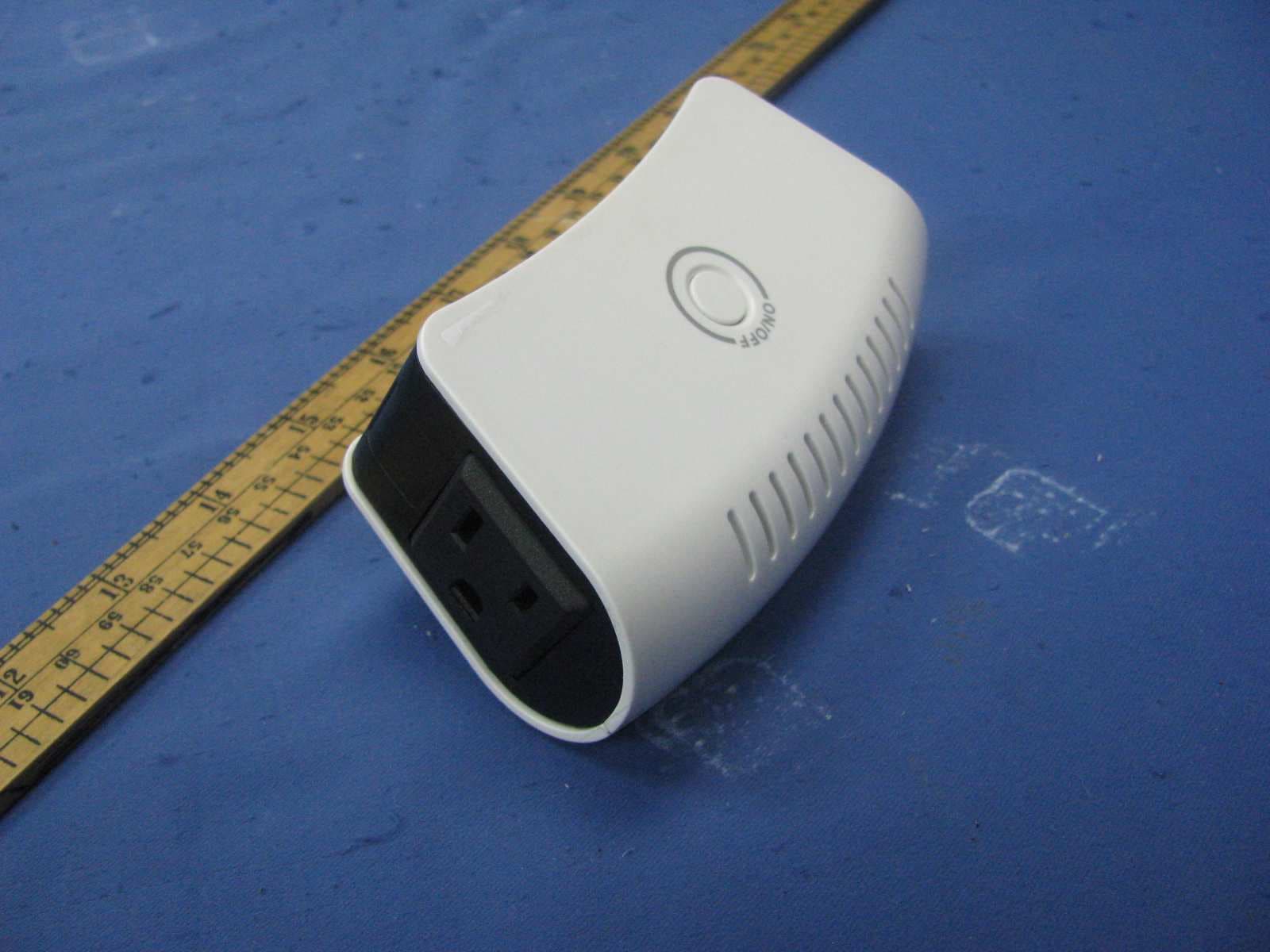
ZGIDA065Remote wall switch with Z-WAVE
Airline Mechanical Co., Ltd
Click to zoom
Application Details
- Equipment Class
- DXT - Part 15 Low Power Transceiver, Rx Verified
- Date of Grant
- Jul 25, 2012
- Application Purpose
- Original Equipment
- Date of Application
- Jul 25, 2012
- Equipment Note
- Remote wall switch with Z-WAVE
- Frequency Range
- 908.42000000 - 908.42000000
- Company
- Airline Mechanical Co., Ltd
- Country
- Hong Kong
Documents & Files
Document Text
Text extracted from the exhibit documents filed with the FCC. Open a document above to read the original.
Users Manual
Page 1 of 14 Wireless Control ZFM-M80US/DB038 Z-Wave Smart Fixture Switch Module (with switch and energy meter) USER MANUAL Introduction: Thank you for choosing ZFM-M80US Z-Wave control product. Our Z-Wave enabled product allows user to remotely control resistive household appliance with power metering feature, and make home control easy at low installation / maintenance cost. You may begin with a few Z-Wave enabled devices or build up a complete home automation system with our products. The ZFM-M80US Smart Fixture Switch Module (with switch and energy meter) is a Z-Wave enabled device and fully compatible with any Z-Wave enabled network. It allows remote On/Off control of specified resistive household appliance, report instant power consumption (W) and accumulated energy consumption (Wh) to gateway device. Each Smart Fixture Switch Module is designed to act as a repeater, which will re-transmit the RF signal to ensure that the signal is received by its intended destination by routing the signal around obstacle and radio dead spots. Page 2 of 14 Glossary Device/Light/Node Devices, lights and nodes are all terms to describe an individual Z-Wave device. These are all interchangeable when setting up your Z-Wave network. Z-Wave Network A collection of Z-Wave devices is controlled by primary and secondary controllers operating on the same system. A Z-Wave network has its own unique ID code so that controllers not in the network cannot control the system. Inclusion Add a Z-Wave device to the network. Exclusion Delete a Z-Wave device from the network. Network Wide Inclusion (NWI) Network Wide Inclusion (NWI) enables both end-user friendly, Plug and Play like Z-Wave network installation as well as professional installation scenario where the inclusion process in terms of time will be reduced significantly. NWI is a feature supported by a new frame type named Explorer which enables the Z-Wave protocol to implement Adaptive Source Routing. Association Association is used to organize nodes in different groups allowing the device to identify the nodes by a group identifier. The groups can also be copied to other devices. Key Features: - High output power - Energy meter for monitoring power consumption. - Remote ON/OFF control via the Z-Wave controller - Manual ON/OFF control with the front panel push button - Support External ON/OFF key connects to the module - Advanced function - Conditional trigger for “Fail Safe Application” - Support Network Wide Inclusion (NWI) and Explore Frames - Screw terminals for wires connection - Flexible mounting structure – mount inside gang box or any place Page 3 of 14 Product Overview: A Mount B Status LED C ON/OFF/PROG Push button D External switch (S/W) E Z-Wave controlled output (isolated relay, RL) F AC input (L, N) A B C D E F Page 4 of 14 Installation DANGER! SHOCK HAZARD. Read and understand these instructions before installing. This device is intended for installation in accordance with the National Electric code and local regulations in the United States, or the Canadian Electrical Code and local regulations in Canada. It is recommended that a qualified electrician perform this installation. For indoor use only in a dry location. Retain instructions for future use. WARNING: To reduce the risk of fire or electric shock, install in a controlled environment relatively free of contaminants. To avoid fire, shock, or death; turn off power at circuit breaker or fuse and test that power is off before wiring! Identifying your wiring application: refer to figure 1 NOTE: If the wiring in the wall box does not resemble any of above configurations, consult a qualified electrician. Connecting wires: refer to figure 1 and connect the wires with correct symbols. Use at less 75°C copper wire only and the stripped wire end’s length must be 9mm. The tightening torque must be 3.5lb-in. (Make sure all wires are firmly fixed at all terminals) CAUTION : Risk of Electric Shock – More than one disconnect switch may be required to de-energize the equipment before servicing. Step 1 Step 2 Step 3 Page 5 of 14 S/W S/W RL RL N L S/W S/W External Switch Page 6 of 14 Single switch (connected with input AC power source for the load) (Important: The relay terminals MUST be connected to L and Load as Figure 1) Figure 1 Warning The resistive household appliance connected into the Z-Wave controlled outlet on this module must not exceed 230Vac 10A or 120Vac 15A. N L External switch Load Page 7 of 14 External Switch ZFM-M80US provides an option to user that can add an external switch to control the On/Off function. ZFM-M80US can be placed into the switch box with external wall switch cover. User can configure the external switch type through the configuration command. Configuration Command for External Switch Parameter Number Definitions 1 (0x01) Set External switch type Parameter Value Definitions 0 (0x00) Disable External switch 1 (0x01) Type A: Tact switch (normal open) Example: 2 (0x02) Type B: Tact switch (normal close) Example: 3 (0x03) Type C: Rocker switch (short = On; open = Off), default Example: 4 (0x04) Type D: Rocker switch (short = Off, open = On) Example: Parameter Table Page 8 of 14 Advanced function “Conditional trigger for Fail Safe Application” ZFM-M80US provides an advanced function “Conditional trigger for Fail Safe Application”. It can turn on or turn off the relay if ZFM-M80US has not received any Z-Wave commands from a specified Z-Wave Node ID and within a specified period. For example: Z-Wave gateway can monitor a Z-Wave device status and power on equipment if this Z-Wave device is out of service. Configuration Command for “Conditional trigger for Fail Safe Application” Parameter Number Definitions Parameter value range 2 (0x02) Set timeout period 0 ~ 240 (minutes) (default value is 0 [function disabled]) 3 (0x03) Configure Node ID number for Z-Wave command source 1 ~ 232 (Node ID number) (default value is 0 [function disabled]) 4 (0x04) Set relay output status if timeou…
Text truncated - open the document above for the full version.
External Photos
External Photos
ID Label/Location Info
字宽18.8mm 字宽18.8mm 字宽18.8mm 字宽18.8mm
Internal Photos
Internal Photos Model: DB038 / ZFM-M80US (with energy power meter function) Model: DA065 / ZFM-80US (without energy power meter function)
Test Report
• The test results reported in this test report shall refer only to the sample actually tested and shall not refer or be deemed to refer to bulk from which such a sample may be said to have been obtained. • This report is for the exclusive use of Intertek's Client and is provided pursuant to the agreement between Intertek and its Client. Intertek's responsibility and liability are limited to the terms and conditions of the agreement. Intertek assumes no liability to any party, other than to the Client in accordance with the agreement, for any loss, expense or damage occasioned by the use of this report. Only the Client is authorized to copy or distribute this report. Any use of the Intertek name or one of its marks for the sale or advertisement of the tested material, product or service must first be approved in writing by Intertek. The observations and test results referenced from this report are relevant only to the sample tested. This report by itself does not imply that the material, product, or service is or has ever been under an Intertek certification program. • For Terms And Conditions of the services, it can be provided upon request. • The evaluation data of the report will be kept for 3 years from the date of issuance. TRF No.: FCC 15C_Tx_b Intertek Testing Services Shenzhen Ltd. Kejiyuan Branch 6F, D Block, Huahan Building, Langshan Road, Nanshan District, Shenzhen, P. R. China Tel: (86 755) 8601 6288 Fax: (86 755) 8601 6751 Website: www.china.intertek-etlsemko.com Airline Mechanical Co., Ltd Application For Certification FCC ID: ZGIDA065 Remote wall switch with Z-WAVE Model: DB038 Additional Model: DA065, ZFM-80US, ZFM-M80US Transceiver Report No.: SZ12060359-1 We hereby certify that the sample of the above item is considered to comply with the requirements of FCC Part 15, Subpart C for Intentional Radiator, Mention 47 CFR [ 10-1-11] Prepared and Checked by: Approved by: Sign on file Andy Yan Engineer Billy Li Supervisor Date: July 14, 2012 INTERTEK TESTING SERVICES Report No: SZ12060359-1 FCC ID: ZGIDA065 TRF No.: FCC 15C_TX_b i LIST OF EXHIBITS INTRODUCTION EXHIBIT 1: General Description EXHIBIT 2: System Test Configuration EXHIBIT 3: Emission Results EXHIBIT 4: Equipment Photographs EXHIBIT 5: Product Labelling EXHIBIT 6: Technical Specifications EXHIBIT 7: Instruction Manual EXHIBIT 8: Miscellaneous Information EXHIBIT 9: Test Equipment List INTERTEK TESTING SERVICES Report No: SZ12060359-1 FCC ID: ZGIDA065 TRF No.: FCC 15C_TX_b ii MEASUREMENT/TECHNICAL REPORT Airline Mechanical Co., Ltd - Model: DB038 Additional Model: DA065, ZFM-80US, ZFM-M80US FCC ID: ZGIDA065 July 14, 2012 This report concerns (check one:) Original Grant X Class II Change Equipment Type: DXT - Part 15 Low Power Transceiver, RX Verified Deferred grant requested per 47 CFR 0.457(d)(1)(ii)? Yes No X If yes, defer until: date Company Name agrees to notify the Commission by: date of the intended date of announcement of the product so that the grant can be issued on that date. Transition Rules Request per 15.37? Yes No X If no, assumed Part 15, Subpart C for intentional radiator − the new 47 CFR [10-1-11 Edition] provision. Report prepared by: Billy Li Intertek Testing Services Shenzhen Ltd. Kejiyuan Branch 6F, Block D, Huahan Building, Langshan Road, Nanshan District, Shenzhen, P. R. China Phone: (86 755) 8601 6288 Fax: (86 755) 8601 6751 INTERTEK TESTING SERVICES Report No: SZ12060359-1 FCC ID: ZGIDA065 TRF No.: FCC 15C_TX_b iii Table of Contents 1.0 General Description............................................................................................ 2 1.1 Product Description ............................................................................................ 2 1.2 Related Submittal(s) Grants ............................................................................... 2 1.3 Test Methodology............................................................................................... 3 1.4 Test Facility........................................................................................................ 3 2.0 System Test Configuration ................................................................................. 5 2.1 Justification ........................................................................................................ 5 2.2 EUT Exercising Software.................................................................................... 5 2.3 Special Accessories ........................................................................................... 5 2.4 Equipment Modification ...................................................................................... 5 2.5 Measurement Uncertainty .................................................................................. 6 2.6 Support Equipment List and Description ............................................................. 6 3.0 Emission Results ................................................................................................ 8 3.1Radiated Test Results............................................................................ 9 3.1.1 Field Strength Calculation................................................................................ 9 3.1.2 Radiated Emission Configuration Photograph ................................................ 10 3.1.3 Radiated Emissions....................................................................................... 10 3.1.4 Transmitter Spurious Emissions (Radiated)............................................ 12 3.2 Conducted Emission at Mains Terminal................................................... 14 3.2.1 Conducted Emissions Configuration Photograph......................................14 3.2.2 Conducted Emissions........................................................................14 4.0 Equipment Photographs................................................................................... 18 5.0 Product Labelling.......................................…
Text truncated - open the document above for the full version.
Test Setup Photos
Radiated Photos
Test Setup Photos
Conducted Photos
Contact Information
Applicant
Dominic Cheng
Technical Contact
Intertek Testing Services Shenzhen Ltd. Kejiyuan BShawn Xing
[email protected](86-755) 8614 0603
6F, D Block, Huahan Building, Langshan Road · Shenzhen · China
Non-Technical Contact
Intertek Testing Services Shenzhen Ltd. Kejiyuan BShawn Xing
[email protected](86-755) 8614 0603
Test Firm
Intertek Testing Services Shenzhen Ltd.Shawn Xing
Technical Specifications
| # | Rule Parts | Frequency Range | Power Output |
|---|---|---|---|
| 1 | 15C | 908.42 MHz - 908.42 MHz | - |
Other Applications from Airline Mechanical Co., Ltd
ZGID9190A01
Apr 11, 2011Dimming Switch module
Equipment Class
DXT - Part 15 Low Power Transceiver, Rx Verified