Text extracted from the exhibit documents filed with the FCC. Open a document above to read the original.
BossPac WASP™ (Wireless Acceleration Sensor Puck) For use with the BossPac NEST™ • Acceleration, Velocity, & Temperature • CSA Class I Div 2* • ATEX Zone 0 Pending Bay 8, 1450 - 28 Street NE, Calgary, Alberta, Canada T2A 7W6 Phone: +1 (403) 216-1226 Toll Free: +1 (866) 616-1226 Fax: +1 (403) 216-5557 www.bosspac.com www.bosspac.com 2 WARNING READ THIS MANUAL BEFORE OPERATING THIS DEVICE. WARNING TO PREVENT EQUIPMENT FAILURE AND/OR DAMAGE AND/OR PERSONAL INJURY, REGULAR CALIBRATION AND INSPECTION OF THIS DEVICE IS REQUIRED. WARNING - EXPLOSION HAZARD SUBSTITUTION OF COMPONENTS MAY IMPAIR SUITABILITY FOR CLASS 1 DIVISION 2. WARNING - EXPLOSION HAZARD DO NOT REPLACE OR REMOVE BATTERIES UNLESS AREA IS KNOWN TO BE NON-HAZARDOUS. WARNING – STRONG MAGNET Strong magnetic field can cause personal injury or death to individuals with medical implants or other magnetic field sensitive medical conditions. Keep tools and other metal objects away. www.bosspac.com 3 Introduction The BossPac WASP is a wireless acceleration, velocity and temperature sensing device. It features a 3 axis accelerometer, with a frequency range of 2 to 400 hertz and an amplitude of +/- 16 G. With a mounting point temperature range of -40C to +185C the WASP can be mounted directly to valve caps allowing the measurement of acceleration, velocity and temperature. With the ability to monitor up to 64 WASP’s, the BossPac NEST (Network Electronic Sensor Terminal) can be used to monitor up to 64 locations on equipment from just one controller. Installing the Battery Each sensor puck is shipped with a separate battery module. The battery module contains a non-removable long lasting lithium battery. To turn on and activate each sensor puck you must carefully attach the battery board to the sensor unit. Plug the pins on the battery board into the corresponding connectors on the sensor puck. See photo on the next page. Once the pins make contact a LED on the underside of the battery module will flash to indicate power on. During this time, the WASP device performs a power-on self test (POST). If all is well, the LED will flash quickly for a couple of seconds and then turn off. Should the POST fail, the device goes into a non-operational state and flashes the LED in discernable patterns to help diagnose the source of the problem. See Appendix A of this manual for information on troubleshooting the LED flash codes. NOTE: Do not remove the screws from bottom of the sensor puck. Doing so will void the product’s warranty. WARNING - EXPLOSION HAZARD DO NOT REPLACE OR REMOVE THE BATTERY UNLESS AREA IS KNOWN TO BE NON-HAZARDOUS. www.bosspac.com 4 Installation When setting up measurement points on equipment it is important to take into account bearings, bearing support housing, and other structural parts that will respond to the vibrational forces the equipment will be subjected to. To best monitor vibrational behaviour at each measuring point, it is necessary to take measurements in 3 perpendicular directions (X,Y,Z axis). Figures 1 to 3 below show suggested measurement points for 3 types of machinery. The WASP TM measures 3- axis by default. Detailed recommendations for specific machine types are provided in ISO document 10816. The sensor pucks can be attached to the desired equipment by either magnet, epoxy or stud mount. When using the magnet mount place a small dollop of thermal paste on the center of the magnet prior to mounting. The WASP TM has an effective range of up to 60 meters from the antenna. Note: To ensure effective wireless transmission between the sensor pucks and the antenna it is recommended that there is a direct line of sight between the units. www.bosspac.com 5 www.bosspac.com 6 Thermal Calibration of WASPs To ensure the greatest accuracy of the monitored variables, it is advised to do thermal calibration of each WASP unit. The process of thermal calibration is as follows: 1. Ensure the machinery for which the WASP is to be attached is at operating temperature. 2. Place the WASP(s) units at their desired mounting points using thermal paste. Allow 15 minutes for the temperature to stabilize. 3. Using a reference temperature source (ie. IR Temperature Gun 1 ), record the temperature value at the valve cap at the mounting point of the WASP unit. 4. At the NEST, adjust the display temperature to match the value of the thermometer gun using the temperature calibration function. (See the section on temperature calibration in the Setting Temperature Warning, Critical Error, and Offset Limits section in the NEST User Manual). Notes: 1. IR Temperature Guns commonly have accuracy ratings of +/- 2% and the readings can be affected by the distance and angle that the measurements are taken from. www.bosspac.com 7 Appendix A Troubleshooting LED Flash Codes The following table contains a brief description of all flash codes reported by the device: FLASH CODE DESCRIPTION ACTION 1 Flash: Accelerometer Failure Device cannot communicate with the accelerometer Not user serviceable. Replace sensor. 2 Flashes: Battery Failure Device battery is either too low or too high. Replace Battery as per the Battery Installation section of this manual. 3 Flashes: Temperature Sensor Failure Temperature Sensor readings are outside of the start-up temperature window, from -40°C to 100°C Ensure that the mounting point temperature is within the allowable temperature range and replace the battery as per the Battery Installation section of this manual. If error persists the sensor may need to be replaced. 4 Flashes: Radio Failure Device could not initialize the radio. Not user serviceably. Replace sensor. 5 Flashes: Regulator Failure The onboard regulator is not able to maintain the required voltage for correct operation. Replace Battery as per the Battery Installation section of this manual, if error persists the sensor may be faulty and need replacement. Support For support contact BossPac Engineering & Technology toll free at 866-616-1226. www.bosspac.com 8 FC…
Text truncated - open the document above for the full version.
American Certification Body Inc. 6731 Whittier Ave Suite C110, McLean, VA 22101 August 1, 2011 RE: BossPac Engineering and Technology FCC ID: ZI8EA160 I have reviewed this Application and found it to comply with FCC Rules and Regulations. Thank you, Douglas E. Noble Examining Engineer mailto: [email protected] Any questions about the content of this correspondence should be directed to the sender.
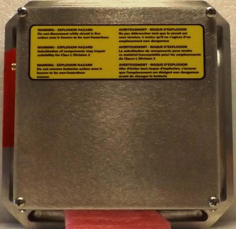
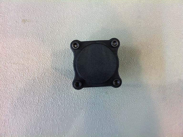
C-0101732-RA-1-1 WASP FCC/IC Exhibit Boss Pac Revision #: 0 External Photographs C-0101732-RA-1-1 WASP FCC/IC Exhibit Boss Pac Revision #: 0
Confidentiality Statement: This report and the information contained herein represent the results of testing articles/products identified and selected by the client. The tests were performed to specifications and/or procedures approved by the client. National Technical Systems (“NTS”) makes no representations expressed or implied that such testing fully demonstrates efficiency, performance, reliability, or any other characteristic of the articles being tested, or similar products. This report should not be relied upon as an endorsement or certification by NTS of the equipment tested, nor does it represent any statement whatsoever as to its merchantability or fitness of the test article or similar products for a particular purpose. This document shall not be reproduced except in full without written approval from National Technical Systems (“NTS”) and the customer. Certification Test Report BossPac Engineering & Technology WASP FCC ID: ZI8EA160 IC: 9648A-EA160 Project Code C-0101732 (Report C-0101732-RA-1-1) Revision: 1 (This report supersedes CG-1084-RA-1-0) May 2, 2011 Prepared for: BossPac Engineering & Technology Author: Deniz Demirci Senior Wireless / EMC Technologist Approved by: Nick Kobrosly Director of Canadian Operations C-0101732-RA-1-1 WASP Compliance Test Report BossPac FCC ID: ZI8EA160 IC: 9648A-EA160 _____________________________________________________________________ The test results contained in this report refer exclusively to the product(s) presented for testing. The test results do not cover models or products not referred herein. This test report should not be published or duplicated in whole or part without permission from the testing body and the customer. NTS Product Integrity Laboratory, 5151-47 th Street N.E. Tel: 403-568-6605, Fax: 403-568-6970 Confidential Page 2 of 29 May 2, 2011 Report Summary Test Facility: National Technical Systems, Canada Product Integrity Laboratory 5151-47 th Street, N.E. Calgary Alberta T3J 3R2 Accreditation Numbers: FCC 101386 IC 3978A-1 Accredited by A2LA, The American Association for Laboratory Accreditation Conforms with requirements of ISO/IEC 17025 0214.22 Electrical 0214.23 Mechanical CLIENTS SERVED: All interested parties FIELDS OF TESTING: Electrical/Electronic, Mechanical/Physical ACCREDITATION DATE: May 14, 2009 VALID TO: December 31, 2011 Applicant: BossPac Engineering & Technology Bay 8, 1450 - 28 Ave NE Calgary, AB T2A 7W6 Canada Customer Representative: Name: Anthony Bastiaansen Phone #: 403) 216-1226 Email Address: [email protected] C-0101732-RA-1-1 WASP Compliance Test Report BossPac FCC ID: ZI8EA160 IC: 9648A-EA160 _____________________________________________________________________ The test results contained in this report refer exclusively to the product(s) presented for testing. The test results do not cover models or products not referred herein. This test report should not be published or duplicated in whole or part without permission from the testing body and the customer. NTS Product Integrity Laboratory, 5151-47 th Street N.E. Tel: 403-568-6605, Fax: 403-568-6970 Confidential Page 3 of 29 May 2, 2011 Test Summary Appendix Test/Requirement Description Deviations from: Pass / Fail Applicable FCC Rule Parts Applicable Industry Canada Rule Parts Base Standard Test Basis NTS Procedure A 20 dB Bandwidth No No No Pass FCC Subpart C 15.215 NA B Occupied Bandwidth (99% emission bandwidth) No No No N/A N/A RSS-Gen Issue 3 4.6.1 C Field Strength of Fundamental No No No Pass FCC Subpart C 15.249 (a) RSS 210 Issue 8 A2.9 (a) D Radiated Spurious Emissions Band Edge No No No Pass FCC Subpart C 15.249, 15.205 RSS 210 Issue 8 A2.9 E Radiated Spurious Emissions (Tx) No No No Pass FCC Subpart C 15.249, 15.205 RSS 210 Issue 8 2.5, A2.9 F Radiated Spurious Emissions (Un-intentional radiators) No No No Pass FCC Subpart B 15.109 ICES-003 Issue 4 Test Result: The product presented for testing complied with test requirements as shown above. Prepared By: _____________________ Deniz Demirci Senior Wireless/EMC Technologist Reviewed By: ______________________ Approved By: ______________________ Glen Moore Alex Mathews Wireless/EMC Manager Quality Management Representative C-0101732-RA-1-1 WASP Compliance Test Report BossPac FCC ID: ZI8EA160 IC: 9648A-EA160 _____________________________________________________________________ The test results contained in this report refer exclusively to the product(s) presented for testing. The test results do not cover models or products not referred herein. This test report should not be published or duplicated in whole or part without permission from the testing body and the customer. NTS Product Integrity Laboratory, 5151-47 th Street N.E. Tel: 403-568-6605, Fax: 403-568-6970 Confidential Page 4 of 29 May 2, 2011 Table of Contents REPORT SUMMARY ....................................................................................................................................... 2 TEST SUMMARY ............................................................................................................................................. 3 REGISTER OF REVISIONS ............................................................................................................................ 5 1.0 INTRODUCTION ................................................................................................................................. 6 1.1 P URPOSE .............................................................................................................................................. 6 2.0 EUT DESCRIPTION ........................................................................................................................... 6 2.1 C ONFIGURATION .................................................................................................................................... 6 2.2 EUT CABLES ..............................................................................................................…
Text truncated - open the document above for the full version.
C-0101732-RA-1-1 WASP FCC/IC Exhibit Boss Pac Date: May 2, 2011 Revision #: 0 Test Setup Photographs Radiated Emission setup Radiated Emission (Upright position) C-0101732-RA-1-1 WASP FCC/IC Exhibit Boss Pac Date: May 2, 2011 Revision #: 0 Radiated Emission (On Edge position) Radiated Emission (Flat position)
| # | Rule Parts | Frequency Range | Power Output |
|---|---|---|---|
| 1 | 15C | 2.40 GHz - 2.48 GHz | - |

Digital Transceiver Module
Equipment Class
DTS - Digital Transmission System