FCCID.CO- FCC ID Database
HomeCompaniesEquipment ClassesSearch

© 2026 FCC ID Database. All rights reserved.

AboutContactData sourced from FCC public records
  1. Home/
  2. BossPac Engineering & Technology Inc/
  3. ZI8EA206

ZI8EA206Digital Transceiver Module

BossPac Engineering & Technology Inc
Digital Transceiver Module - FCC ID ZI8EA206 - BossPac Engineering & Technology Inc
Click to zoom

Application Details

Equipment Class
DTS - Digital Transmission System
Date of Grant
Jul 22, 2021
Application Purpose
Original Equipment
Date of Application
Jul 22, 2021
Equipment Note
Digital Transceiver Module
Frequency Range
906.00000000 - 924.00000000
Company
BossPac Engineering & Technology Inc
Country
Canada

Documents & Files

Select a file to view

Users Manual

↗
↗
↗

Cover Letter(s)

↗
↗
↗
↗

External Photos

↗
↗
↗
↗

ID Label/Location Info

↗
↗
↗

Internal Photos

↗

RF Exposure Info

↗

Test Report

↗

Test Setup Photos

↗

Document Text

Text extracted from the exhibit documents filed with the FCC. Open a document above to read the original.

Users Manual

EA000405 – BOARDER ROUTER 1 EA000405 Border Router INSTRUCTION MANUAL VERSION 1.0 EA000405 – BOARDER ROUTER 2 VISIT OUR WEBSITE FOR MORE INFORMATION. WWW.BOSSPAC.COM BOSSPAC ENGINEERING TECHNOLOGY, CALGARY HEAD OFFICE PHONE: (403) 216-1226 FAX: (403) 216-5557 E-MAIL: [email protected] 1450 – 28 STREET NE BAY 8, CALGARY, ALBERTA, CANADA T2A 7W6 EA000405 – BOARDER ROUTER 3 Introduction This manual provides basic information on how to commission or join a border router to any device:  Commission a Border Router onto an existing network  Joining a Border Router onto a network Required Tools:  Computer (Run on Windows)  EA000405 Border Router  10 to 24V Power Supply  915 MHz Antenna  Ethernet Cable o Physical connection to Personal Internet router. 915 MHz Antenna DRC Gateway 12V Power Supply Ethernet cable EA000405 – BOARDER ROUTER 4 1. Commission/Joining Border Router to a network 1 Installation The EA000405 Border Router must be installed by a professional or certified technician conversant with the certification requirements of the installation site. The EA000405 Border Router requires a voltage between 10 VDC and 24 VDC capable of supplying up to 2A. Unless otherwise specified the EA000405 Border Router ships with a 3 dBi antenna (EA002058). The EA000405 Border Router is compatible with the following antennas. BossPac PN Gain EH002058 (Standard) 3 dBi EH002059 1.2 dBi EH002060 8 dBi EH000625 11 dBi 2 Commissioning 2.1 Set-up & Power On - Connect one end of the Ethernet cable to your ethernet router. - Connect the other end of the Ethernet cable to the border router (Figure 1) Figure 1 - Connect the Power Supply corresponding wires to Border Router power port (Figure 2) EA000405 – BOARDER ROUTER 5 Figure 2 - Connect to the 915 MHz Antenna to Border Router (Figure 3) Figure 3 - Power on/ Plug in the power Supply 2.2 SSH to Border Router - On your laptop open Command prompt - On command prompt type “ssh pi@###.###.##.##” “#” = Border Router IP address - If connecting to the border router for the first time, command prompt will print “Are you sure you want to continue connecting (yes/no)?” - Type on command prompt “yes” - If the border has a password, command prompt will ask you for a password in which then you type password and then press enter. - Command prompt will print “pi@###.###.##.##:~ $” EA000405 – BOARDER ROUTER 6 2.3 Joining, Commissioning and Starting a Network 2.3.1 Joining Ethernet Gateway to an existing network: - On command prompt type “sudo ot-ctl” then press enter - Command prompt will print “>” - On command prompt type “ifconfig up” then press enter - Command prompt will print “up” - On command prompt type “joiner start 123456” then press enter’ - Command prompt will print “Done”, and if joining with the device is successful, command prompt will print “joiner successful” - On command prompt type “thread start” then press enter - Command prompt will print “Done” 2.3.2 Commission a device to the network - On command prompt type “sudo ot-ctl” then press enter - Command prompt will print “>” - On command prompt type “Commissioner start” then press enter - Command prompt will print “Done” and “> Commissioner: active” - On command prompt type “commissioner joiner add * 123456” then press enter - Command prompt will print “Done” - To close commissioner type on command prompt “commissioner stop” then press enter - Command prompt will print “Commissioner: disabled” and “Done” 2.3.3 Start a Network - On command prompt type “sudo ot-ctl” then press enter - Command prompt will print “>” - On command prompt type “dataset init new” then press enter - Command prompt will print “Done” - On command prompt type “dataset channel x”; where x represents the desired channel. Valid numbers are between 1 and 10. then press enter - Command prompt will print “Done” - Type “dataset commit active” - Command prompt will print “Done” - Type “ifconfig up” - Type “thread start” - EA000405 – BOARDER ROUTER 7 FCC & IC Statements FCC Class B Part 15 This device complies with part 15 of the FCC Rules. Operation is subject to the following two conditions: (1) This device may not cause harmful interference, and (2) this device must accept any interference received, including interference that may cause undesired operation. Changes or modifications not expressly approved by BossPac Engineering Technology Inc. may void the user’s authority to operate the equipment. ISED RSP-100 Statement This device complies with Industry Canada license-exempt RSS standard(s). Operation is subject to the following two conditions: (1) this device may not cause interference, and (2) this device must accept any interference, including interference that may cause undesired operation of the device. Le présent appareil est conforme aux CNR d'Industrie Canada applicables aux appareils radio exempts de licence. L'exploitation est autorisée aux deux conditions suivantes : (1) l'appareil ne doit pas produire de brouillage, et (2) l'utilisateur de l'appareil doit accepter tout brouillage radioélectrique subi, même si le brouillage est susceptible d'en compromettre le fonctionnement. FCC/IC RF Exposure Statement This equipment complies with FCC radiation exposure limits set forth for an uncontrolled environment. The antenna(s) used for this equipment must be installed to provide a separation distance of at least 8 inches (20cm) from all persons. Cet équipement est conforme à l'exposition aux radiations de FCC et d'Industrie Canada établies pour un environnement non contrôlé. L'antenne (s) utilisé pour cet équipement doit être installé pour fournir une distance d'au moins 20cm à partir de toutes les personnes. EA000405 – BOARDER ROUTER 8 For further Technical Assistance Email [email protected] Or call (866) 616-1226 or (403) 216-1226

Users Manual

BossPac WASP™ NEST3 SMART RECEIVER AND GATEWAY USER MANUAL VERSION 1.0 WASP™ is a registered trademark owned by BossPac Engineering & Technology WASP™ is a PATENT PENDING technology owned by BossPac Engineering & Technology BossPac Engineering & Technology 1450 – 28 Street NE Bay 8, Calgary, Alberta, Canada T2A 7W6 Phone: (403) 216-1226 Fax: (403) 216-5557 E-Mail: [email protected] Visit our website for more information www.bosspac.com WASP™ NEST3 Smart Receiver and Gateway Operations Manual - 1 - WARNING READ THIS MANUAL BEFORE OPERATING THIS DEVICE. MISE EN GARDE LISEZ LE MANUEL AVANT UTILISATER WARNING TO PREVENT EQUIPMENT FAILURE, AND/OR DAMAGE, AND/OR PERSONAL INJURY, REGULAR CALIBRATION AND INSPECTION OF THIS DEVICE IS REQUIRED. MISE EN GARDE POUR PRЀVENIR LE DOMMAGE À L’EQUIPMENT, ET/AU AUX PERSON, LA CÀLIBRATION ET L’INSPECTION REGULIER EST ŔEQUIS. WASP™ NEST3 Smart Receiver and Gateway Operations Manual - 2 - WARNING - EXPLOSION HAZARD SUBSTITUTION OF COMPONENTS MAY IMPAIR SUITABILITY FOR CLASS 1, DIVISION 2. AVERTISSEMENT – RISQUE D’EXPLOSION LA SUBSTITUTION DECOMPOSANTS RENDRE CE MATÉRIEL INACCEPTABLE POUR LES EMPLACEMENTS DE CLASSE 1, DIVISION 2 WARNING - EXPLOSION HAZARD DO NOT RECONNECT POWER IN A HAZARDOUS ENVIRONMENT. AVERTISSEMENT - RISQUE D’EXPLOSION NE PAS BRANCHEZ LA PRISE DANS UN ENVIRONMENT FLAMMABLE. WASP™ NEST3 Smart Receiver and Gateway Operations Manual - 3 - Table of Contents 1. Introduction ......................................................................................................................... 5 1.1 NEST Receiver Introduction ............................................................................................ 5 2. Installation ........................................................................................................................... 5 2.1 Included In The Package ................................................................................................. 5 2.2 Installation ........................................................................................................................ 5 2.2.1 Nest Receiver Installation .......................................................................................... 5 2.3 Wiring NEST Receiver ..................................................................................................... 5 2.3.1 Nest Receiver Mounting ............................................................................................ 5 2.3.2 Attaching the Antenna ............................................................................................... 5 2.3.3 Attaching the LTE Antenna ........................................................................................ 6 2.3.3 Wiring NEST Circuit Board ......................................................................................... 6 2.3.4 Circuit Board Terminal Block ..................................................................................... 6 3. Interface ............................................................................................................................ 7 3.1 System Status Screens ................................................................................................... 8 3.2 Main Menu ....................................................................................................................... 9 3.2.1 System Info ................................................................................................................... 9 3.2.1.1 Version ................................................................................................................... 9 3.2.1.2 Uptime ................................................................................................................... 9 3.2.1.3 Radio ..................................................................................................................... 9 3.2.2 System Settings ...........................................................................................................10 3.2.2.1 SET LOG OPTION .................................................................................................10 3.2.2.2 Set Time/Date .......................................................................................................11 3.2.2.3 Set Password ........................................................................................................11 3.2.2.4 Set Modbus Parameter .........................................................................................11 3.2.2.5 Set Temperature Unit ............................................................................................12 3.2.2.6 Set Velocity Units ..................................................................................................13 3.2.2.7 Set Pressure Units ................................................................................................14 3.2.2.8 Set Level Units ......................................................................................................14 3.2.2.9 Clearing All Sensors ..............................................................................................14 3.2.2.10 Adjust Brightness ................................................................................................14 3.2.2.11 Reset System Settings ........................................................................................15 3.2.3 LOGS ..........................................................................................................................15 3.2.3.1 Connecting to the USB port ....................................................................................15 WASP™ NEST3 Smart Receiver and Gateway Operations Manual - 4 - 3.2.3.2 Retrieving the Logs ................................................................................................15 3.2.3.3 Formatting the microSD Card .................................................................................15 3.…

Text truncated - open the document above for the full version.

Users Manual

Model EA000144 NEST Receiver USER MANUAL VERSION 1.00 BossPac Engineering & Technology 1450 – 28 Street NE Bay 8, Calgary, Alberta, Canada T2A 7W6 Phone: (403) 216-1226 / Fax: (403) 216-5557 / E-Mail: [email protected] Visit our website for more information www.bosspac.com EA000144 User Manual Page 3 WARNING READ THIS MANUAL BEFORE OPERATING THIS DEVICE. MISE EN GARDE LISEZ LE MANUEL AVANT D’UTILISER CET APPAREIL. WARNING TO PREVENT EQUIPMENT FAILURE, AND/OR DAMAGE, AND/OR PERSONAL INJURY, REGULAR CALIBRATION AND INSPECTION OF THIS DEVICE IS REQUIRED. MISE EN GARDE POUR PREVENIR L’ENDOMMAGEMENT DE L’EQUIPMENT, ET/OU AUX PERSONNES, LA CALIBRATION ET L’INSPECTION REGULIERE DE CET APPAREIL SONT REQUISES. EA000144 User Manual Page 4 WARNING: OPERATING TEMPERATURE NEST UNIT IS DESIGNED TO WORK BETWEEN -40C AND +80C. MISE EN GARDE : TEMPERATURE DE FONCTIONNEMENT L’UNITE NEST EST CONCUE POUR FONCTIONNER ENTRE -40C ET +80C. EA000144 User Manual Page 5 Table of Contents 1. Introduction ......................................................................................................................... 6 1.1. NEST System overview ............................................................................................... 6 1.2. Included Contents ........................................................................................................ 6 1.3. NEST Receiver ............................................................................................................ 7 2. Installation ........................................................................................................................... 8 2.1. NEST Installation ......................................................................................................... 8 2.2. NEST Receiver Mounting ............................................................................................. 8 2.3. Attaching the 915 MHz Antenna ................................................................................... 8 2.4. Attaching the LTE Antenna .......................................................................................... 8 2.5. Wiring .......................................................................................................................... 9 3. Interface .............................................................................................................................. 9 3.1. STATUS SCREEN (Default Screen) ...........................................................................10 3.1.1. Network status .....................................................................................................10 3.2. System Menu ..............................................................................................................11 3.3. System Info .................................................................................................................11 3.4. Network Settings .........................................................................................................11 3.4.1. Factory RESET ....................................................................................................11 3.4.2. Join Network ...........................................................................................................12 3.4.3. Select Server ...........................................................................................................12 3.5. Set Time / Date ...........................................................................................................12 3.6. Send Test Message ....................................................................................................13 3.7. Device Menu ...............................................................................................................13 3.8. Set Scan Interval ........................................................................................................14 4. Maintenance ......................................................................................................................15 4.1. Rear Cover .................................................................................................................15 4.2. Replacing Batteries .....................................................................................................15 4.3. RTC coin battery .........................................................................................................15 5. Contact Info .......................................................................................................................16 EA000144 User Manual Page 6 1. Introduction 1.1. NEST System overview The NEST is a wireless communication system designed to transmit data from fixed, mobile and quick deploy sensors to a server. The NEST Receiver is compatible with 915 MHz BossPac wireless sensors bearing the BossPac WASP™ logo. This Operations Manual provides basic information on how to install and operate the NEST System. 1.2. Included Contents  1x EA000144 - NEST Receiver  1x 3 dBi 915MHz antenna.  8’ SMA to N-Type cable for 915 MHz antenna  1x LTE Antenna EA000144 User Manual Page 7 1.3. NEST Receiver EA000144 User Manual Page 8 2. Installation 2.1. NEST Installation The equipment should be installed by a professional or certified technician conversant with the certification requirements of the installation site. 2.2. NEST Receiver Mounting The BossPac NEST™ receiver may be installed into an existing panel or an enclosure. Ideal location would have direct line of sight to the sensors. There are four mounting locations (threaded holes) and an environmental gasket on the flange of the receiver. A cutout mounting template is also included with the receiver. 2.3. Attaching the 915 MHz Antenna A 915 MHz antenna is provided by BossPac, included and shipped with the NEST Receiver. The NEST Receiver is certified for use with the following models: BossPac PN Gain EH002058 (Standard) 3 dBi …

Text truncated - open the document above for the full version.

Cover Letter(s)

_____________________________________________________________________________________ BossPac Engineering & Technology 1450 28 th Street NE, Bay 8, Calgary, Alberta, CANADA, T2A 7W6 Toll Free 866-616-1226 www.bosspac.com Date: 23 May, 2021 To: Federal Communications Commission Authorization and Evaluation Division 7435 Oakland Mills Rd. Columbia, MD 21046 RE: Limited Modular Approval Attestation of FCC ID: ZI8EA206 This is a request for a Limited Modular Approval of FCC ID: ZI8EA206 in accordance with 47 CFR 15.212(b). The following is a declaration of conditions. A ✔ denotes compliance to the applicable rule part. §15.212 Modular transmitters. (a) Single modular transmitters consist of a completely self-contained radiofrequency transmitter device that is typically incorporated into another product, host or device. Split modular transmitters consist of two components: a radio front end with antenna (or radio devices) and a transmitter control element (or specific hardware on which the software that controls the radio operation resides). All single or split modular transmitters are approved with an antenna. All of the following requirements apply, except as provided in paragraph (b) of this section. (1) Single modular transmitters must meet the following requirements to obtain a modular transmitter approval. ✔ (i) The radio elements of the modular transmitter must have their own shielding. The physical crystal and tuning capacitors may be located external to the shielded radio elements. ✔ (ii) The modular transmitter must have buffered modulation/data inputs (if such inputs are provided) to ensure that the module will comply with part 15 requirements under conditions of excessive data rates or over-modulation. (iii) The modular transmitter must have its own power supply regulation. ✔ (iv) The modular transmitter must comply with the antenna and transmission system requirements of §§15.203, 15.204(b) and 15.204(c). The antenna must either be permanently attached or employ a “unique” antenna coupler (at all connections between the module and the antenna, including the cable). The “professional installation” provision of §15.203 is not applicable to modules but can apply to limited modular approvals under paragraph (b) of this section. (v) The modular transmitter must be tested in a stand-alone configuration, i.e., the module must not be inside another device during testing for compliance with part 15 requirements. Unless the transmitter module will be battery powered, it must comply with the AC line conducted requirements found in §15.207. AC or DC power lines and data input/output lines connected to the module must not contain ferrites, unless they will be marketed with the module (see §15.27(a)). The length of these lines shall be the length typical of actual use or, if that length is unknown, at least 10 centimeters to insure that there is no coupling between the case of the module and supporting equipment. Any accessories, peripherals, or support equipment connected to the module during testing shall be unmodified and commercially available (see §15.31(i)). ✔ (vi) The modular transmitter must be equipped with either a permanently affixed label or must be capable of electronically displaying its FCC identification number. _____________________________________________________________________________________ BossPac Engineering & Technology 1450 28 th Street NE, Bay 8, Calgary, Alberta, CANADA, T2A 7W6 Toll Free 866-616-1226 www.bosspac.com (A) Manufacturers must ensure that only transmitter control elements and radio front end components that have been approved together are capable of operating together. The transmitter module must not operate unless it has verified that the installed transmitter control elements and radio front end have been authorized together. Manufacturers may use means including, but not limited to, coding in hardware and electronic signatures in software to meet these requirements, and must describe the methods in their application for equipment authorization. (B) If the modular transmitter uses an electronic display of the FCC identification number, the information must be readily accessible and visible on the modular transmitter or on the device in which it is installed. If the module is installed inside another device, then the outside of the device into which the module is installed must display a label referring to the enclosed module. This exterior label can use wording such as the following: “Contains FCC certified transmitter module(s).” Any similar wording that expresses the same meaning may be used. The user manual must include instructions on how to access the electronic display. A copy of these instructions must be included in the application for equipment authorization. ✔ (vii) The modular transmitter must comply with any specific rules or operating requirements that ordinarily apply to a complete transmitter and the manufacturer must provide adequate instructions along with the module to explain any such requirements. A copy of these instructions must be included in the application for equipment authorization. ✔ viii) The modular transmitter must comply with any applicable RF exposure requirements in its final configuration. (iv) Manufacturers must ensure that only transmitter control elements and radio front end components that have been approved together are capable of operating together. The transmitter module must not operate unless it has verified that the installed transmitter control elements and radio front end have been authorized together. Manufacturers may use means including, but not limited to, coding in hardware and electronic signatures in software to meet these requirements, and must describe the methods in their application for equipment authorization. (2) Split modular transmitters must meet the requirements in paragraph (a)(1) of this section, excluding paragraphs (a)(1)(i) and (a)(1)(v), and the following additional requirements to …

Text truncated - open the document above for the full version.

Cover Letter(s)

_____________________________________________________________________________________ BossPac Engineering & Technology 1450 28 th Street NE, Bay 8, Calgary, Alberta, CANADA, T2A 7W6 Toll Free 866-616-1226 www.bosspac.com Date: May 23, 2021 To: Federal Communications Commission 7435 Oakland Mills Road Columbia, Maryland 21046 USA RE: Confidentiality Request regarding application for certification of FCC ID: ZI8EA206 Pursuant to Sections 0.457 and 0.459 of the Commission’s Rules, we hereby request confidential treatment of information accompanying this application as outlined below: Exhibit Type File Name Block Diagram Exhibit 16 – Block Diagram.pdf Operation Description Exhibit 17 – Operation Description.pdf Schematic Diagram Exhibit 18 – Schematic Diagram.pdf Parts List Exhibit 19 – Bill of Material.pdf Tune-Up Procedure Exhibit 20 – Tune-Up Procedure.pdf The above materials contain trade secrets and proprietary information not customarily released to the public. The public disclosure of these materials may be harmful to the applicant and provide unjustified benefits to its competitors. The applicant understands that pursuant to Section 0.457 of the Rules, disclosure of this application and all accompanying documentation will not be made before the date of the Grant for this application. Pursuant to DA04-1705 June 15, 2004 of the Commission’s public notice, we also request temporary confidential treatment of information accompanying this application as outlined below for 180 days: Exhibit Type File Name User’s Manual Exhibit 21 – User’s Manual.pdf External Module Photos Exhibit 22 – Photos – Module External.pdf Host Internal Photos Exhibit 23 – Photos – Host Internal.pdf Host External Photos Exhibit 24 – Photos – Host External Test Setup Photos Exhibit 25 – Photos - Setup.pdf Sincerely,

Cover Letter(s)

_____________________________________________________________________________________ BossPac Engineering & Technology 1450 28 th Street NE, Bay 8, Calgary, Alberta, CANADA, T2A 7W6 Toll Free 866-616-1226 www.bosspac.com Date: 23 May 2021 To: Federal Communications Commission 7435 Oakland Mills Road Columbia, Maryland 21046 USA RE: Limited Modular Approval FCC ID: ZI8EA206 We, BossPac Engineering and Technology Inc. (BossPac), are applying for a Limited Modular Approval, FCC ID: ZI8EA206 in accordance with 47 CFR 15.212(b). Limited Modular Approval applies since the device does not have its own power supply regulation and cannot be tested in a stand-alone mode. The module is only to be integrated into host products manufactured by BossPac and will not be made publicly available to third party integrators. The host products will not be made publicly available and are to be Professionally installed. BossPac plans to integrate the EA206 module into the following hosts. NEST2, NEST3, DRC-Gateway Additional host information accompanies this application. Thank you for your consideration. Sincerely,

Cover Letter(s)

_____________________________________________________________________________________ BossPac Engineering & Technology 1450 28 th Street NE, Bay 8, Calgary, Alberta, CANADA, T2A 7W6 Toll Free 866-616-1226 www.bosspac.com Federal Communications Commission Authorization and Evaluation Division 1435 Oakland Mills Road Columbia, MD 21046 Date: 21 November 2018 SUBJECT: Letter of Authorization To Whom It May Concern: We, BossPac Engineering and Technology Inc., hereby authorize Ben Hewson or Art Voss at Celltech Labs on our behalf, to apply to the Federal Communications Commission on our equipment. Any and all acts carried out by Celltech Labs on our behalf shall have the same effect as acts of our own. This is to advise that we are in full compliance with the Anti- Drug Abuse Act. We, the applicant, are not subject to a denial of federal benefits pursuant to Section 5301 of the Anti-Drug Act of 1988, 21 USC853a, and no party to the application is subject to a denial of federal benefits pursuant to that section. Regards, _______________________________ Anthony Bastiaansen

External Photos

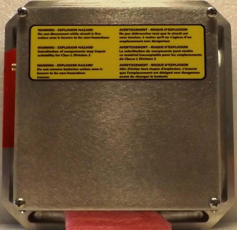
Applicant: Bosspac Engineering and Technology FCC ID: Z18EA206 Test Report S/N: 45461619-R1.0 ISED ID 9648A-EA206 ©2021 Celltech Labs Inc. This document is not to be reproduced in whole or in part without the expressed written permission of Celltech Labs Inc. Page 20 of 41 EXHIBIT 24C – PHOTOS – HOST EXTERNAL – EA000405 Figure E24C.1 – External Applicant: Bosspac Engineering and Technology FCC ID: Z18EA206 Test Report S/N: 45461619-R1.0 ISED ID 9648A-EA206 ©2021 Celltech Labs Inc. This document is not to be reproduced in whole or in part without the expressed written permission of Celltech Labs Inc. Page 21 of 41 Figure E24C.2 – External – Top / Front Applicant: Bosspac Engineering and Technology FCC ID: Z18EA206 Test Report S/N: 45461619-R1.0 ISED ID 9648A-EA206 ©2021 Celltech Labs Inc. This document is not to be reproduced in whole or in part without the expressed written permission of Celltech Labs Inc. Page 22 of 41 Figure E24C.3 – External – Top / Back Applicant: Bosspac Engineering and Technology FCC ID: Z18EA206 Test Report S/N: 45461619-R1.0 ISED ID 9648A-EA206 ©2021 Celltech Labs Inc. This document is not to be reproduced in whole or in part without the expressed written permission of Celltech Labs Inc. Page 23 of 41 Figure E24C.3 – External – Bottom

External Photos

Applicant: Bosspac Engineering and Technology FCC ID: Z18EA206 Test Report S/N: 45461619-R1.0 ISED ID 9648A-EA206 ©2021 Celltech Labs Inc. This document is not to be reproduced in whole or in part without the expressed written permission of Celltech Labs Inc. Page 15 of 41 EXHIBIT 24B – PHOTOS – HOST EXTERNAL – EA000244 NOTE: The EA000144 and EA000244 are identical in form factor. Figure E24B.1 – External Applicant: Bosspac Engineering and Technology FCC ID: Z18EA206 Test Report S/N: 45461619-R1.0 ISED ID 9648A-EA206 ©2021 Celltech Labs Inc. This document is not to be reproduced in whole or in part without the expressed written permission of Celltech Labs Inc. Page 16 of 41 Figure E24B.2 – External, Front Applicant: Bosspac Engineering and Technology FCC ID: Z18EA206 Test Report S/N: 45461619-R1.0 ISED ID 9648A-EA206 ©2021 Celltech Labs Inc. This document is not to be reproduced in whole or in part with…

Text truncated - open the document above for the full version.

Contact Information

Applicant

Anthony Bastiaansen
[email protected]403-216-1226Fax: 403-216-5557

Test Firm

CELLTECH LABS INC.Ben Hewson
[email protected]250-765-7650Fax: 250-765-7645

Technical Specifications

#Rule PartsFrequency RangePower Output
115C906 MHz - 924 MHz53.00 mW
Modular Type
Limited Single Modular Approval
Confidentiality
Long Term
Grant Notes
Limited Single Modular Approval. Limited to the following BOSSPAC host devices, NEST2, NEST3, and DRC-Gateway. Output power listed is the maximum conducted output power. This device is to be used only for mobile and fixed applications. The module antenna(s) must be installed to meet the RF exposure compliance separation distance of 20 cm and any additional testing and authorization process as required. Co-location of this module with other transmitters that operate simultaneously are required to be evaluated using the FCC multi-transmitter procedures. End-Users must be provided with transmitter operating conditions for satisfying RF exposure compliance. Separate approval is required for all other operating configurations, including portable configurations with respect to 2.1093 and different antenna configurations.
Other Applications from BossPac Engineering & Technology Inc

WASP - FCC ID ZI8EA160 - BossPac Engineering & Technology Inc
ZI8EA160

WASP

Jul 31, 2011

Equipment Class

DXX - Part 15 Low Power Communication Device Transmitter