ZIMH30MAmbulatory electrocardiograph monitor with onboard ECG analysis and wireless connection via Wi-Fi and BLE
TZ MEDICAL INC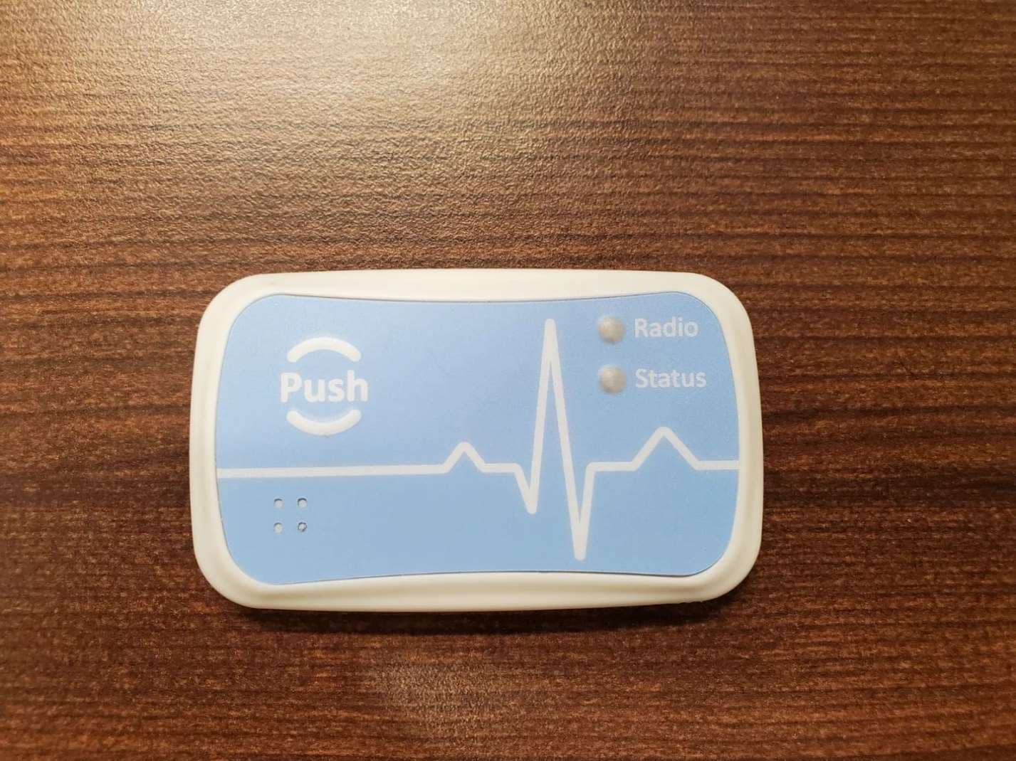
Click to zoom
Application Details
- Equipment Class
- DTS - Digital Transmission System
- Date of Grant
- Jun 17, 2026
- Application Purpose
- Original Equipment
- Equipment Note
- Ambulatory electrocardiograph monitor with onboard ECG analysis and wireless connection via Wi-Fi and BLE
- Frequency Range
- 2402.00000000 - 2480.00000000
- Company
- TZ MEDICAL INC
- Country
- United States
Documents & Files
Document Text
Text extracted from the exhibit documents filed with the FCC. Open a document above to read the original.
Users Manual
Revision 1.6 Document No. 23899 Page 1 Trident ® 30M Mobile Patch Monitor Operator Manual Revision 1.6 Document No. 23899 Page 2 Contents Device Overview ........................................................................................................................................................4 Description .......................................................................................................................................................................... 4 Indications for Use .............................................................................................................................................................. 5 Contraindications ................................................................................................................................................................ 6 Recorder Components ........................................................................................................................................................ 7 Equipment Symbols ............................................................................................................................................................ 8 Precautions ....................................................................................................................................................................... 10 Prepare Device ........................................................................................................................................................ 11 Format and Configure ....................................................................................................................................................... 11 Check Battery Status ......................................................................................................................................................... 13 Wireless Connections ............................................................................................................................................... 14 Connecting to BLE ............................................................................................................................................................. 14 Electrode Patch Application ..................................................................................................................................... 16 Preparing the Area ............................................................................................................................................................ 16 Starting a Study ................................................................................................................................................................. 17 During a Study ................................................................................................................................................................... 19 Extended Studies............................................................................................................................................................... 20 Ending a Study ................................................................................................................................................................... 21 3-Lead Cable Application .......................................................................................................................................... 22 Preparing the Area ............................................................................................................................................................ 22 Starting a Study with Lanyard ........................................................................................................................................... 22 Starting a Study with Lead Clip ......................................................................................................................................... 23 During a Study ................................................................................................................................................................... 25 Extended Studies............................................................................................................................................................... 26 Ending a Study ................................................................................................................................................................... 27 After a Study ............................................................................................................................................................ 28 Retrieving Patient Data ..................................................................................................................................................... 28 Removing Patient Data ..................................................................................................................................................... 29 Charging ............................................................................................................................................................................ 31 Patient Instructions .................................................................................................................................................. 32 Patient Use Precautions .................................................................................................................................................... 32 Patient Responsibilities ..................................................................................................................................................... 32 Maintenance ........................................................................................................................................................... 33 Cleaning ..................…
Text truncated - open the document above for the full version.
External Photos
Model: H30M External Photos Back View Front View
ID Label/Location Info
Back of Device
Internal Photos
Model: H30M Internal Photos View 1 View 2 View 3
RF Exposure Info
© 2025 RF Exposure Lab, LLC This report shall not be reproduced except in full without the written approval of RF Exposure Lab, LLC. 802 N. Twin Oaks Valley Road, Suite 105 • San Marcos, CA 92069 • U.S.A. TEL (760) 471-2100 • FAX (760) 471-2121 http://www.rfexposurelab.com CERTIFICATE OF COMPLIANCE SAR EVALUATION TZ Medical Inc. Dates of Test: September 25, 2025 20497 SW Teton Ave, Suite A Test Report Number: SAR.20250911 Tualatin, OR 97062 Revision B Lab Designation Number: US1195 This wireless mobile and/or portable device has been shown to be compliant for localized specific absorption rate (SAR) for uncontrolled environment/general exposure limits specified in ANSI/IEEE Std. C95.1-1992 and had been tested in accordance with the measurement procedures specified in KDB 447498 and KDB 248227 (See test report). I attest to the accuracy of the data. All measurements were performed by myself or were made under my supervision and are correct to the best of my knowledge and belief. I assume full responsibility for the completeness of these measurements and vouch for the qualifications of all persons taking them. RF Exposure Lab, LLC certifies that no party to this application is subject to a denial of Federal benefits that includes FCC benefits pursuant to Section 5301 of the Anti-Drug Abuse Act of 1988, 21 U.S.C. 853(a). Jay M. Moulton Vice President Testing Cert. # 2387.01 FCC ID: ZIMH30M Model: H30M Test Sample: Engineering Unit Same as Production Serial Number: Eng 1 Equipment Type: Wireless Body Worn Classification: Portable Transmitter Next to Body TX Frequency Range: 2412 – 2462 MHz Frequency Tolerance: ± 2.5 ppm Maximum RF Output: 2450 MHz (b) – 18.3 dBm, 2450 MHz (g) – 18.3 dBm, 2450 MHz (n20) – 18.3 dBm, 2450 MHz (BT) – 3.8 dBm Conducted Signal Modulation: DSSS, OFDM Antenna Type: Internal Antenna Application Type: Certification FCC Rule Parts: Part 2, 15C KDB Test Methodology: KDB 447498 D01 v06, KDB 248227 v02r02 Maximum SAR Value: 0.74 W/kg Reported Simultaneous SAR Vale: 0.84 W/kg Reported Separation Distance to Probe: 0 mm Report Number: SAR.20250911 © 2025 RF Exposure Lab, LLC Page 2 of 62 This report shall not be reproduced except in full without the written approval of RF Exposure Lab, LLC. Table of Contents 1. Introduction ................................................................................................................................................ 4 SAR Definition [5] .......................................................................................................................................... 5 2. SAR Measurement Setup .......................................................................................................................... 6 Robotic System ............................................................................................................................................. 6 System Hardware .......................................................................................................................................... 6 System Electronics ........................................................................................................................................ 7 Probe Measurement System ......................................................................................................................... 7 3. Probe and Dipole Calibration ................................................................................................................... 14 4. Phantom & Simulating Tissue Specifications ........................................................................................... 15 Head Simulating Mixture Characterization ................................................................................................... 15 5. RF Exposure Limits [2] ............................................................................................................................. 16 Uncontrolled Environment ............................................................................................................................ 16 Controlled Environment ............................................................................................................................... 16 6. Measurement Uncertainty ........................................................................................................................ 17 7. SAR System Verification .......................................................................................................................... 18 Tissue Verification ....................................................................................................................................... 18 SAR System Verification .............................................................................................................................. 18 8. SAR Test Data Summary ......................................................................................................................... 19 Procedures Used To Establish Test Signal .................................................................................................. 19 Device Test Condition .................................................................................................................................. 19 9. SAR Test Results .................................................................................................................................... 22 10. Simultaneous Transmission Analysis ................................................................................................... 24 11. Test Equipment List ............................................................................................................................. 25 12. Conclusion ........................................................................................................................................... 26 13. References ......................................................…
Text truncated - open the document above for the full version.
Test Report
A2LA Accredited IC recognized # 3462B CETECOM Inc. 411 Dixon Landing Road Milpitas, CA 95035 U.S.A. Phone: + 1 (408) 586 6200 Fax: + 1 (408) 586 6299 E-mail: [email protected] http://www.cetecom.com CETECOM Inc. is a Delaware Corporation with Corporation number: 2905571 © Copyright by CETECOM FCC / ISED Test Report For: TZ Medical Model Name: H30M Product Description: Ambulatory electrocardiograph monitor with onboard ECG analysis and wireless connection via Wi-Fi and BLE FCC ID: ZIMH30M ISED: 9647A-H30M Applied Rules and Standards: 47 CFR Part 15.247 (DTS) RSS-247 Issue 4 (DTS) & RSS-Gen Issue 5 REPORT #: EMC_TZMED_023_24001_15_247_BLE_Rev4 DATE: 2026-06-04 Test Report #: EMC_TZMED_023_24001_15247_BLE_Rev4 FCC ID:ZIMH30M Date of Report 2026-06-04 Page 2 of 55 ISED: 9647A-H30M TABLE OF CONTENTS 1ASSESSMENT .............................................................................................................................................................. 3 2ADMINISTRATIVE DATA ............................................................................................................................................... 4 2.1IDENTIFICATION OF THE TESTING LABORATORY ISSUING THE EMCTEST REPORT ........................................................................... 4 2.2IDENTIFICATION OF THE CLIENT ............................................................................................................................................. 4 2.3IDENTIFICATION OF THE MANUFACTURER ................................................................................................................................. 4 3EQUIPMENT UNDER TEST (EUT) ................................................................................................................................... 5 3.1EUTSPECIFICATIONS ......................................................................................................................................................... 5 3.2EUTSAMPLE DETAILS ......................................................................................................................................................... 6 3.3ACCESSORY EQUIPMENT (AE) DETAILS ................................................................................................................................... 6 3.4TEST SAMPLE CONFIGURATION ............................................................................................................................................. 6 3.5MODE OF OPERATION DETAILS .............................................................................................................................................. 6 3.6JUSTIFICATION FOR WORST CASE MODE OF OPERATION ............................................................................................................ 7 4SUBJECT OF INVESTIGATION ...................................................................................................................................... 8 5MEASUREMENT RESULTS SUMMARY .......................................................................................................................... 8 6MEASUREMENT UNCERTAINTY.................................................................................................................................... 9 6.1MEASUREMENT UNCERTAINTY .............................................................................................................................................. 9 6.2ENVIRONMENTAL CONDITIONS DURING TESTING: ...................................................................................................................... 9 6.3DATE OF TESTING: .............................................................................................................................................................. 9 6.4DECISION RULE: ................................................................................................................................................................. 9 7MEASUREMENT PROCEDURES .................................................................................................................................. 10 7.1RADIATED MEASUREMENT .................................................................................................................................................. 10 7.2POWER LINE CONDUCTED MEASUREMENT PROCEDURE .......................................................................................................... 13 7.3RFCONDUCTED MEASUREMENT PROCEDURE ....................................................................................................................... 13 8TEST RESULT DATA .................................................................................................................................................. 14 8.1MAXIMUM PEAK CONDUCTED OUTPUT POWER ....................................................................................................................... 14 8.2POWER SPECTRAL DENSITY ............................................................................................................................................... 17 8.3BAND EDGE COMPLIANCE .................................................................................................................................................. 20 8.4EMISSION BANDWIDTH 6DB AND 99%OCCUPIED BANDWIDTH ................................................................................................... 27 8.5RADIATED TRANSMITTER SPURIOUS EMISSIONS AND RESTRICTED BANDS ................................................................................... 33 8.6ACPOWER LINE CONDUCTED EMISSIONS ............................................................................................................................. 51 9TEST SETUP PHOTOS ................................................................................................................................................ 53 10TEST EQUIPMENT A…
Text truncated - open the document above for the full version.
Test Report
SPE-11-8-146-V 2.4GHz High Efficiency Loop Antenna Part No: WLA.01 Description 2400MHz to 2500MHz WLAN/Wi-Fi®/Bluetooth® Features: Low Profile SMD Antenna Dimensions: 3.2 x 1.6 x 0.5mm Peak gain 1dBi typ 50Ω Impedance RoHS and REACH Compliant 2 www.taoglas.com SPE-11-8-146-V 1. Introduction 3 2. Specification 4 3. Mechanical Drawing 6 4. Antenna Integration Guide 7 5. Solder Reflow Profile 15 6. Packaging 16 7. Antenna Characteristics 17 8. Radiation Patterns 21 9. Application Note 25 Changelog 37 Taoglas makes no warranties based on the accuracy or completeness of the contents of this document and reserves the right to make changes to specifications and product descriptions at any time without notice. Taoglas reserves all rights to this document and the information contained herein. Reproduction, use or disclosure to third parties without express permission is strictly prohibited. 3 www.taoglas.com SPE-11-8-146-V 1. Introduction The WLA.01 2.4GHz Loop antenna is a high efficiency, miniature SMD, edge mounted ceramic antenna for very small space requirements for Wi-Fi®, WLAN, Zigbee®, Bluetooth®, and 802.11 applications. At just 3.2mm*1.6mm*0.5mm, the WLA.01 is one of the smallest antennas available worldwide. The WLA.01 uses the main PCB as its ground plane, thereby increasing the efficiency of the antenna. It can be tuned for different PCB sizes, simply by changing the value of the matching circuit. The antenna can be mounted either at the centre or the corner of the PCB, see section 4 for integration guidelines. This antenna is delivered on tape and reel for ease of assembly in production. Upon testing of any of our antennas with your device and a selection of appropriate layout, integration technique, or cable, Taoglas can make sure any of our antennas’ peak gain will be below the peak gain limits. Taoglas can then issue a specification and/or report for the selected antenna in your device that will clearly show it complying with the peak gain limits, so you can be assured you are meeting regulatory requirements for that module. For example, a module manufacturer may state that the antenna must have less than 2dBi peak gain, but you don’t need to select an embedded antenna that has a peak gain of less than 2dBi in free-space. This will give you a less optimized solution. It is better to go for a slightly higher free-space peak gain of 3dBi or more if available. Once that antenna gets integrated into your device, performance will degrade below this 2dBi peak gain due to the effects of GND plane, surrounding components, and device housing. If you want to be absolutely sure, contact Taoglas and we will test. Choosing a Taoglas antenna with a higher peak gain than what is specified by the module manufacturer and enlisting our help will ensure you are getting the best performance possible without exceeding the peak gain limits. This antenna can be mounted with no performance degradation in either orientation if the antenna is soldered correctly via Surface mounting. Please see the integration instructions section for further detail regarding the optimum way to integrate this antenna into your device. 4 www.taoglas.com SPE-11-8-146-V The WLA.01 is designed to mount at the center of the edge of an evaluation board measuring 80 x 40mm. The antenna performance was measured with the WLA.01 mounted on the evaluation board with SMA(F) connector. Typical Applications Include: • Bluetooth® Devices such as Headphones • Hand-held devices when Bluetooth®/Wi-Fi® functions are needed, e.g., Smart phone. • Devices requiring IEEE802.11 b/g and ZigBee® • Wireless PCMCIA cards or USB dongle For further optimization to customer-specific device environments and for support to integrate and test this antennas performance in your device, contact your regional Taoglas Customer Services Team. 5 www.taoglas.com SPE-11-8-146-V 2. Specification Wi-Fi Electrical Band Frequency (MHz) Efficiency (%) Average Gain (dB) Peak Gain (dBi) Impedance VSWR Radiation Pattern Max. input power Wi-Fi 2.4GHz 2400-2500 67.8 -1.69 1.0 50 Ω <2 Omni-directional 5W Testing was conducted with the WLAD.01 Evaluation Board, which is available through our distribution channels. Mechanical Dimensions 3.2*1.6*0.5mm Material Ceramic Environmental Operating Temperature -40°C+85°C Storage Temperature -40°C+105°C Temperature Coefficient(τf) 0 20 ppm @-20ºC to +80ºC Recommended Reel Storage Condition 5°C to 40°C Relative Humidity 20% to 70% Moisture Sensitivity Level (MSL) 3 (168 Hours) 6 www.taoglas.com SPE-11-8-146-V 3. Mechanical Drawing (in mm) 7 www.taoglas.com SPE-11-8-146-V 4. Antenna Integration Guide The following is an example on how to integrate the WLA.01 into a design. This antenna has 3 pins, where one pin is used for the RF Feed. Taoglas recommends using a minimum of 80x40mm ground plane (PCB) to ensure optimal performance. The antenna should be placed mid-point on the long side of the PCB to take advantage of the ground plane on each side of the antenna. Please find the Integration files in Altium, 2D formats and the 3D model for the WLA.01 here: https://www.taoglas.com/product/wla-01-2-42-5ghz-ceramic-loop-antenna-3-21-60-5mm-linear-polarized/ Top view of PCB. 8 www.taoglas.com SPE-11-8-146-V 4.1 Schematic Symbol and Pin Definitions Pin Description 1 RF Feed 2 Ground 3 Fine Tuning Element The circuit symbol for the WLA.01 is shown below. The antenna has 3 pins as indicated below. Above is a 3D model of the WLA.01 on a PCB. 9 www.taoglas.com SPE-11-8-146-V 4.2 Footprint Pin Description 1 RF Feed 2 Ground 3 Fine Tuning Element 10 www.taoglas.com SPE-11-8-146-V 4.3 Top Solder Paste 11 www.taoglas.com SPE-11-8-146-V 4.4 Copper Clearance for WLA.01 The footprint and clearance on the PCB must comply with the antenna’s specification. The PCB layout shown in the diagrams below demonstrates the WLA.01 clearance area. The copper keep out area applies to all layers on the PCB. The copper clearance area extends to 5.4mm in length and 5mm …
Text truncated - open the document above for the full version.
Test Report
A2LA Accredited IC recognized # 3462B CETECOM Inc. 411 Dixon Landing Road Milpitas, CA 95035 U.S.A. Phone: + 1 (408) 586 6200 Fax: + 1 (408) 586 6299 E-mail: [email protected] http://www.cetecom.com CETECOM Inc. is a Delaware Corporation with Corporation number: 2905571 © Copyright by CETECOM FCC / ISED Test Report For: TZ Medical Model Name: H30M Product Description: Ambulatory electrocardiograph monitor with onboard ECG analysis and wireless connection via Wi-Fi and BLE FCC ID: ZIMH30M ISED: 9647A-H30M Applied Rules and Standards: 47 CFR Part 15.247 (DTS) RSS-247 Issue 4 (DTS) & RSS-Gen Issue 5 REPORT #: EMC_TZMED_023_24001_15247_WIFI_DTS_Rev2 DATE: 2026-06-04 Test Report #: EMC_TZMED_023_24001_15247_WIFI_DTS_Rev2 FCC ID:ZIMH30M Date of Report 2026-06-04 Page 2 of 78 ISED: 9647A-H30M TABLE OF CONTENTS 1ASSESSMENT .............................................................................................................................................................. 3 2ADMINISTRATIVE DATA ............................................................................................................................................... 4 2.1IDENTIFICATION OF THE TESTING LABORATORY ISSUING THE EMCTEST REPORT ........................................................................... 4 2.2IDENTIFICATION OF THE CLIENT ............................................................................................................................................. 4 2.3IDENTIFICATION OF THE MANUFACTURER ................................................................................................................................. 4 3EQUIPMENT UNDER TEST (EUT) ................................................................................................................................... 5 3.1EUTSPECIFICATIONS ......................................................................................................................................................... 5 3.2EUTSAMPLE DETAILS ......................................................................................................................................................... 6 3.3ACCESSORY EQUIPMENT (AE) DETAILS ................................................................................................................................... 6 3.4TEST SAMPLE CONFIGURATION ............................................................................................................................................. 6 3.5JUSTIFICATION FOR WORST CASE MODE OF OPERATION ............................................................................................................ 7 4SUBJECT OF INVESTIGATION ...................................................................................................................................... 8 5MEASUREMENT RESULTS SUMMARY .......................................................................................................................... 8 6MEASUREMENT UNCERTAINTY.................................................................................................................................... 9 6.1MEASUREMENT UNCERTAINTY .............................................................................................................................................. 9 6.2ENVIRONMENTAL CONDITIONS DURING TESTING: ...................................................................................................................... 9 6.3DATE OF TESTING ............................................................................................................................................................... 9 6.4DECISION RULE: ................................................................................................................................................................. 9 7MEASUREMENT PROCEDURES .................................................................................................................................. 10 7.1RADIATED MEASUREMENT .................................................................................................................................................. 10 7.2POWER LINE CONDUCTED MEASUREMENT PROCEDURE .......................................................................................................... 12 7.3RFCONDUCTED MEASUREMENT PROCEDURE ....................................................................................................................... 12 8TEST RESULT DATA .................................................................................................................................................. 13 8.1MAXIMUM CONDUCTED (AVERAGE)OUTPUT POWER ............................................................................................................... 13 8.2POWER SPECTRAL DENSITY ............................................................................................................................................... 20 8.3DUTY CYCLE .................................................................................................................................................................... 27 8.4BAND EDGE COMPLIANCE .................................................................................................................................................. 30 8.5EMISSION BANDWIDTH 6DB AND 99%OCCUPIED BANDWIDTH ................................................................................................... 45 8.6RADIATED TRANSMITTER SPURIOUS EMISSIONS AND RESTRICTED BANDS ................................................................................... 57 8.7ACPOWER LINE CONDUCTED EMISSIONS ............................................................................................................................. 75 9TEST SETUP PHOTOS ...........................................…
Text truncated - open the document above for the full version.
Contact Information
Applicant
Dieter Mueller(Electrical Engineering Manager)
[email protected]Fax: 5036390239
Technical Contact
TZ Medical Inc.Dieter Mueller
20497 SW Teton Ave. Suite A · Tualatin, Oregon, 97062 · United States
Test Firm
CETECOM Inc.Meinolf Glunz
Technical Specifications
| # | Rule Parts | Frequency Range | Power Output |
|---|---|---|---|
| 1 | 15C | 2.41 GHz - 2.46 GHz | 39.80 mW |
| 2 | 15C | 2.40 GHz - 2.48 GHz | 1.90 mW |
Other Applications from TZ MEDICAL INC
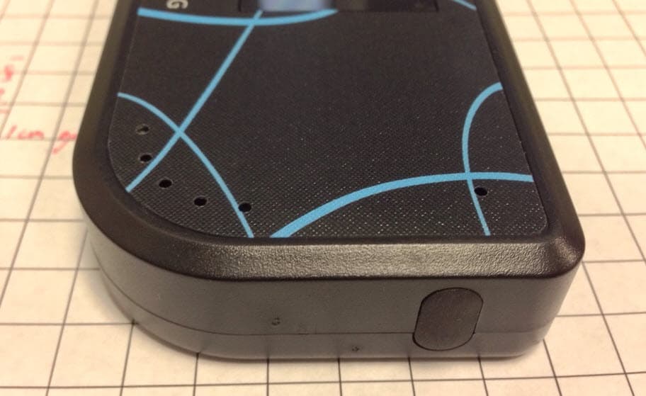
ZIMTZMR3G
Nov 04, 2014Ambulatory electrocardiograph monitor
Equipment Class
PCT - PCS Licensed Transmitter worn on body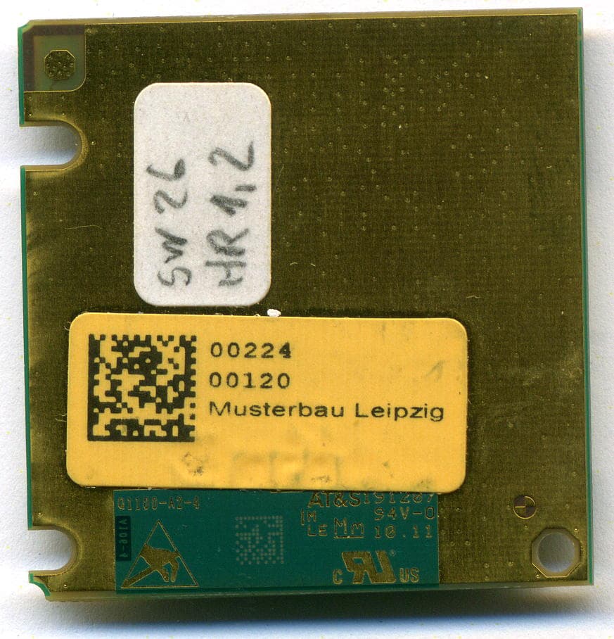
ZIMTZMR
Apr 11, 2012AERA CT MOBILE CARDIAC MONITOR
Equipment Class
PCT - PCS Licensed Transmitter worn on body