ZJVBT712SBT712S, PWFMT11, C69D, IABT220B
Premier Accessory Group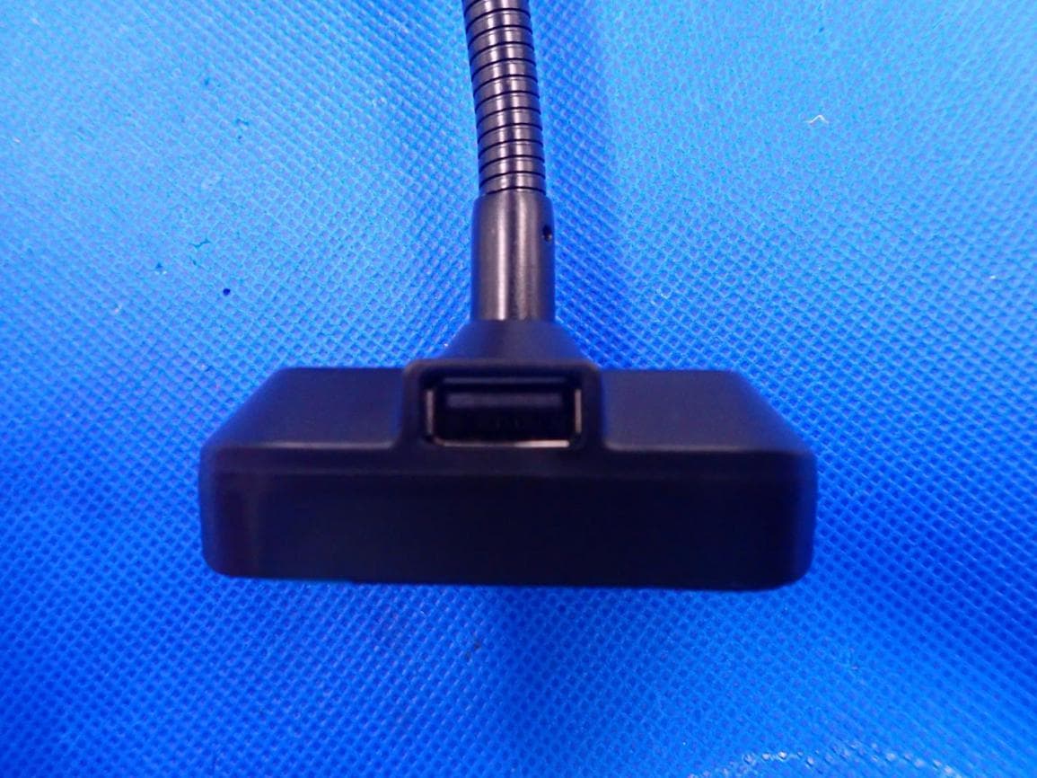
Click to zoom
Application Details
- Equipment Class
- DSS - Part 15 Spread Spectrum Transmitter
- Date of Grant
- Jul 29, 2020
- Application Purpose
- Original Equipment
- Date of Application
- Jul 29, 2020
- Equipment Note
- BT712S, PWFMT11, C69D, IABT220B
- Frequency Range
- 2402.00000000 - 2480.00000000
- Company
- Premier Accessory Group
- Country
- United States
Documents & Files
Document Text
Text extracted from the exhibit documents filed with the FCC. Open a document above to read the original.
Users Manual
BLUETOOTH HANDS FREE CAR KIT with FM Transmitter and Bass Boost Functionality BT712S (PWFMT11) Thanks for choosing our Bluetooth FM Transmitter. This device streams music and phone calls directly from your Bluetooth device to the car FM stereo system. The built-in microphone provides you with an amazing hands free function, it is also with a Micro SD card/USB Disk slot that lets you enjoy favorite MP3 and WMA tunes by your car’s stereo system and charge your phone simultaneously. It also can deliver a deeper bass by pressing the bass button when playing the music. Please read the User Manual carefully before using it. Hope this device makes your driving more interesting and safer. Packing contents: Bluetooth FM Transmitter User Guide Features: 1. Wireless transmit phone call & audio playing to the car FM stereo system via Bluetooth; 2. Switch to Hands-free mode automatically from music playing status when receiving calls; 3. Adjustable goose-neck design allows us to find a better viewing; 4. Elegant design with big white LED display; 5. Support to read Micro SD ( Max 32 GB); 6. Dual USB output QC3.0+DC 5V/2.4A; 7. Voice prompt and hands-free calling for safety driving; 8. Adopt the Bluetooth 5.0 Technology; 9. Siri/Google assistant quick activation. Specifications: Bluetooth Version: 5.0; Frequency range: 88.1-107.9MHZ; Frequency stability: ±10ppm; Product Input:12-24V; Dual USB output: QC3.0+DC 5V/2.4A; Micro SD Card (Max Capacity) :32GB; Music Format: MP3/WMA/WAV/FLAC; Product Dimension: 59*90*127 mm; Product Weight: 73.3g; Compatibility: This device can be paired as a hands free kit with any compatible Bluetooth 2.1 or higher enabled devices. Precautions: Please read all safety instruction warnings carefully before using this product. Improper use of this product may result in damage to this or attached products. To ensure the products work well, please never use this in the following conditions: 1. Moist or underwater conditions. 2. Conditions near heater or high-temperature service. 3. Conditions with direct and strong sunshine, 4. Never dismantle the product without due permission, otherwise it may nullify the warranty clause. Appearance: Operation Instructions Setup the FM Transmitter Connection: 1. Plug the unit into your vehicle’s cigarette lighter or power port. 2. Tune your radio to an unused FM frequency, then match the same frequency of this unit. 3. Insert Micro SD card or USB disk which containing MP3/WMA files into the card/USB slot. It will play and transmit the file automatically. Using Bluetooth function: 1. Using Bluetooth for the first time, you need to pair your mobile phone with this unit. Activate your mobile phone's Bluetooth function, then search new device. When the mobile phone detects this unit (named as "PWFMT11"), please pair or connect. 2. On music playing mode, when there is an incoming call, this unit will automatically switch to telephone mode. Bluetooth calling: 1. Please press to answer the incoming call or hang off a call. 2. Please press and hold for 3 seconds during call to reject the incoming call in Bluetooth calling mode. 3. Please press twice to dial the last Number automatically. 4. When making a call, you can only dial the phone number by your mobile phone, but once the call connected, you can use the hands-free function to enjoy it. HOW TO ACTIVATE VOICE ASSISTANT (e.g. Siri/Google assistant) Press “” hold for 2 seconds to quickly access voice assistant. Quick Guide: Operation Guide On FM transmitter 1. Answe/hang up the call: Press "" button: answer the call Press "" button: hang up the call 2. Ignore call Press “ ” and hold for 3 seconds to reject incoming calls 3. Call last Number Press “” twice to dial the last Number automatically. 4. Private calling When answering a call ,press “” and hold for 3 seconds to switch to private call mode. 5. Play and Pause the music: Press “” Button: Play the music Press “” Button again: Pause playing 6. Adjust the Volume: Press”˄”and hold for 2 seconds to increase the Volume Press”˅” and hold for 2 seconds to decrease Volume 7.Set frequency: press “CH” and then press ”˄” to increase the frequency Press ”CH” and then press ”˅” to decrease the frequency 8.Choose music: Press ”˅” Button: Play the next song Press ”˄” Button: Play the previous song NOTE: This equipment has been tested and found to comply with the limits for a Class B digital device, pursuant to part 15 of the FCC Rules. These limits are designed to provide reasonable protection against harmful interference in a residential installation. This equipment generates uses and can radiate radio frequency energy and, if not installed and used in accordance with the instructions, may cause harmful interference to radio communications. However, there is no guarantee that interference will not occur in a particular installation. If this equipment does cause harmful interference to radio or television reception, which can be determined by turning the equipment off and on, the user is encouraged to try to correct the interference by one or more of the following measures: - Reorient or relocate the receiving antenna. - Increase the separation between the equipment and receiver. -Connect the equipment into an outlet on a circuit different from that to which the receiver is connected. -Consult the dealer or an experienced radio/TV technician for help Changes or modifications not expressly approved by the party responsible for compliance could void the user's authority to operate the equipment. This device complies with Part 15 of the FCC Rules. Operation is subject to the following two conditions: (1) this device may not cause harmful interference, and (2) this device must accept any interference received, including interference that may cause undesired operation.
Cover Letter(s)
Premier Accessory Group Agent Authorization Company: Premier Accessory Group Address: 21 Commerce Drive Cranbury, NJ 08512 Product Name: Bluetooth FM Transmitter Model Number(s): BT712S, PWFMT11, C69D, IABT220B Product Description: Bluetooth FM Transmitter We authorize MiCOM Labs Inc., 575 Boulder Court, Pleasanton, California 94566, USA, to act on our behalf on all matters concerning the certification of above named equipment. We declare that MiCOM Labs Inc. is allowed to forward all information related to the approval and certification of equipment to the regulatory agencies as required and to discuss any issues concerning the approval application. Any and all acts carried out by MiCOM Labs on our behalf shall have the same effect as acts of our own. Signature: Date: 2020-07-27 Name: Albert Esses Company: Premier Accessory Group
External Photos
External Photos TOP VIEW OF EUT BOTTOM VIEW OF EUT FRONT VIEW OF EUT BACK VIEW OF EUT LEFT VIEW OF EUT RIGHT VIEW OF EUT VIEW OF EUT(PORT)-1 VIEW OF EUT(PORT)-2 VIEW OF EUT(PORT)-3
RF Exposure Info
RF EXPOSURE EVALUATION 1. PRODUCT INFORMATION Product Description Bluetooth FM Transmitter Model Name BT712S, PWFMT11, C69D, IABT220B FCC ID ZJVBT712S 2. EVALUATION METHOD According to 447498 D01 General RF Exposure Guidance v05 The 1-g and 10-g SAR test exclusion thresholds for 100 MHz to 6 GHz at test separation distances ≤ 50 mm are determined by: [(max. power of channel, including tune-up tolerance, mW)/(min. test separation distance, mm)] ·[√f(GHz)] ≤ 3.0 for 1-g SAR and ≤ 7.5 for 10-g extremity SAR. Where f(GHz) is the RF channel transmit frequency in GHz Power and distance are rounded to the nearest mW and mm before calculation 3. CALCULATION P t =2.113dBm=1.63mW The value of the Maximum output power P t is referred to the test report of the CFR47 §15.247. The result for RF exposure evaluation SAR=(1.63mW /5mm) * [√2.402GHz)]= 0.51<3.0 for 1-g SAR and ≤ 7.5 for 10-g extremity SAR. §15.239 FM Pt=-51.43dBm=0.0000072mW The value of the Maximum output power P t is referred to the test report of the CFR47 For frequencies below 100 MHz and test separation distances ≤ 50 mm,the power threshold determined by the following: P max =0.5 * 474 * [1+log(100/f)] mW, where f is MHz For 88.1MHz, P max =250mW. Pt< P max. For 107.9MHz, P = 3 x 5 / 0.1079^0.5 = 45.7 mW P max =45.7mW. Pt< P max. Simultaneous transmission between Bluetooth and FM transmitter: [(max. power of channel, including tune-up tolerance, mW) / (min. test separation distance, mm)]·[√f(GHz)/x] W/kg, for test separation distances ≤ 50 mm; where x = 7.5 for 1-g SAR and x = 18.75 for 10-g SAR. SAR=(0.51+0. 0000004723)/7.5=0.068W/kg<1.6W/kg 4. CONCLUSION The SAR evaluation is not required.
Test Report
Page 1 of 68 FCC Test Report Report No.: AGC08409200511FE03 FCC ID : ZJVBT712S APPLICATION PURPOSE : Original Equipment PRODUCT DESIGNATION : Bluetooth FM Transmitter BRAND NAME : Premier MODEL NAME : BT712S, PWFMT11, C69D, IABT220B APPLICANT : Premier Accessory Group DATE OF ISSUE : Jul. 13, 2020 STANDARD(S) : FCC Part 15.247 REPORT VERSION : V1.0 Attestation of Global Compliance (Shenzhen) Co., Ltd CAUTION: This report shall not be reproduced except in full without the written permission of the test laboratory and shall not be quoted out of context. Report No.: AGC08409200511FE03 Page 2 of 68 REPORT REVISE RECORD Report Version Revise Time Issued Date Valid Version Notes V1.0 / Jul. 13, 2020 Valid Initial Release Report No.: AGC08409200511FE03 Page 3 of 68 TABLE OF CONTENTS 1. VERIFICATION OF CONFORMITY ............................................................................................................... 5 2. GENERAL INFORMATION ............................................................................................................................ 6 2.1. PRODUCT DESCRIPTION ..................................................................................................................... 6 2.2. TABLE OF CARRIER FREQUENCYS ..................................................................................................... 6 2.3. RECEIVER INPUT BANDWIDTH ............................................................................................................ 7 2.4. EXAMPLE OF A HOPPING SEQUENCY IN DATA MODE ....................................................................... 7 2.5. EQUALLY AVERAGE USE OF FREQUENCIES AND BEHAVIOUR ........................................................ 7 2.6. RELATED SUBMITTAL(S) / GRANT (S) .................................................................................................. 8 2.7. TEST METHODOLOGY .......................................................................................................................... 8 2.8. SPECIAL ACCESSORIES ....................................................................................................................... 8 2.9. EQUIPMENT MODIFICATIONS .............................................................................................................. 8 3. MEASUREMENT UNCERTAINTY ................................................................................................................. 9 4. DESCRIPTION OF TEST MODES ............................................................................................................... 10 5. SYSTEM TEST CONFIGURATION ............................................................................................................. 11 5.1. CONFIGURATION OF EUT SYSTEM .................................................................................................... 11 5.2 EQUIPMENT USED IN TESTED SYSTEM .............................................................................................. 11 5.3. SUMMARY OF TEST RESULTS ............................................................................................................. 11 6. TEST FACILITY ........................................................................................................................................... 12 7. PEAK OUTPUT POWER ............................................................................................................................. 13 7.1. MEASUREMENT PROCEDURE ........................................................................................................... 13 7.2. TEST SET-UP (BLOCK DIAGRAM OF CONFIGURATION) ................................................................... 13 7.3. LIMITS AND MEASUREMENT RESULT ............................................................................................... 14 8. 20DB BANDWIDTH ..................................................................................................................................... 20 8.1. MEASUREMENT PROCEDURE ........................................................................................................... 20 8.2. TEST SET-UP (BLOCK DIAGRAM OF CONFIGURATION) ................................................................... 20 8.3. LIMITS AND MEASUREMENT RESULTS ............................................................................................. 21 9. CONDUCTED SPURIOUS EMISSION ........................................................................................................ 27 9.1. MEASUREMENT PROCEDURE ........................................................................................................... 27 9.2. TEST SET-UP (BLOCK DIAGRAM OF CONFIGURATION) ................................................................... 27 9.3. MEASUREMENT EQUIPMENT USED .................................................................................................. 27 Report No.: AGC08409200511FE03 Page 4 of 68 9.4. LIMITS AND MEASUREMENT RESULT ............................................................................................... 27 10. RADIATED EMISSION ............................................................................................................................... 40 10.1. MEASUREMENT PROCEDURE ......................................................................................................... 40 10.2. TEST SETUP ....................................................................................................................................... 42 10.3. LIMITS AND MEASUREMENT RESULT ............................................................................................. 43 10.4. TEST RESULT ..................................................................................................................................... 43 11. NUMBER OF HOPPING FREQUENCY ..................................................................................................... 53 11.1. MEASURE…
Text truncated - open the document above for the full version.
Test Report
Report No.: AGC08409200511FE03 Page 52 of 68 EUT Bluetooth FM Transmitter Model Name BT712S Temperature 25°C Relative Humidity 55.4% Pressure 960hPa Test Voltage Normal Voltage Test Mode Mode 3 Antenna Vertical PK AV RESULT: PASS Note: The factor had been edited in the “Input Correction” of the Spectrum Analyzer. The GFSK modulation is the worst case and recorded in the report. Report No.: AGC08409200511FE03 Page 53 of 68 11. NUMBER OF HOPPING FREQUENCY 11.1. MEASUREMENT PROCEDURE The EUT shall have its hopping function enabled. Use the following spectrum analyzer settings: 1. Span: The frequency band of operation. Depending on the number of channels the device supports, it may be necessary to divide the frequency range of operation across multiple spans, to allow the individual channels to be clearly seen. 2. RBW: To identify clearly the individual channels, set the RBW to less than 30% of the channel spacing or the 20 dB bandwidth, whichever is smaller. 3. VBW ≥ RBW. Sweep: Auto. Detector function: Peak. Trace: Max hold. 4. Allow the trace to stabilize. 11.2. TEST SETUP (BLOCK DIAGRAM OF CONFIGURATION) Same as described in section 8.2 11.3. MEASUREMENT EQUIPMENT USED The same as described in section 6 11.4. LIMITS AND MEASUREMENT RESULT TOTAL NO. OF HOPPING CHANNEL LIMIT (NO. OF CH) MEASUREMENT (NO. OF CH) RESULT >=15 79 PASS TEST PLOT FOR NO. OF TOTAL CHANNELS Note: The GFSK modulation is the worst case and recorded in the report. Report No.: AGC08409200511FE03 Page 54 of 68 12. TIME OF OCCUPANCY (DWELL TIME) 12.1. MEASUREMENT PROCEDURE The EUT shall have its hopping function enabled. Use the following spectrum analyzer settings: 1. Span: Zero span, centered on a hopping channel. 2. RBW shall be≤channel spacing and where possible RBW should be set >> 1 / T, where T is the expected dwell time per channel. 3. Sweep: As necessary to capture the entire dwell time per hopping channel; where possible use a video trigger and trigger delay so that the transmitted signal starts a little to the right of the start of the plot. The trigger level might need slight adjustment to prevent triggering when the system hops on an adjacent channel; a second plot might be needed with a longer sweep time to show two successive hops on a channel. 4. Detector function: Peak. Trace: Max hold. 5. Use the marker-delta function to determine the transmit time per hop. 6. Repeat the measurement using a longer sweep time to determine the number of hops over the period specified in the requirements. The sweep time shall be equal to, or less than, the period specified in the requirements. Determine the number of hops over the sweep time and calculate the total number of hops in the period specified in the requirements, using the following equation: (Number of hops in the period specified in the requirements) = (number of hops on spectrum analyzer) × (period specified in the requirements / analyzer sweep time) 7. The average time of occupancy is calculated from the transmit time per hop multiplied by the number of hops in the period specified in the requirements. 12.2. TEST SETUP (BLOCK DIAGRAM OF CONFIGURATION) Same as described in section 8.2 12.3. MEASUREMENT EQUIPMENT USED The same as described in section 6 12.4. LIMITS AND MEASUREMENT RESULT Channel Time of Pulse for DH5 (ms) Number of hops in the period specified in the requirements Sweep Time (ms) Limit (ms) Low 2.890 26*4 301.60 400 Middle 2.890 28*4 323.68 400 High 2.890 25*4 289.00 400 Note: The GFSK modulation is the worst case and recorded in the report. Report No.: AGC08409200511FE03 Page 55 of 68 TEST PLOT OF LOW CHANNEL Report No.: AGC08409200511FE03 Page 56 of 68 TEST PLOT OF MIDDLE CHANNEL Report No.: AGC08409200511FE03 Page 57 of 68 TEST PLOT OF HIGH CHANNEL Report No.: AGC08409200511FE03 Page 58 of 68 13. FREQUENCY SEPARATION 13.1. MEASUREMENT PROCEDURE The EUT shall have its hopping function enabled. Use the following spectrum analyzer settings: 1. Span: Wide enough to capture the peaks of two adjacent channels. 2. RBW: Start with the RBW set to approximately 30% of the channel spacing; adjust as necessary to best identify the center of each individual channel. 3. Video (or average) bandwidth (VBW) ≥ RBW. 4. Sweep: Auto. e) Detector function: Peak. f) Trace: Max hold. g) Allow the trace to stabilize. Use the marker-delta function to determine the separation between the peaks of the adjacent channels. 13.2. TEST SETUP (BLOCK DIAGRAM OF CONFIGURATION) Same as described in section 6.2 13.3. MEASUREMENT EQUIPMENT USED The same as described in section 6.3 13.4. LIMITS AND MEASUREMENT RESULT CHANNEL CHANNEL SEPARATION LIMIT RESULT MHz KHz Pass CH01-CH02 1.005 >= 2/3 20 dB BW TEST PLOT FOR FREQUENCY SEPARATION Note: The 8-DPSK modulation is the worst case and recorded in the report. Report No.: AGC08409200511FE03 Page 59 of 68 APPENDIX A: PHOTOGRAPHS OF TEST SETUP RADIATED EMISSION TEST SETUP BELOW 1GHZ RADIATED EMISSION TEST SETUP ABOVE 1GHZ Report No.: AGC08409200511FE03 Page 60 of 68 APPENDIX B: PHOTOGRAPHS OF EUT TOP VIEW OF EUT BOTTOM VIEW OF EUT Report No.: AGC08409200511FE03 Page 61 of 68 FRONT VIEW OF EUT BACK VIEW OF EUT Report No.: AGC08409200511FE03 Page 62 of 68 LEFT VIEW OF EUT RIGHT VIEW OF EUT Report No.: AGC08409200511FE03 Page 63 of 68 VIEW OF EUT(PORT)-1 VIEW OF EUT(PORT)-2 Report No.: AGC08409200511FE03 Page 64 of 68 VIEW OF EUT(PORT)-3 OPEN VIEW OF EUT Report No.: AGC08409200511FE03 Page 65 of 68 INTERNAL VIEW-1 OF EUT INTERNAL VIEW-2 OF EUT Report No.: AGC08409200511FE03 Page 66 of 68 INTERNAL VIEW-3 OF EUT INTERNAL VIEW-4 OF EUT Report No.: AGC08409200511FE03 Page 67 of 68 INTERNAL VIEW-5 OF EUT INTERNAL VIEW-6 OF EUT BT Antenna Report No.: AGC08409200511FE03 Page 68 of 68 INTERNAL VIEW-7 OF EUT ----END OF REPORT---- FM Antenna
Test Setup Photos
Test Setup Photos RADIATED EMISSION TEST SETUP BELOW 1GHZ RADIATED EMISSION TEST SETUP ABOVE 1GHZ
Contact Information
Applicant
Albert Esses(Executive VP)
Technical Contact
Test Firm
Attestation of Global Compliance (Shenzhen) Co., LDoris Li
[email protected]+86-755-25234088
Technical Specifications
| # | Rule Parts | Frequency Range | Power Output |
|---|---|---|---|
| 1 | 15C | 2.40 GHz - 2.48 GHz | 1.60 mW |
Other Applications from Premier Accessory Group
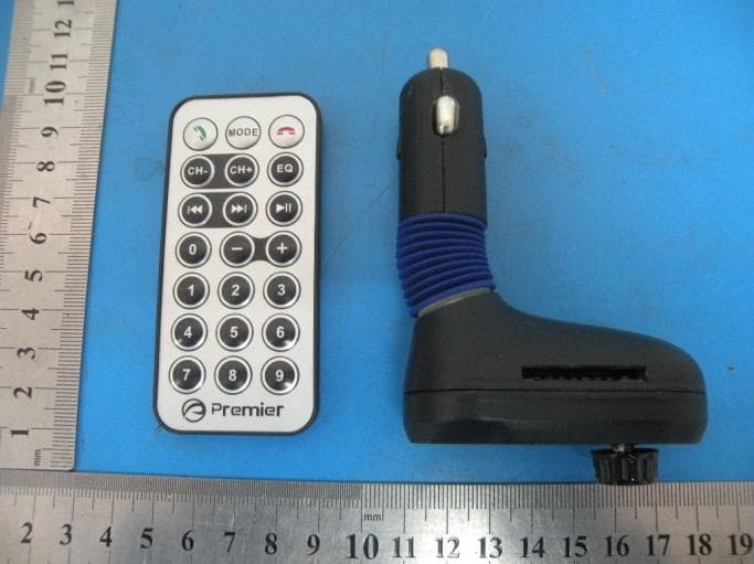
ZJV-PWFMT4
Jan 16, 2015Car MP3 bluetooth transmitter
Equipment Class
DXX - Part 15 Low Power Communication Device Transmitter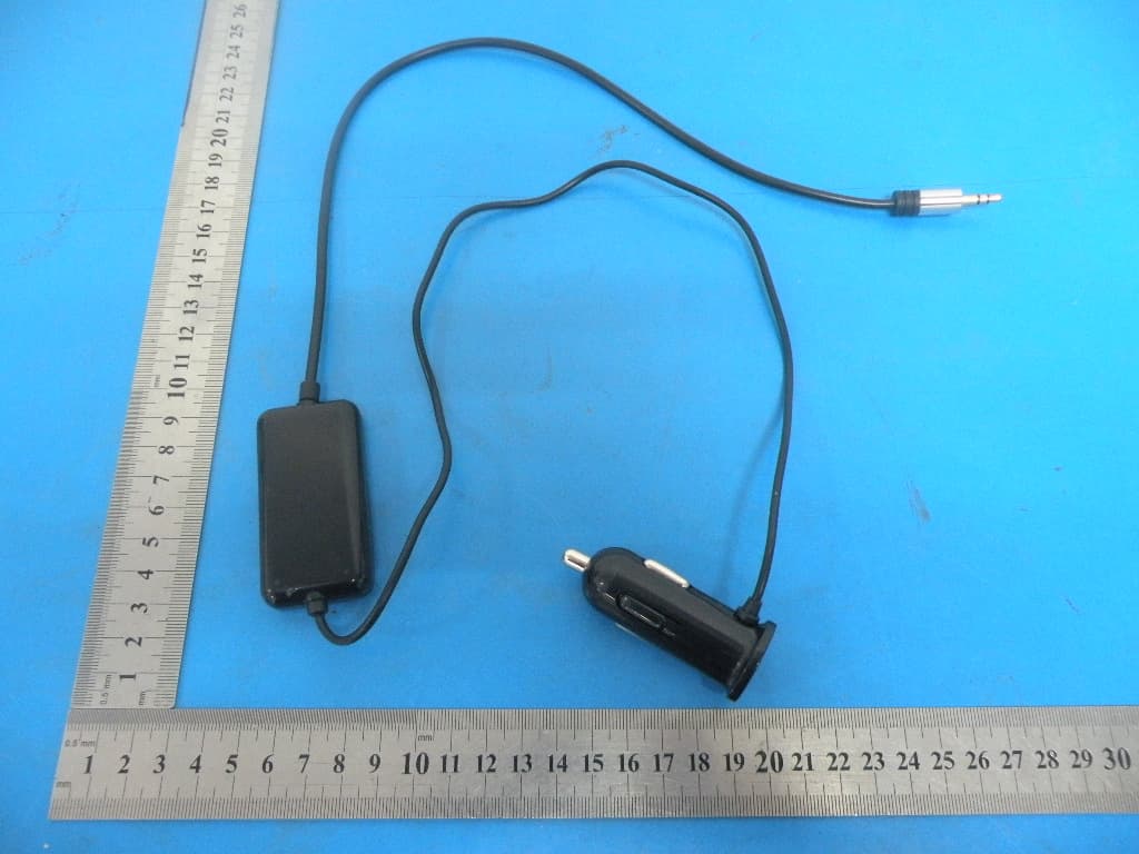
ZJV-ENGFMT4
Jan 16, 2015FM Transmitter
Equipment Class
DXX - Part 15 Low Power Communication Device Transmitter
ZJVPWFMT1
Jul 27, 2014FM Transmitter
Equipment Class
DXX - Part 15 Low Power Communication Device Transmitter
ZJVPWFMT3
Jul 26, 2014FM Transmitter
Equipment Class
DXX - Part 15 Low Power Communication Device Transmitter
ZJVP01
Jul 17, 2014Bluetooth Headset
Equipment Class
DSS - Part 15 Spread Spectrum Transmitter