ZKI-BEG200Smart Ethernet Gateway
VOXLAND SARL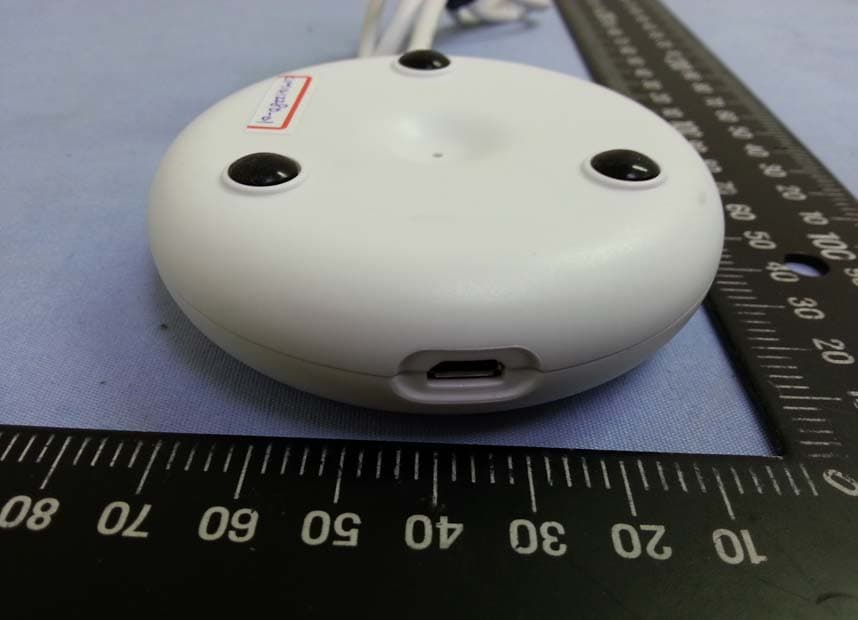
Click to zoom
Application Details
- Equipment Class
- DTS - Digital Transmission System
- Date of Grant
- Jun 03, 2015
- Application Purpose
- Original Equipment
- Date of Application
- Jun 02, 2015
- Equipment Note
- Smart Ethernet Gateway
- Frequency Range
- 2402.00000000 - 2480.00000000
- Company
- VOXLAND SARL
- Country
- France (European Territory)
Documents & Files
Document Text
Text extracted from the exhibit documents filed with the FCC. Open a document above to read the original.
Users Manual
BEG200 User Manual v1.1 1 BEG200 Smart Ethernet Gateway User Manual Thank you for purchasing the BEG200 Smart Gateway from BEEWI. Please read the following instructions to learn how to configure and use more effectively your product. Introduction The Ethernet Gateway is a Bluetooth Smart Gateway which can bridge various smart peripherals to the Internet via a router using the provided Ethernet interface. With the Ethernet Gateway it is possible to remotely control all BeeWi Bluetooth Smart peripherals such as smart plugs, smart bulbs or smart sensors using a web server and/or the associated web applications. 1. PRODUCT DESCRIPTION 1.1. Product Outlook - Micro-USB power connector - Status LEDs: Bluetooth (blue) and Ethernet (green) - Pairing button (top) - Reboot button (back) - Ethernet cable 1.2. Package Content - Smart Ethernet Gateway - USB to micro-USB cable - Quick Start Guide and other info 1.3. Main features - Simply bridging your BeeWi Smart peripherals to the BeeWi Home cloud server to bring Internet of Things to your home - Simple and easy to install with Ethernet connection to any Internet router - Controlled via a dedicated server and associated web apps for Smartphone and tablets. - Compact size, low weight. - Long range, up to 60 meters, with integrated RF amplifier. - Fully evolutive with firmware updates supported via the server. BEG200 User Manual v1.1 2 1.4. Specifications Radio Bluetooth Low Energy, +10 dBm Range Up to 50 meters Ethernet 100Base10, 100 Mbps Power 5V typical, Micro-USB connector Consumption 1 W typical Dimensions Approx. Ø78mm x H22mm (Diameter x Height) Weight Approx. 50g LAN cable length Approx. 50 cm USB cable length Approx. 50 cm 2. INSTALLATION 2.1. Connection to the router The Gateway requires both USB power source and Ethernet port to connect to the router. Most of the routers provide both interface but you can also use a standard USB power adapter (not provided) in case no USB port is available on your router. 1) Plug the USB to micro USB cable to the router’s USB port 2) Plug the Gateway’s Ethernet cable to one of the router’s Ethernet port 3) Connect the USB cable to the Gateway micro-USB port The Gateway’s blue LED will start flashing once every 2 seconds before the green LED turns on to confirm connection to the server. 2.2. Account setting Once the Gateway is connected to the server (green LED on), it is possible to create a user account associated with the Gateway on the server. To do this: 1) Open your web browser and go to www.beewi-home.com 2) Go to “Create an account” 3) Type in all necessary information Note you will be required to enter the Gateway MAC address and serial number which can be found on a label on the back of the Gateway. Once this is done, the home page will be automatically opened and you will see the Gateway listed on top of it. 2.3. Pairing a peripheral In order to register a new BeeWi Smart peripheral as part of the www.beewi-home.com network, it is necessary to pair it securely with the Gateway. To do this, follow these steps: 1) Press the Gateway pairing button: the blue LED flashes twice per second to initiate pairing. 2) Turn the Smart peripheral in discoverable mode (operation depends on the peripheral, refer to the user guide). It will be visible for pairing during 30 to 60 seconds. 3) Once the Smart peripheral has been successfully paired with the Gateway, the new peripheral will show in the web app home screen. It this is not the case, just actualize the window using the “Actualize” button on the top left. Note: make sure your peripheral is updated with the most recent firmware in order to work BEG200 User Manual v1.1 3 properly with the Gateway. 2.4. Reboot It may necessary to reboot the gateway in case the link to the network is lost (green LED turned off). To reset the gateway, simply push the button on the back. Note resetting the gateway does not affect all the settings. 2.5. Factory Restore The Gateway can be restored to factory default state including factory firmware version. To restore the firmware and delete all pairing or status user data, just press the function button whilst inserting the USB cable. Restoration is confirmed by means of the Led indicator blinking quickly for a few seconds. 3. USING THE WEB SERVER 3.1. Introduction Once you have created your account and added all the peripherals you wish to control remotely, go to the www.beewi-home.com portal under your own account using a web browser or the web app to view and access them. More information regarding the functioning of the web server can be found in the Help page. 3.2. Main screen The main page (or left panel in computer and tablet views) shows the list of peripherals with the following information organized in boxes for each peripheral: - Peripheral type and name - Connection status and active mode - Actual parameters such as temperature, humidity, LED color and brightness, etc. - On/Off buttons for actionable peripherals 3.3. Peripheral screen By clicking on a specific peripheral, the Control page is opened ( or right control panel in computer and tablet views), giving access to all control functions such as: - Mode settings - Alert settings - History - Edition BEG200 User Manual v1.1 4 CAUTION & WARRANTY EXCEPTIONS 5.1. Taking care of your Product • Use the product indoor only. • Avoid storage at extreme temperatures, above 45°C (including direct sunlight) or below -10°C. This can shorten battery life and may affect operation. • Do not expose the product to rain or moisture. • When not in use, always store the product in a safe place. 5.2. Damages not covered by standard Warranty • Damages caused by an improper use of the product such as shocks, drops, exposition to extreme temperatures, dust, or humidity, or any other cause. • Damages resulting from any non-respect of manufacturer instructions. • Cosmetic damages such as scratches, paint, glue or any other alteration made to the product. • Damages to the product after a repai…
Text truncated - open the document above for the full version.
Attestation Statements
For the following information Ref. File No.: C1M1412280 Product Smart Ethernet Gateway Model Number BEG200 Brand Name BeeWi Applicant VOXLAND SARL Manufacturer Dongguan Quan Sheng Electric Co. Ltd. Standards FCC 47 CFR Part 15 Subpart B/Oct. 2013 and CISPR 22/1997 and ICES-003 Issue 5 Aug. 2012 (Class B Limit) We hereby certify that the above product has been tested by us and complied with the FCC and IC official limits. The product might be marketed in US in accordance with the standard CFR 47 Part 2 and Part 15 Subpart B class B equipment regulations under FCC Rules. The test was performed according to the procedures mentioned in ANSI C63.4-2009. The test data and results are issued on the test report no.EM-F140822. Signature _____________________________ Ben Cheng/Manager Date: 2014. 12. 29 Test Laboratory: AUDIX Technology Corporation, EMC Department NVLAP Lab. Code: 200077-0 FCC OET Designation: TW1004 Web Site: www.audixtech.com The statement is based on a single evaluation of one sample of the above-mentioned products. It does not imply an assessment of the whole production and does not permit the use of the test lab logo. NVLAP Lab Code 200077-0
Cover Letter(s)
Authority to Act as Agent Date: October 16, 2014 American Certification Body, Inc. 6731 Whittier Avenue Suite C110 McLean, VA 22101 To Whom It May Concern: _____AUDIX Technology Corporation______ is authorized to act on our behalf, until otherwise notified, for applications to American Certification Body, Inc. (ACB). We certify that we are not subject to denial of federal benefits, that includes FCC benefits, pursuant to Section 5301 of the Anti-Drug Abuse Act of 1988, 21 U.S.C. 862. Further, no party, as defined in 47 CFR 1.2002 (b), to the application is subject to denial of federal benefits, that includes FCC benefits. Thank you, Agency Agreement Expiration Date: ____October 14, 2015_____ By: __________________________ __ Jerome Plateau______ (Signature) (Print name) Title: ____Portfolio Manager ________ On behalf of: __ _VOXLAND SARL________ (Company Name) Telephone: ____0033607013155 _________
Cover Letter(s)
Request for Confidentiality Date: December 29, 2014 Federal Communications Commission Authorization and Evaluation Division Subject: Confidentiality Request regarding Application for certification of FCC ID: ZKI-BEG200 Gentlemen: Pursuant to Section 0.457 and 0.459 of the Commission’s Rules, we hereby request confidential treatment of information accompanying this application as outlined below: Functional Block Diagram Operational Description (theory of operation) Schematic Diagram The above materials contain trade secrets and proprietary information not customarily released to the public. The public disclosure of these materials may be harmful to the applicant and provide unjustified benefits to its competitors. The Applicant understands that pursuant to Section 0.457 of the Rules, disclosure of this application and all accompanying documentation will not be made before the date of the Grant for this application. Sincerely, _______________________________________ Jerome Plateau Portfolio Manager VOXLAND SARL
External Photos
VOXLAND SARL Smart Ethernet Gateway FCC ID. : ZKI-BEG200 IC: 9713A-BEG200 EUT External Photos Figure 1 General Appearance (Front & Side View) Figure 2 General Appearance (Back & Side View) VOXLAND SARL Smart Ethernet Gateway FCC ID. : ZKI-BEG200 IC: 9713A-BEG200 Figure 3 General Appearance (USB Port)
ID Label/Location Info
VOXLAND SARL Smart Ethernet Gateway FCC ID. : ZKI-BEG200 IC: 9713A-BEG200 FCC ID & IC Label Location z Label Placement Location z FCC ID & IC Label Format FCC ID & IC Label Placement Location
Internal Photos
VOXLAND SARL Smart Ethernet Gateway FCC ID. : ZKI-BEG200 IC: 9713A-BEG200 EUT Internal Photos Figure 4 Internal View (Removed Covers) Figure 5 Internal View (Main Board, Front View) Antenna VOXLAND SARL Smart Ethernet Gateway FCC ID. : ZKI-BEG200 IC: 9713A-BEG200 Figure 6 Internal View (Main Board, Back View)
Test Report
Page 1 of 40 AUDIX Technology Corp. Tel: +886 2 26099301 No. 53-11, Dingfu, Linkou, Dist., Fax: +886 2 26099303 New Taipei City244, Taiwan File Number: C1M1412280 Report Number: EM-F140823 This test report may be reproduced in full only. The document may only be updated by AUDIX Technology Corp. personnel Any changes will be noted in the Document History section of the report. FCC 15.247 2.4 GHz Report for VOXLAND SARL CS90234 - 13311 Marseille Cedex 14 Brand : BeeWi Product Name : Smart Ethernet Gateway Model Name : BEG200 FCC ID : ZKI-BEG200 Page 2 of 40 AUDIX Technology Corp. Tel: +886 2 26099301 No. 53-11, Dingfu, Linkou, Dist., Fax: +886 2 26099303 New Taipei City244, Taiwan File Number: C1M1412280 Report Number: EM-F140823 This test report may be reproduced in full only. The document may only be updated by AUDIX Technology Corp. personnel Any changes will be noted in the Document History section of the report. TABLE OF CONTENTS Description Page TEST REPORT CERTIFICATION ............................................................................................. 4 1. REPORT HISTORY.............................................................................................................. 5 2. SUMMARY OF TEST RESULTS ....................................................................................... 6 3. GENERAL INFORMATION ............................................................................................... 7 3.1. Description of EUT ..................................................................................................................... 7 3.2. EUT Specifications Assessed in Current Report ...................................................................... 8 3.3. Antenna Information .................................................................................................................. 9 3.4. Test Configuration ...................................................................................................................... 9 3.5. Tested Supporting System List ................................................................................................ 10 3.6. Setup Configuration ................................................................................................................. 10 3.7. Operating Condition of EUT ................................................................................................... 10 3.8. Description of Test Facility ...................................................................................................... 11 3.9. Measurement Uncertainty ....................................................................................................... 11 4. MEASUREMENT EQUIPMENT LIST ............................................................................ 12 4.1. Conducted Emission Measurement ......................................................................................... 12 4.2. Radiated Emission Measurement ............................................................................................ 12 4.3. RF Conducted Measurement ................................................................................................... 12 5. CONDUCTED EMISSION MEASUREMET ................................................................... 13 5.1. Block Diagram of Test Setup ................................................................................................... 13 5.2. Power Line Conducted Emission Limit .................................................................................. 13 5.3. Test Procedure .......................................................................................................................... 13 5.4. Conducted Emission Measurement Results ........................................................................... 14 6. RADIATED EMISSION MEASUREMENT .................................................................... 16 6.1. Block Diagram of Test Setup ................................................................................................... 16 6.2. Radiated Emission Limits ........................................................................................................ 17 6.3. Test Procedure .......................................................................................................................... 17 6.4. Measurement Result Explanation ........................................................................................... 18 6.5. Test Results ................................................................................................................................ 18 7. 6dB BANDWIDTH MEASUREMENT ............................................................................. 27 7.1. Block Diagram of Test Setup ................................................................................................... 27 7.2. Specification Limits .................................................................................................................. 27 7.3. Test Procedure .......................................................................................................................... 27 7.4. Test Results ................................................................................................................................ 27 8. MAXIMUM PEAK OUTPUT POWER MEASUREMENT ........................................... 29 8.1. Block Diagram of Test Setup ................................................................................................... 29 8.2. Specification Limits .................................................................................................................. 29 8.3. Test Procedure .......................................................................................................................... 29 8.4. Test Results ................................................................................................................................ 30 9. EMIS…
Text truncated - open the document above for the full version.
Test Setup Photos
APPENDIX A AUDIX Technology Corp. Tel: +886 2 26099301 No. 53-11, Dingfu, Linkou, Dist., Fax: +886 2 26099303 New Taipei City244, Taiwan File Number: C1M1412280 Report Number: EM-F140823 This test report may be reproduced in full only. The document may only be updated by AUDIX Technology Corp. personnel Any changes will be noted in the Document History section of the report. APPENDIX A TEST PHOTOGRAPHS (Model: BEG200) APPENDIX A-Page 1 of 3 AUDIX Technology Corp. Tel: +886 2 26099301 No. 53-11, Dingfu, Linkou, Dist., Fax: +886 2 26099303 New Taipei City244, Taiwan File Number: C1M1412280 Report Number: EM-F140823 This test report may be reproduced in full only. The document may only be updated by AUDIX Technology Corp. personnel Any changes will be noted in the Document History section of the report. A.1 Conducted Emission Measurement FRONT VIEW Back VIEW APPENDIX A-Page 2 of 3 AUDIX Technology Corp. Tel: +886 2 26099301 No. 53-11, Dingfu, Linkou, Dist., Fax: +886 2 26099303 New Taipei City244, Taiwan File Number: C1M1412280 Report Number: EM-F140823 This test report may be reproduced in full only. The document may only be updated by AUDIX Technology Corp. personnel Any changes will be noted in the Document History section of the report. A.2 Radiated Measurement at Semi-Anechoic Chamber Frequency Below 1GHz Frequency Above 1GHz APPENDIX A-Page 3 of 3 AUDIX Technology Corp. Tel: +886 2 26099301 No. 53-11, Dingfu, Linkou, Dist., Fax: +886 2 26099303 New Taipei City244, Taiwan File Number: C1M1412280 Report Number: EM-F140823 This test report may be reproduced in full only. The document may only be updated by AUDIX Technology Corp. personnel Any changes will be noted in the Document History section of the report. A.3 RF Conducted Measurement
Contact Information
Applicant
Cyril CATALDO(Head of purchase)
Technical Contact
Test Firm
Audix Technology CorporationLeon Liu
Technical Specifications
| # | Rule Parts | Frequency Range | Power Output |
|---|---|---|---|
| 1 | 15C | 2.40 GHz - 2.48 GHz | 8.40 mW |
Other Applications from VOXLAND SARL
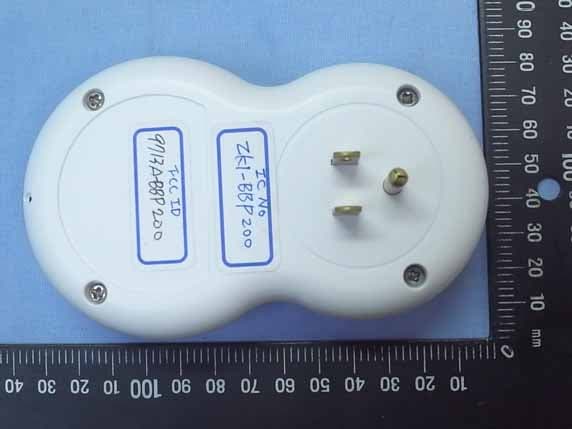
ZKI-BBP200
Nov 17, 2014BeeWi Bluetooth Smart Controlled AC Plug
Equipment Class
DTS - Digital Transmission System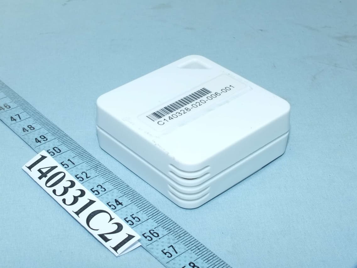
ZKI-BBW200
Jul 09, 2014BBW200 Smart Weather Sensor
Equipment Class
DTS - Digital Transmission System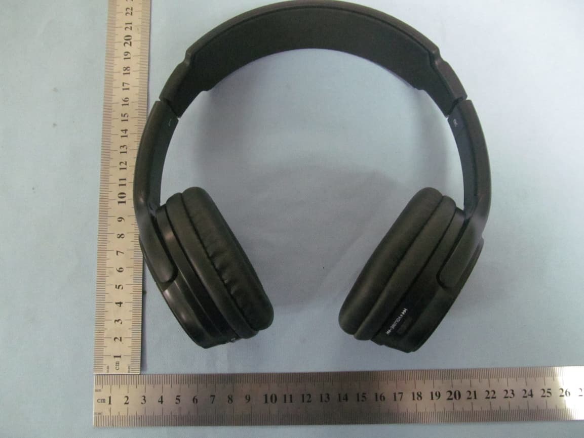
ZKI-BBH100
Dec 27, 2012Bluetooth Headset
Equipment Class
DSS - Part 15 Spread Spectrum Transmitter
ZKI-BBZ150
Dec 20, 2012Bluetooth Controlled Toy
Equipment Class
DXX - Part 15 Low Power Communication Device Transmitter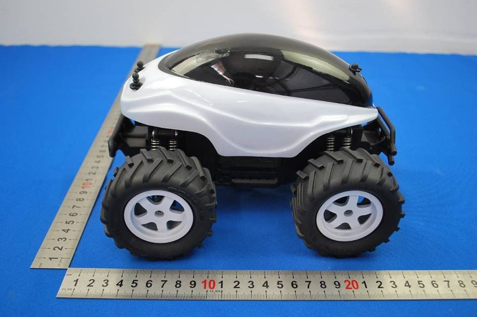
ZKI-BWZ200
Nov 18, 2012WIFI REMOTE CONTROLLED BUGGY
Equipment Class
DTS - Digital Transmission System