FCCID.CO- FCC ID Database
HomeCompaniesEquipment ClassesSearch

© 2026 FCC ID Database. All rights reserved.

AboutContactData sourced from FCC public records
  1. Home/
  2. FLARM Technology GmbH/
  3. ZKUGC625161

ZKUGC625161FHSS Transceiver

FLARM Technology GmbH
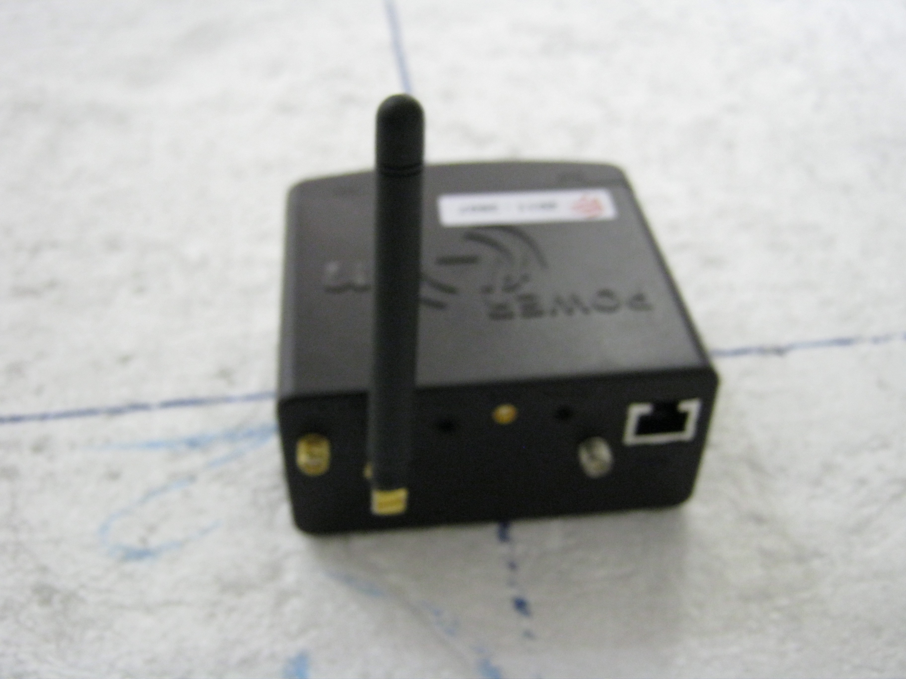
FHSS Transceiver - FCC ID ZKUGC625161 - FLARM Technology GmbH
Click to zoom

Application Details

Equipment Class
DSS - Part 15 Spread Spectrum Transmitter
Date of Grant
Jun 30, 2011
Application Purpose
Original Equipment
Date of Application
Jun 27, 2011
Equipment Note
FHSS Transceiver
Frequency Range
902.20000000 - 927.80000000
Company
FLARM Technology GmbH
Country
Switzerland

Documents & Files

Select a file to view

Users Manual

↗

Cover Letter(s)

↗
↗
↗
↗

External Photos

↗

ID Label/Location Info

↗

Internal Photos

↗

RF Exposure Info

↗

Test Report

↗

Test Setup Photos

↗

Document Text

Text extracted from the exhibit documents filed with the FCC. Open a document above to read the original.

Users Manual

PowerFLARM Manual Version 1.0 1 Manual Version 1.0 2 Contents Introduction ............................................................... 4 Installation ................................................................. 6 General Advice on Installation ......................................................... 6 Housing ..................................................................................................... 8 Connections ............................................................................................. 9 Overview .................................................................................................... 9 Power and Data Connections ........................................................... 9 Audio ..........................................................................................................10 Communications Antennas ..............................................................10 GPS-System ........................................................................................... 11 Operation with an internal Antenna ..........................................11 Operation with an external Antenna ..........................................11 FLARM®-COMMUNICATIONS ...................................................... 12 Transponder and ADS-B Reception ............................................ 12 Audio ....................................................................................................... 13 Micro SD-Card...................................................................................... 13 Insertion and Removal ......................................................................13 Power Supply ....................................................................................... 14 Power Supply using the Aircraft's own Electrical Power System .......................................................................................................14 Power Supply Using Batteries or Rechargeable Batteries14 Battery Insertion ..................................................................................15 Rechargeable internal Batteries ...................................................15 Technical Data ..................................................................................... 16 Operation ................................................................. 17 General Advice on Operation ........................................................ 17 Use ...............................................................................................................17 Compatibility .........................................................................................17 Radio Range and Reception ............................................................17 Position Determination .....................................................................18 Flight Path Calculation .....................................................................18 Data Protection ....................................................................................19 PowerFLARM Manual Version 1.0 3 Limitations ..............................................................................................19 Certification ............................................................................................19 Start-Up .................................................................................................. 19 Fault Reporting and other Information .................................... 20 Operation ............................................................................................... 20 Normal Operation .............................................................................. 21 Collision Warnings............................................................................. 22 Warning Presentation .......................................................................22 Information about Warnings .........................................................23 Settings Menu ...................................................................................... 25 Menu Diagram ......................................................................................25 Essential Settings Prior to First Flight ....................................... 26 Selection of Aircraft Type .................................................................26 ICAO Address ..........................................................................................26 Transponder ...........................................................................................26 Legal Notes ............................................................... 27 Product Guarantee ............................................................................. 27 Limitations ............................................................................................ 27 Legal Liability ...................................................................................... 28 Conformity Declaration ................................................................... 28 4 Introduction A PowerFLARM unit draws its position and movement information from an internal GPS-receiver. The position measured is rendered more accurate by an integral pressure sensor. The unit calculates the predicted flight path and transmits this information as a short, low-power digital signal burst at one-second intervals together with a unique identification code. At the same time, the unit receives similar signals from FLARM units installed in other aircraft and within radio range, or from aircraft equipped with ADS-B, Mode-C and Mode-S transponders. The PowerFLARM unit compares the signals received with its own projected flight path. An optional future additional feature will be for PowerFLARM to compare its own projected flight path with the positions of known fixed obstacles (e.g. cables, aerials, cable railways, avalanche detonation sites) held in the unit's data base. If PowerFLARM determin…

Text truncated - open the document above for the full version.

Cover Letter(s)

Page 1 of 1 Elliott TCB 684 W. Maude Ave Sunnyvale, CA, 94085 To whom it may concern: The enclosed documents constitute a formal submittal and application for Equipment Authorization for a 15.247 frequency hopping spread spectrum radio pursuant to Subpart 15 of the FCC’s rules. The device has a permanently attached antenna (refer to details in the Operational Description) and is exempt from the technical requirements for digital devices as it is used exclusively in vehicles (aircraft). Testing has been performed in accordance with the FCC’s requirements for transmitters operating under 15.247 of the rules and for receiver spurious emissions as detailed in 15.109. As the device is powered from internal batteries or the aircraft battery no AC conducted emissions tests were performed. Elliott Laboratories, as duly authorized agent prepared this submittal. A copy of the letter of our appointment as agent is included with the application. If there are any questions or if further information is needed, please contact Elliott Laboratories for assistance. Sincerely, Mark Briggs Staff Engineer

Cover Letter(s)

06/08/2011 Elliott TCB 41039 Boyce Road Fremont, CA. 94538 FCC ID: ZKUGC625161 Dear Examiner: I am writing to avoid the possibility of an inadvertent disclosure of proprietary information. The accompanying Form 731 is being filed with the commission on our behalf by Elliott Laboratories, Inc., a consulting and testing laboratory. Included as exhibits with the enclosed application are block diagrams, schematics, and a detailed description of the theory of operation of the device. It is our intention to provide Elliott TCB and the commission with a full disclosure of our product so that its merits can be evaluated. Indeed, we are pleased to provide any further information that the commission might wish to see. It is not our intention, however, to make our proprietary process a matter of public record. In view of the fact that the block diagrams, schematics, and associated theory of operation disclose the mechanism of our process, we ask that these portions (block diagrams, schematics, and theory of operation) of our application be withheld from public inspection as provided under FCC section 0.459. These documents contain details of the proprietary operation of product. These details are not readily discernible - even to technically sophisticated individuals - from our hardware and constitute trade secrets. We request therefore that these documents be segregated from the body of our evaluation report and withheld from public inspection. Thank you for your attention. Please let the undersigned know if Elliott TCB or the Commission disagrees with our position or requires further justification. Sincerely, Boris Andrea Schlapbach CFO FLARM Technology GmbH Haldenstrasse 1 CH-6340 Baar Tel +41 41 760 85 63 Fax +1 435 203 12 24 [email protected] www.flarm.com

Cover Letter(s)

Elliott TCB 41039 Boyce Road Fremont, CA. 94538 06/08/2011 Gentlemen: This is your letter of authorization to accept our appointment of Elliott Laboratories, Inc. as our Agent for Flarm Technology GmbH, Haldenstrasse 1, CH-6340 Baar, to sign applications before Elliott TCB and to make representations to you on our behalf. Elliott Laboratories, Inc. is to receive and exchange data between our company and Elliott TCB. I hereby certify on behalf of Flarm Technology GmbH, Haldenstrasse 1, CH-6340 Baar ("Applicant") that neither Applicant nor any party to the application (officers, directors, and 5% shareholders) is subject to a denial of Federal benefits that includes FCC benefits pursuant to section 5301 of the Anti-Drug Abuse Act of 1988. 21 U.S.C. 853a. Sincerely, Boris Andrea Schlapbach CFO FLARM Technology GmbH Haldenstrasse 1 CH-6340 Baar Tel +41 41 760 85 63 Fax +1 435 203 12 24 [email protected] www.flarm.com

Cover Letter(s)

1 Mark Briggs To: [email protected] Cc: David Guidotti; Christine V. Krebill Subject: RE: Comment email #1 for FCC assessment of product J83288_Flarm_ZKUGC625161 Dear Marcus, Here are the response to the questions raised during the review of the Flarm application: 1 - antenna connector(s) seems not to be of FCC approved version (reverse polarity). While the antenna connector may not be a unique connector the application documents clearly describes in the Operational Description (as referenced in the second paragraph of the Cover Letter) how the antenna is securely fastened to the rf connector such that removal of the antenna would render the device unusable: The antenna is connected to the “FLARM A” SMA socket. Thread locker glue will be applied to the screw thread of the “FLARM A” SMA socket and the mono-pole antenna will be screwed to this socket at the manufacturing site. On dispatch, the antenna is firmly connected to the device and cannot be removed or exchanged by the user. 2- what is the 3rd antenna connector (reverse polarity) being used for? The rf connectors on the device are described on page 3 of the Operational Description. • One SMA connector is used to permanently connect the transceiver antenna to the device as described in (1) above. • The second SMA connector is to provide for receive diversity on the 902-928 FLARM FHSS device • There is a MCX connector for an external GPS antenna • There is a reverse SMA for connection to a an antenna that connects to a 1090MHz receiver to receive transponder signals from other aircraft. 3- user manual does not show any RF exposure warning (information) which should be present for a 15.247 device. The rf exposure exhibit explains that the output power from the system (10mW) is below the 60/f threshold and so is suitable for use in portable and mobile rf exposure conditions. We did not consider that a warning statement would be required for this low power device. Note that the 10mW output power is peak and does not include the 1% duty cycle for 10ms transmit time in a 1second period. The average power would be 0.1mW. Please advise if additional information is required to complete your review. A copy of this email will be placed in the TCB folder as a cover letter if you need to include these responses with the submittal documents. Regards, Mark Briggs Elliott-NTS

RF Exposure Info

EMC Test Data Client: Contact: Standard: Test Specific Details General Test Configuration N/A (see note) - The output power from the device is 10mW, which is below the threshold of 60/f(GHz) and therefore considered to comply with rf exposure requirements for both portable and mobile exposure conditions. The 60/f threshold at 900MHz is 65mW. Modifications Made During Testing No modifications were made to the EUT during testing Deviations From The Standard No deviations were made from the requirements of the standard. Calculation uses the free space transmission formula: S = (PG)/(4 πd 2 ) Where: S is power density (W/m 2 ), P is output power (W), G is antenna gain relative to isotropic, d is separation distance from the transmitting antenna (m). Summary of Results Device complies with Power Density requirements at 20cm separation: If not, required separation distance (in cm): Test Engineer: Mark Briggs Maximum Permissible Exposure Objective: The objective of this test session is to perform final qualification testing of the EUT with respect to the specification listed above. Date of Test: 6/14/2011 Urs Rothacher FCC Part 15.247 (FHSS)Class:N/A FlarmJob Number: J83288 Model: PowerFLARM Portable (Rev A) T-Log Number: T83437 Account Manager: Christine Krebill T83437RF ExposurePage 1 of 1

Test Report

File: R83521 Page 1 of 20 EMC Test Report Application for Grant of Equipment Authorization FCC Part 15 Subpart C Model: PowerFLARM Portable (Rev A) IC CERTIFICATION #: N/A FCC ID: ZKUGC625161 APPLICANT: Flarm GmbH Haldenstr.1 CH-6340 Baar, Switzerland TEST SITE(S): Elliott Laboratories 41039 Boyce Road. Fremont, CA. 94538-2435 IC SITE REGISTRATION #: 2845B-3 & 2845B-4 REPORT DATE: June 17, 2011 FINAL TEST DATES: June 2 and June 8, 2011 AUTHORIZED SIGNATORY: ______________________________ Mark Briggs Staff Engineer Elliott Laboratories Elliott Laboratories is accredited by the A2LA, certificate number 2016-01, to perform the test(s) listed in this report, except where noted otherwise. This report shall not be reproduced, except in its entirety, without the written approval of Elliott Laboratories Elliott Laboratories -- EMC Department Test Report Report Date: June 17, 2011 File: R83521 Page 2 of 20 REVISION HISTORY Rev# Date Comments Modified By - 06-17-2011 First Release Elliott Laboratories -- EMC Department Test Report Report Date: June 17, 2011 File: R83521 Page 3 of 20 TABLE OF CONTENTS REVISION HISTORY .............................................................................................................................................. 2 TABLE OF CONTENTS .......................................................................................................................................... 3 SCOPE........................................................................................................................................................................ 4 OBJECTIVE .............................................................................................................................................................. 4 STATEMENT OF COMPLIANCE......................................................................................................................... 5 DEVIATIONS FROM THE STANDARDS ............................................................................................................ 5 TEST RESULTS SUMMARY ................................................................................................................................. 6 FREQUENCY HOPPING SPREAD SPECTRUM (902 – 928 MHZ, 50 CHANNELS OR MORE) ........................ 6 GENERAL REQUIREMENTS APPLICABLE TO ALL BANDS........................................................................ 6 MEASUREMENT UNCERTAINTIES..................................................................................................................7 EQUIPMENT UNDER TEST (EUT) DETAILS .................................................................................................... 8 GENERAL.............................................................................................................................................................. 8 ANTENNA SYSTEM ............................................................................................................................................ 8 ENCLOSURE......................................................................................................................................................... 8 MODIFICATIONS................................................................................................................................................. 8 SUPPORT EQUIPMENT....................................................................................................................................... 8 EUT OPERATION ................................................................................................................................................. 8 TEST SITE................................................................................................................................................................. 9 GENERAL INFORMATION ................................................................................................................................. 9 CONDUCTED EMISSIONS CONSIDERATIONS .............................................................................................. 9 RADIATED EMISSIONS CONSIDERATIONS .................................................................................................. 9 MEASUREMENT INSTRUMENTATION .......................................................................................................... 10 RECEIVER SYSTEM .......................................................................................................................................... 10 INSTRUMENT CONTROL COMPUTER .......................................................................................................... 10 LINE IMPEDANCE STABILIZATION NETWORK (LISN)............................................................................. 10 FILTERS/ATTENUATORS ................................................................................................................................ 11 ANTENNAS......................................................................................................................................................... 11 ANTENNA MAST AND EQUIPMENT TURNTABLE ..................................................................................... 11 INSTRUMENT CALIBRATION......................................................................................................................... 11 TEST PROCEDURES ............................................................................................................................................ 12 EUT AND CABLE PLACEMENT ......................................................................................................................12 CONDUCTED EMISSIONS................................................................................................................................ 12 RADIATED EMISSIONS .......................................................................................................…

Text truncated - open the document above for the full version.

Contact Information

Applicant

Boris Schlapbach
[email protected]0041794728252Fax: 0041417608565

Technical Contact

Elliott Laboratories LLCMark Briggs
[email protected]5105783500

41039 Boyce Road · Fremont · United States

Test Firm

Elliott Laboratories LLCDavid Bare
[email protected]408-245-7800Fax: 408-245-3499

Technical Specifications

#Rule PartsFrequency RangePower Output
115C902.2 MHz - 927.8 MHz10.00 mW
Confidentiality
Long Term
Grant Notes
Power listed is conducted. The antenna(s) used with this transmitter must not transmit simultaneously with any other antenna or transmitter except in accordance with FCC multi- transmitter product procedures.

Other Applications from FLARM Technology GmbH
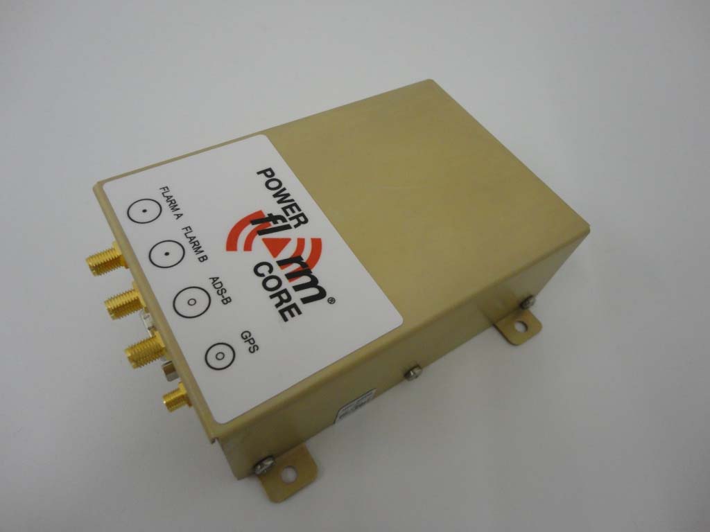
PowerFLARM BRICK - FCC ID ZKUGC625162 - FLARM Technology GmbH
ZKUGC625162

PowerFLARM BRICK

Jul 26, 2012

Equipment Class

DSS - Part 15 Spread Spectrum Transmitter