FCCID.CO- FCC ID Database
HomeCompaniesEquipment ClassesSearch

© 2026 FCC ID Database. All rights reserved.

AboutContactData sourced from FCC public records
  1. Home/
  2. FLARM Technology GmbH/
  3. ZKUGC625162

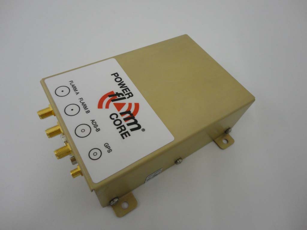
ZKUGC625162PowerFLARM BRICK

FLARM Technology GmbH
PowerFLARM BRICK - FCC ID ZKUGC625162 - FLARM Technology GmbH
Click to zoom

Application Details

Equipment Class
DSS - Part 15 Spread Spectrum Transmitter
Date of Grant
Jul 26, 2012
Application Purpose
Original Equipment
Date of Application
Jul 25, 2012
Equipment Note
PowerFLARM BRICK
Frequency Range
902.20000000 - 927.80000000
Company
FLARM Technology GmbH
Country
Switzerland

Documents & Files

Select a file to view
Users Manual

↗

Cover Letter(s)

↗
↗
↗

External Photos

↗

ID Label/Location Info

↗

Internal Photos

↗

RF Exposure Info

↗

Test Report

↗

Test Setup Photos

↗

Document Text

Text extracted from the exhibit documents filed with the FCC. Open a document above to read the original.

Users Manual

PowerFLARM BRICK-Manual 2.20 US 1 PowerFLARM BRICK Manual Version 2.20 US June 27 2012 PowerFLARM BRICK-Manual 2.20 US 2 Contents Parts List ......................................................................... 3 Working Principle ........................................................... 3 Installation ..................................................................... 4 General Advice on Installation .............................................................. 4 Housing .......................................................................................................... 5 Connections .................................................................................................. 6 Overview .......................................................................................................... 6 RJ45: Power and Data Connections ..................................................... 6 DSub9: Power and Data Connections ................................................. 7 USB ................................................................................................................... 9 Power Supply ............................................................................................ 10 LED ................................................................................................................ 10 Configuration ............................................................................................ 11 Example configuration file (FLARMCFG.TXT) ............................. 11 Essential Settings Prior to First Flight ............................................ 12 Selection of Aircraft Type ...................................................................... 12 Transponder ................................................................................................ 12 ICAO Address ............................................................................................... 12 Legal Notes ................................................................... 13 Product Warranty ................................................................................... 13 Limitations ................................................................................................. 13 FLARM® Radio Communication....................................................... 14 Legal Liability ........................................................................................... 14 Conformity Declaration ........................................................................ 15 RF Radiation Hazard WarningFehler! Textmarke nicht definiert. Maximum Antenna Gain ....................................................................... 16 Industry Canada Notice and Marking ............................................. 17 Appendix A: Mechanical Drawings ............................... 18 BRICK ........................................................................................................... 18 FLARM and PCAS/ADS-B remote antenna ................................... 18 PowerFLARM BRICK-Manual 2.20 US 3 Parts List Your PowerFLARM™ BRICK™ contains the following parts:  1 BRICK, a golden metallic box  1 FLARM radio antenna with 6.5ft cable and RP-SMA connector  1 GPS antenna with magnetic socket and 15ft cable  1 PCAS/ADS-B antenna with 6.5ft cable and SMA connector  1 power / data cable with 3ft cable and an open-cut end PowerFLARM BRICK does not have an integrated display, but connects to a wide range of display interfaces, PDA’s, on-board flight computers, moving map applications and MFD. The typical installation connects to a Remote PowerFLARM Display. Suitable cables providing power and data are delivered with the display. Working Principle Based on GPS and the pressure sensor, PowerFLARM predicts your short-term future flight path and continuously transmits this to nearby aircraft by a digital radio message. FLARM-compatible systems in nearby aircraft receive your radio message and send you a similar message with their data. With such you not only know the whereabouts of aircraft around you, your BRICK is also able to calculate conflicting flight patterns and alert you of such traffic on a suited display (FLARM functionality). PowerFLARM also receives data from aircraft with transponders (Mode C and S) or ADS-B OUT (1090ES), and uses these messages for traffic information and alerts (PCAS functionality). The effective range depends very much upon the position in which antennas are fitted and facilitates a warning, visual identification, and appropriate action by the pilots in both aircraft. FLARM-warnings are issued in accordance with the time remaining to a possible collision, not the geometric distance between the aircraft. The first warning is typically issued between 19 and 25 seconds in advance to the calculated possible collision with aircraft or obstacle (time to impact); the second is issued 14 to 18 seconds in advance, and the third 6 to 8 seconds in advance. Warnings are PowerFLARM BRICK-Manual 2.20 US 4 sustained as long as the threat remains as calculated. Depending upon the prediction, the threat may be downgraded or deleted. Warnings are selective, i.e. they are only issued if the calculation detects a high probability of a collision in the immediate future. In the future and with costs, PowerFLARM BRICK will also be able to alert you of known fixed obstacles stored in the unit's data base (optional functionality at cost), and store your entire flight in the common IGC-format for analysis and documentation. Installation General Advice on Installation Installation and operation is on a non-interference and non-hazard basis, and may not endanger the safe operation of certified equipment that is either necessary or required by regulation for safe flight. Installation must comply with official requirements. BRICK must not obstruct the pilot in his operation of the aircraft (including emergencies); in particular at all times it must not obstruct hi…

Text truncated - open the document above for the full version.

Cover Letter(s)

Page 1 of 1 Elliott TCB 41039 Boyce Road Fremont, CA, 94538 To whom it may concern: The enclosed documents constitute a formal submittal and application for Equipment Authorization for a 900 MHz frequency hopping spread spectrum radio pursuant to the following rules: Subpart C of Part 15 of FCC Rules (CFR 47), Intentional Radiators RSS-Gen Issue 3, December 2010, “General Requirements and Information for the Certification of Radiocommunication Equipment” RSS-210, Issue 8, December 2010, “Low-power Licence-exempt Radiocommunication Devices (All Frequency Bands): Category I Equipment” The device is exempt from the technical requirements for digital devices as it is used exclusively in vehicles (aircraft). Testing has been performed in accordance with FCC and Industry Canada requirements for transmitters operating under FCC 154.247 and RSS-210, Annex 8 and for receiver spurious emissions as detailed in FCC 15.109 and RSS-GEN. As the device is powered from the aircraft battery no AC conducted emissions tests were performed. Elliott Laboratories, as duly authorized agent prepared this submittal. A copy of the letter of our appointment as agent is included with the application. If there are any questions or if further information is needed, please contact Elliott Laboratories for assistance. Sincerely, Mark Hill Staff Engineer

Cover Letter(s)

Elliott TCB 41039 Boyce Road Fremont, CA. 94538 06/08/2011 Gentlemen: This is your letter of authorization to accept our appointment of Elliott Laboratories, Inc. as our Agent for Flarm Technology GmbH, Haldenstrasse 1, CH-6340 Baar, to sign applications before Elliott TCB and to make representations to you on our behalf. Elliott Laboratories, Inc. is to receive and exchange data between our company and Elliott TCB. I hereby certify on behalf of Flarm Technology GmbH, Haldenstrasse 1, CH-6340 Baar ("Applicant") that neither Applicant nor any party to the application (officers, directors, and 5% shareholders) is subject to a denial of Federal benefits that includes FCC benefits pursuant to section 5301 of the Anti-Drug Abuse Act of 1988. 21 U.S.C. 853a. Sincerely, Boris Andrea Schlapbach CFO FLARM Technology GmbH Haldenstrasse 1 CH-6340 Baar Tel +41 41 760 85 63 Fax +1 435 203 12 24 [email protected] www.flarm.com

Cover Letter(s)

June 20, 2012 Elliott TCB 41039 Boyce Road Fremont, CA. 94538 FCC ID: ZKUGC625162 Dear Examiner: I am writing to avoid the possibility of an inadvertent disclosure of proprietary information. The accompanying Form 731 is being filed with the commission on our behalf by Elliott Laboratories, Inc., a consulting and testing laboratory. Included as exhibits with the enclosed application are block diagrams, schematics, and a detailed description of the theory of operation of the device. It is our intention to provide Elliott TCB and the commission with a full disclosure of our product so that its merits can be evaluated. Indeed, we are pleased to provide any further information that the commission might wish to see. It is not our intention, however, to make our proprietary process a matter of public record. In view of the fact that the block diagrams, schematics, and associated theory of operation disclose the mechanism of our process, we ask that these portions (block diagrams, schematics, and theory of operation) of our application be withheld from public inspection as provided under FCC section 0.459. These documents contain details of the proprietary operation of product. These details are not readily discernible - even to technically sophisticated individuals - from our hardware and constitute trade secrets. We request therefore that these documents be segregated from the body of our evaluation report and withheld from public inspection. Thank you for your attention. Please let the undersigned know if Elliott TCB or the Commission disagrees with our position or requires further justification. Sincerely, Boris Andrea Schlapbach CFO FLARM Technology GmbH Lindenstrasse 4 CH-6340 Baar Tel +41 41 760 85 63 Fax +1 435 203 12 24 [email protected] www.flarm.com

External Photos

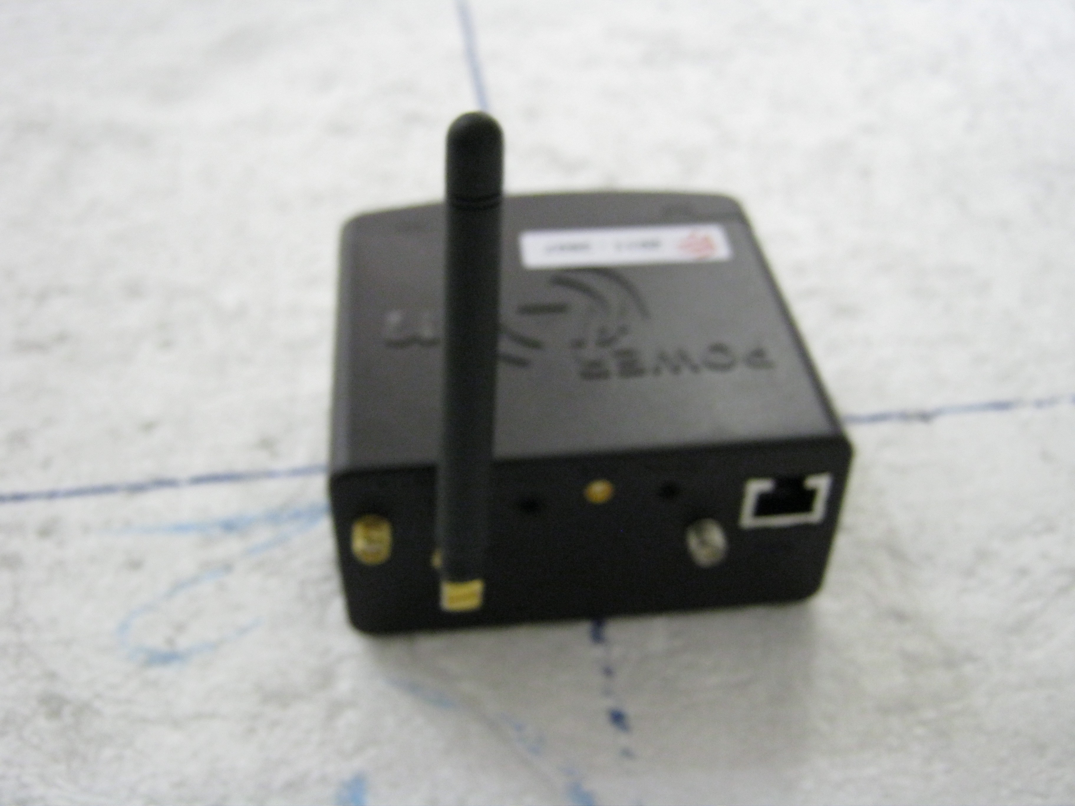
EUT Top EUT Diagonal EUT Diagonal 2 EUT Side EUT Connectors

Internal Photos

EUT Build Up 1 EUT Build Up 2 Coreboard – Top Coreboard – Bottom Baseboard – Top Baseboard – Bottom ADS‐B Module – Top with Shields ADS‐B Module – Top without Shields ADS‐B Module – Bottom

RF Exposure Info

EMC Test Data Client: Contact: Standard: Test Specific Details General Test Configuration N/A (see note) Calculation uses the free space transmission formula: S = (PG)/(4 πd 2 ) Where: S is power density (W/m 2 ), P is output power (W), G is antenna gain relative to isotropic, d is separation distance from the transmitting antenna (m). Summary of Results Device complies with Power Density requirements at 20cm separation: Maximum Permissible Exposure Objective: The objective of this test session is to perform final qualification testing of the EUT with respect to the specification listed above. Date of Test: 6/12/2012 Test Engineer: Mark Hill Urs Rothacher FCC Part 15.247 (FHSS)Class: N/A FlarmJob Number: J87484 Model: PowerFLARM Brick T-Log Number: T87614 Account Manager: Christine Krebill (see note) - No deviations were made from the requirements of the standard. The output power from the device is 36.3mW, which is below the threshold of 60/f(GHz) and therefore considered to comply with rf exposure requirements for both portable and mobile exposure conditions. The 60/f threshold at 900MHz is 65mW. If not, required separation distance (in cm): Modifications Made During Testing No modifications were made to the EUT during testing Deviations From The Standard 20cm separation: T87614.xlsRF ExposurePage 1 of 1

Test Report

File: R87922 Page 1 EMC Test Report Application for Grant of Equipment Authorization Industry Canada RSS-Gen Issue 3 / RSS 210 Issue 8 FCC Part 15 Subpart C Model: PowerFLARM Brick IC CERTIFICATION #: 10154A-FLAPFC10 FCC ID: ZKUGC625162 APPLICANT: Flarm GmbH Haldenstr. 1 CH-6340 Baar, Switzerland TEST SITE(S): NTS Silicon Valley 41039 Boyce Road. Fremont, CA. 94538-2435 IC SITE REGISTRATION #: 2845B-4, 2845B-5, 2845B-7 REPORT DATE: July 6, 2012 FINAL TEST DATES: May 14, 17, 22 and 25, 2012 TOTAL NUMBER OF PAGES: 50 PROGRAM MGR / QUALITY ASSURANCE DELEGATE / TECHNICAL REVIEWER: FINAL REPORT PREPARER: ______________________________ ______________________________ Mark E Hill David Guidotti Staff Engineer Senior Technical Writer NTS Silicon Valley is accredited by the A2LA, certificate number 0214.26, to perform the test(s) listed in this report, except where noted otherwise. This report and the information contained herein represent the results of testing test articles identified and selected by the client performed to specifications and/or procedures selected by the client. National Technical Systems (NTS) makes no representations, expressed or implied, that such testing is adequate (or inadequate) to demonstrate efficiency, performance, reliability, or any other characteristic of the articles being tested, or similar products. This report should not be relied upon as an endorsement or certification by NTS of the equipment tested, nor does it represent any statement whatsoever as to its merchantability or fitness of the test article, or similar products, for a particular purpose. This report shall not be reproduced except in full NTS Silicon Valley -- EMC Department Test Report Report Date: July 6, 2012 File: R87922 Page 2 REVISION HISTORY Rev# Date Comments Modified By - 07-06-2012 First release NTS Silicon Valley -- EMC Department Test Report Report Date: July 6, 2012 File: R87922 Page 3 TABLE OF CONTENTS REVISION HISTORY ................................................................................................................................................ 2 TABLE OF CONTENTS ............................................................................................................................................ 3 SCOPE .......................................................................................................................................................................... 4 OBJECTIVE ................................................................................................................................................................ 4 STATEMENT OF COMPLIANCE ........................................................................................................................... 5 DEVIATIONS FROM THE STANDARDS .............................................................................................................. 5 TEST RESULTS SUMMARY ................................................................................................................................... 6 FREQUENCY HOPPING SPREAD SPECTRUM (902 – 928 MHZ, 50 CHANNELS OR MORE) .......................... 6 GENERAL REQUIREMENTS APPLICABLE TO ALL BANDS .......................................................................... 6 MEASUREMENT UNCERTAINTIES .................................................................................................................... 7 EQUIPMENT UNDER TEST (EUT) DETAILS ...................................................................................................... 8 GENERAL ................................................................................................................................................................ 8 ANTENNA SYSTEM .............................................................................................................................................. 8 ENCLOSURE ........................................................................................................................................................... 8 MODIFICATIONS ................................................................................................................................................... 8 SUPPORT EQUIPMENT ......................................................................................................................................... 8 EUT INTERFACE PORTS ...................................................................................................................................... 9 EUT OPERATION ................................................................................................................................................... 9 TEST SITE ................................................................................................................................................................. 10 GENERAL INFORMATION ................................................................................................................................. 10 CONDUCTED EMISSIONS CONSIDERATIONS .............................................................................................. 10 RADIATED EMISSIONS CONSIDERATIONS .................................................................................................. 10 MEASUREMENT INSTRUMENTATION ............................................................................................................ 11 RECEIVER SYSTEM ............................................................................................................................................ 11 INSTRUMENT CONTROL COMPUTER ............................................................................................................ 11 LINE IMPEDANCE STABILIZATION NETWORK (LISN) ............................................................................... 11 FILTERS/ATTENUATORS .......................................................................................................…

Text truncated - open the document above for the full version.

Contact Information

Applicant

Boris Schlapbach
[email protected]0041794728252Fax: 0041417608565

Technical Contact

Elliott Laboratories - An NTS CompanyMark Hill
[email protected]

Fremont · United States

Test Firm

Elliott Laboratories LLCDavid Bare
[email protected]408-245-7800Fax: 408-245-3499

Technical Specifications

#Rule PartsFrequency RangePower Output
115C902.2 MHz - 927.8 MHz20.00 mW
Confidentiality
Long Term
Grant Notes
Power output listed is conducted. The antenna(s) used for this transmitter must not be co-located or operating in conjunction with any other antenna or transmitter.

Other Applications from FLARM Technology GmbH

FHSS Transceiver - FCC ID ZKUGC625161 - FLARM Technology GmbH
ZKUGC625161

FHSS Transceiver

Jun 30, 2011

Equipment Class

DSS - Part 15 Spread Spectrum Transmitter