ZMNVD1USADisplay - 2 Digits
OPEN DATA SRL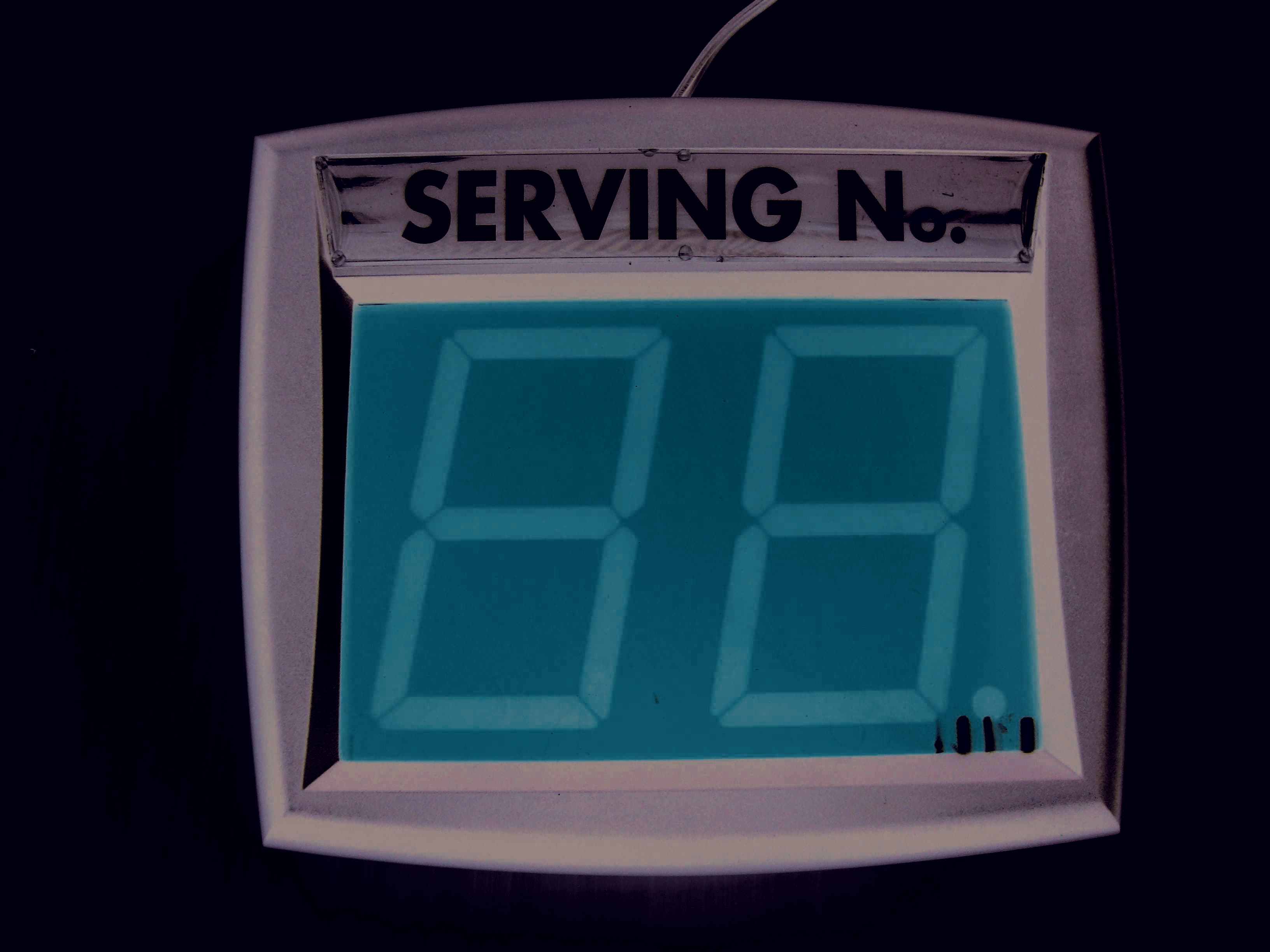
Click to zoom
Application Details
- Equipment Class
- DSR - Part 15 Remote Control/Security Device Transceiver
- Date of Grant
- Sep 12, 2012
- Application Purpose
- Original Equipment
- Date of Application
- Sep 11, 2012
- Equipment Note
- Display - 2 Digits
- Frequency Range
- 433.92000000 - 433.92000000
- Company
- OPEN DATA SRL
- Country
- Italy
Documents & Files
Document Text
Text extracted from the exhibit documents filed with the FCC. Open a document above to read the original.
Users Manual
INSTRUCTION ISTRUZIONI INSTRUCCIONES INSTRUCTIONS HANDLEIDING ADVERTENCIAS: 1) SEGUIR LAS INSTRUCCIONES INDICADAS EN EL MANUAL 2) LA INSTALACIÓN TIENE CHE SER EFECTUADA POR EL PERSONAL TÉCNICO SEGÚN LAS ISTRUCCIONES 3) NO MODIFICAR LOS APARATOS 4) NO UTILIZAR EL PRODUCTO SI PRESENTA DESPERFECTOS INSTALACION DE LA PLANTALLA TODA LA FASE DE MONTAJE SE REALIZA CON LA PLANTALLA DESCONECTADA DE LA RED ELECTRICA • ATORNILLAR A LA PARED LA CHAPA PARA FIJARLA • ATORNILLAR LA CONTRACHAPA SOBRE LA CHAPA FIJADA A LA PARED • INTRODUCIR EL ESTRIBO DE SUJECIÓN • ORIENTAR LA PANTALLA EN LA POSICIÓN DESEADA Y FIJARLA • INTRODUCIR EL ESTRIBO DE SUJECIÓN EN LA GUIA DE LA CHAPA SITUADO DE TRÁS DE LA PANTALLA • ORIENTAR LA PANTALLA EN LA POSICIÓN DESEADA Y AJUSTAR LA CHAPA • CONECTAR LA PANTALLA A UNA TOMA DE CORRIENTE ELECTRICA;EL CIRCUITO ESTA PROTEGIDO POR UN FUSIBLE DE 800 mA EFECTUAR EL CAMBIO POR PERSONAL AUTORIZADO • LA PANTALLA VD1 TIENE QUE INSTALARSE LEJOS DE FUENTES QUE TRANSMITAN DISTURBIOS ELECTROMAGNETICOS (NEON, MONITOR, ETC.) QUE PUEDAN REDUCIR EL CAMPO DE FUNCIONAMIENTO DISPLAY INSTALLATION INSTALLAZIONE DEL VISORE ISTALACIÓN DE LA PANTALLA INSTALLATION DU TABLEAU MURAL INSTALLEREN VAN HET NUMMERBORD AVVERTENZE: 1) SEGUIRE LE ISTRUZIONI RIPORTATE NEL MANUALE 2) L’INSTALLAZIONE DEVE ESSERE EFFETTUATA DA PERSONALE ESPERTO 3) NON MODIFICARE LE APPARECCHIATURE 4) NON UTILIZZARE IL PRODOTTO SE PRESENTA DANNEGGIAMENTI INSTALLAZIONE DEL VISORE. TUTTA LA FASE DEL MONTAGGIO VA FATTA CON IL VISORE SCOLLEGATO DALLA RETE ELETTRICA • AVVITARE A PARETE LA PIASTRA DI FISSAGGIO • AVVITARE LA CONTROPIASTRA SULLA PIASTRA FISSATA A PARETE • INSERIRE LA STAFFA DI SOSTEGNO • ORIENTARE LA STAFFA NELLA POSIZIONE DESIDERATA E FISSARLA • INSERIRE LA STAFFA DI SOSTEGNO NELLA GUIDA DELLA PIASTRA POSTA NEL RETRO DEL VISORE • ORIENTARE IL VISORE NELLA POSIZIONE DESIDERATA E STRINGERE LA PIASTRA • COLLEGARE IL VISORE AD UNA PRESA DI CORRENTE ELETTRICA CHE DEVE TROVARSI VICINO ED ESSERE FACILMENTE ACCESSIBILE, IL CIRCUITO È PROTETTO DA UN FUSIBILE RAPIDO F 800 mA. LA SOSTITUZIONE VA EFFETTUATA DA PERSONALE AUTORIZZATO • IL VISORE VD1 DEVE ESSERE INSTALLATO LONTANO DA FONTI CHE EMETTONO DISTURBI ELETTROMAGNE TICI (NEON, MONITOR, ETC.), CHE POSSONO RIDURRE IL CAMPO DI FUNZIONAMENTO VD1 DATA SHEET SCHEDA TECNICA VD1 CARACTERÍSTICAS TÉCNICAS VDI VD1 FICHE TECHNIQUE VD1 TECHNISCHE FICHE INSTRUCTIONS: 1) FOLLOW THE INSTRUCTIONS AS INDICATED IN THE MANUAL BOOK 2) THE INSTALLATION MUST BE DONE BY TECHNICAL PERSONNEL ONLY, ACCORDING TO THE LAW IN FORCE 3) DO NOT MODIFY THE EQUIPMENTS 4) DO NOT USE THE PRODUCTS IN CASE IT PRE- SEN5T ANY ALTERATION HOW TO INSTALL THE DISPLAY DURING THE INSTALLATION PROCEDURE THE DISPLAY MUST BE DISCONNECTED • SCREW THE ANCHOR PLATE ON TO THE WALL • SCREW THE SECOND PLATE ON THE ANCHOR PLATE ON THE WALL • INSERT HOLDING FLASK • DIRECT IT AS REQUIRED AND FIX • INSERT THE HOLDING FLASK INTO THE FLASK GUIDE PLACED ON THE BACK OF DISPLAY • DIRECT TO DISPLAY INTO DESIRED POSITION AND TIGHTEN THE FLASK • PLUG THE DISPLAY INTO THE SOCKET WHICH MUST BE PLACED NEARBY, EASY OF ACCESS. THE CIRCUIT IS PROTECTED BY A F 800mA QUICK-BREAK FUSE • THE DISPLAY MUST BE INSTALLED AAY FROM SOURCES TRASMITTING ELECTROMAGNETIC DISTURBANCE (NEON, MONITORS, ETC) THAT CAN REDUCE THE OPERATION FIELD DISPLAY INSTRUCTIONS: 1) SUIVRE LES INSTRUCTIONS DU MANUEL 2) L’INSTALLATION DOIT ÊTRE FAITE PAR DU PERSONNEL TECHNIQUE SELON LES DISPOSITIONS EN VIGUEUR 3) NE PAS MODIFIER LES APPAREILS 4) NE PAS UTILISER LE PRODUIT S’IL PRÉSENTE DES DOMMAGES COMMENT INSTALLER LE TABLEAU MURAL DURANT L’INSTALLATION LE TABLEAU MURAL DOIT ETRE DEBRANCHE DU COURANT • VISSER LA PLAQUETTE DE FIXATION AU MUR • VISSER LA CONTRE-PLAQUETTE SUR LA PLAQUETTE DÉJÀ FIXÉE AU MUR • IINSÉRER LA PIÈCE DE SOUTIEN • ORIENTER LA PIÈCE DANS LA POSITION DÉSIRÉE ET LA FIXER • INSÉRER LA PIÈCE DE SOUTIEN DANS LE GUIDE DE LA PLAQUETTE SITUÉ À L’ARRIÈRE DU TABLEAU MURAL • ORIENTER LE TABLEAU MURAL DANS LA POSITION DÉSIRÉE ET SERRER LA PLAQUETTE • BRANCHER LE TABLEAU MURAL À UNE PRISE DE COURANT À PROXIMITÉ ET QUI EST FACILE D’ACCÈS. LE CIRCUIT EST PROTÉGÉ PAR UN FUSIBLE F800MA. LE REMPLACEMENT NE PEUT ÊTRE FAIT QUE PAR DU PERSONNEL AUTORISÉ • LE TABLEAU MURAL DOIT ÊTRE INSTALLÉ À L’ÉCART DE TOUTE SOURCE ÉMETTANT DES PARASITES ÉLECTROMAGNÉTIQUES (NÉON, MONITOR, ETC....) QUI PEUVENT RÉDUIRE LE CHAMPS DE FONCTIONNEMENT INSTRUCTIES: 1) VOLG DE INSTRUCTIES VAN DE HANDLEIDING 2) DE INSTALLATIE DIENT ENKEL TE GEBEUREN DOOR TECHNISCH PERSONEEL, VOLGENS DE GELDENDE WETTELIJKE BEPALINGEN 3) WIJZIG NIETS AAN DE APPARATUUR 4) INDIEN BESCHADIGT, HET PRODUCT NIET GEBRUIKEN INSTALLATIE VAN HET NUMMERBORD HET NUMMERBORD MOET LOSGEKOPPELD ZIJN VAN DE STROOM TIJDENS DE INSTALLATIE • SCHROEF HET BEVESTIGINGSPLAATJE IN DE MUUR • SCHROEF HET TWEEDE PLAATJE OP HET REEDS VERANKERDE PLAATJE • BEUGEL ERIN SCHUIVEN • BEUGEL IN DE GEWENSTE RICHTING DRAAIEN EN VASTZETTEN • BEUGEL IN HET PLAATJE OP DE ACHTERZIJDE VAN HET NUMMERBORD SCHUIVEN • NUMMERBORD IN DE GEWENSTE RICHTING DRAAIEN EN HET PLAATJE VASTZETTEN • STEKKER IN HET STOPCONTACT STEKEN. STOPCONTACT MOET DICHTBIJ EN GEMAKKELIJK BEREIKBAAR ZIJN. HET CIRCUIT WORDT BEVEILIGD DOOR EEN DOORSLAGSCHAKELAAR VAN F800MA. VERVANGING MAG ENKEL UITGEVOERD WORDEN DOOR BEVOEGD PERSONEEL • HET NUMMERBORD MOET GEMONTEERD WORDEN OP VEILIGE AFSTAND VAN ELEKTROMAGNETISCHE BRONNEN (NEON, MONITORS, ENZ...) DIE HET BEREIK KUNNEN VERKLEINEN • 2 DIGIT 120MM EIGHT, EACH COMPOSED WITH 28 HIGH EFFICIEN- CY RED LED • OPERATIVE TEMPERATURE: +5° / +45° • POWER CONSUMPTION: 5W • NON-VOLATILE MEMORY TO STORE THE CURRENT TURN AND THE OTHER PARAMETERS • MULTITONAL BUZZER WITH REMOTE ADJUSTABLE LEVEL • REMOTE SETTING OF THE WORKING CODE (1-8) CAN OPERATE AS MASTER OR SLAVE (FACTORY PRESETTED AS MASTER) • WORKING FREQUENCY: DUAL BAND 433.92 - 868 MHZ • POWER SUPPLY: 220VAC (110VAC FOR US COUNTRIES), 2 MT POWER CORD • WORKING RANGE (BETWEEN VD1 MASTER AND VD1 SLAVES) 1-30M • 2 D…
Text truncated - open the document above for the full version.
Block Diagram
Cod. Fisc./Part. IVA 01681620603 Codice CEE: ITO 1681620603 Cap. Soc. € 49.920,00 int. v ers. C.C.I.A.A. 94541 Reg. Soc. N. 61 20/89 Trib. FR Pos. Comm. Estero FR 002034 Via Anticolana Km 0.300 03012 ANAGNI (FR) Tel. 0775 77681 Fax 0775 774018 www.openitaly.com [email protected] VD1USA BLOCK DIAGRAM
Block Diagram
1 2710 15 Narrow Bandwidth Super Regenerative Radio Receiver - Laser Trimmed Inductor RR10-XXX The RR10-XXX is a super regenerative data receiver. Sensitivity typically exceedes -100dBm (2.2uVrms) when matched to 50 ohm. Narrow Bandwidth: -3dB+/-1.5MHz -30dB+/- 5MHz -50dB+/- 7MHz The frequency accuracy is very high thanks to laser trimming process. PATENTED. General description Applications CHARACTERISTICSMINTYPMAX UNIT Electrical Characteristics V RF V AF V ol V oh I S In BLOCK DIAGRAM TYPICAL APPLICATION Mechanical Dimensions Pin Description 1RF +V9NC 2RF GND10AF +V 3IN11AF GND 4NC12AF +V 5NC13Test Point 6NC14OUT 7RF GND15AF +V 8NC CC CC CC CC RF Supply Voltage AF Supply Voltage Supply Current F W B W T OP Working Frequency Tuning Tolerance -3dB Bandwidth RF Sensitivity (100% AM) Level of Emitted Spectrum Low-Level Output Voltage High-Level Output Voltage Max Data Rate Operating Temperature Range XXX:custom-specified working frequency (200 ÷ 450 MHz) Standard European and U.S. frequencies (315MHz, 418MHz, 433.92MHz) are readly available from stock. · · · · Home security systems Car Alarm systems Remote gate controls Sensor reporting 4.5 4.5 200450 3.6 0.6 -65-60 5.5 5.5 5 5 1.5 VDC VDC V V 1.2 +/-0.2+/-0.5 +/-1.5+/-2 4.8 -100-102 mA dBm dBm MHz MHz MHz Kbit/s -25+80°C Radio Receiver LP Filter Quench Oscillator Comparator OUT GND RFAF Point AF V RF V AF GND Test GND DECODER IN OUT +5V AERIAL Pre-AmpOscillator RFRF AM Ampli I-ETS 300-220 Compliance 38.1mm 12.7mm 2.54mm 1 2710 15 Components Side 1mm RR10-XXX Ta = 25°C unless otherwise specified Telecontrolli Srl has an on going policy to improve the performance and reliability of their products; we therefore reserve the right to make changes without notice. The information contained in our data sheets is believed to be accurate, however we do not assume any liability arising from the application or use of any product or circuit. SALES OFFICE sales @ telecontrolli.com HEAD OFFICE & PLANT Via Nazionale delle Puglie, 177 80026 CASORIA (NA), Italy Tel: +39 081 7599033 Fax: +39 081 7596494 Web Site: www.telecontrolli.com 1 2710 15 Narrow Bandwidth Super Regenerative Radio Receiver - Laser Trimmed Inductor RR10-XXX The RR10-XXX is a super regenerative data receiver. Sensitivity typically exceedes -100dBm (2.2uVrms) when matched to 50 ohm. Narrow Bandwidth: -3dB+/-1.5MHz -30dB+/- 5MHz -50dB+/- 7MHz The frequency accuracy is very high thanks to laser trimming process. PATENTED. General description Applications CHARACTERISTICSMINTYPMAX UNIT Electrical Characteristics V RF V AF V ol V oh I S In BLOCK DIAGRAM TYPICAL APPLICATION Mechanical Dimensions Pin Description 1RF +V9NC 2RF GND10AF +V 3IN11AF GND 4NC12AF +V 5NC13Test Point 6NC14OUT 7RF GND15AF +V 8NC CC CC CC CC RF Supply Voltage AF Supply Voltage Supply Current F W B W T OP Working Frequency Tuning Tolerance -3dB Bandwidth RF Sensitivity (100% AM) Level of Emitted Spectrum Low-Level Output Voltage High-Level Output Voltage Max Data Rate Operating Temperature Range XXX:custom-specified working frequency (200 ÷ 450 MHz) Standard European and U.S. frequencies (315MHz, 418MHz, 433.92MHz) are readly available from stock. · · · · Home security systems Car Alarm systems Remote gate controls Sensor reporting 4.5 4.5 200450 3.6 0.6 -65-60 5.5 5.5 5 5 1.5 VDC VDC V V 1.2 +/-0.2+/-0.5 +/-1.5+/-2 4.8 -100-102 mA dBm dBm MHz MHz MHz Kbit/s -25+80°C Radio Receiver LP Filter Quench Oscillator Comparator OUT GND RFAF Point AF V RF V AF GND Test GND DECODER IN OUT +5V AERIAL Pre-AmpOscillator RFRF AM Ampli I-ETS 300-220 Compliance 38.1mm 12.7mm 2.54mm 1 2710 15 Components Side 1mm RR10-XXX Ta = 25°C unless otherwise specified Telecontrolli Srl has an on going policy to improve the performance and reliability of their products; we therefore reserve the right to make changes without notice. The information contained in our data sheets is believed to be accurate, however we do not assume any liability arising from the application or use of any product or circuit. SALES OFFICE sales @ telecontrolli.com HEAD OFFICE & PLANT Via Nazionale delle Puglie, 177 80026 CASORIA (NA), Italy Tel: +39 081 7599033 Fax: +39 081 7596494 Web Site: www.telecontrolli.com
External Photos
Pag. 1/2 Cod. Fisc./Part. IVA 01681620603 Codice CEE: ITO 1681620603 Cap. Soc. € 49.920,00 int. vers. C.C.I.A.A. 94541 Reg. Soc. N. 6120/89 Trib. FR Pos. Comm. Estero FR 002034 Via Anticolana Km 0.300 03012 ANAGNI (FR) Tel. 0775 77681 Fax 0775 774018 www.openitaly.com [email protected] VD1USA
Internal Photos
Pag. 2/3 Cod. Fisc./Part. IVA 01681620603 Codice CEE: ITO 1681620603 Cap. Soc. € 49.920,00 int. vers. C.C.I.A.A. 94541 Reg. Soc. N. 6120/89 Trib. FR Pos. Comm. Estero FR 002034 Via Anticolana Km 0.300 03012 ANAGNI (FR) Tel. 0775 77681 Fax 0775 774018 www.openitaly.com [email protected] TRANSMITTER Pag. 3/3 Cod. Fisc./Part. IVA 01681620603 Codice CEE: ITO 1681620603 Cap. Soc. € 49.920,00 int. vers. C.C.I.A.A. 94541 Reg. Soc. N. 6120/89 Trib. FR Pos. Comm. Estero FR 002034 Via Anticolana Km 0.300 03012 ANAGNI (FR) Tel. 0775 77681 Fax 0775 774018 www.openitaly.com [email protected]
Test Report
TEST REPORT RP010611 EMC test for FCC Certification procedure on VD1 Tecnolab del Lago Maggiore S.r.l. ISTITUTO DI PROVE, MISURE E RICERCHE, ING. MICHELE SETARO Via dell’Industria, 20 28924 Verbania Fondotoce (VB)–Italy 2011/05/19Page2di26 Table of contentsPage.n. 1.GENERAL REMARKS3 1.1Customer data3 1.2Identification of equipment and/or subsystem under test (EUT)3 1.3Identification of auxiliary equipment not under test (AE)3 1.4Identification of connecting cables3 1.5Sampling3 2.SCOPE3 3.APPLICABLE DOCUMENTS3 3.1Applicability3 3.2Definitions and glossary of terms4 3.3Other definitions and abbreviations4 4.EUT FUNCTIONAL DESCRIPTION4 4.1EUT description and operating methodduring tests4 4.2Test set-up and EUT configuration4 5.TECHNICAL COMPETENCE4 6.TEST PERFORMED5 6.1General5 6.1.1Test firm identification5 6.1.2List and description of tests5 6.1.3Uncertainty of measurement5 6.2Conducted Emission measurements6 6.3Radiated Emission measurements7 6.4Occupied bandwidth8 7.ANNEXES9 TEST REPORT RP010611 EMC test for FCC Certification procedure on VD1 Tecnolab del Lago Maggiore S.r.l. ISTITUTO DI PROVE, MISURE E RICERCHE, ING. MICHELE SETARO Via dell’Industria, 20 28924 Verbania Fondotoce (VB)–Italy 2011/05/19Page3di26 1.GENERAL REMARKS 1.1Customer data Customer: Open Data s.r.l. Address:Via Anticolana km 0,300 03012 Anagni (FR) Italy 1.2Identification of equipment and/or subsystem under test (EUT) EUT (equipment or subsystem) n°:1 Mark: Open Data Model:VD1 FCC IDZMNVD1USA Acceptance code:AC017711/1 Receiving date:2011/03/21 Description:The device VD1 is a 2 digit LED display, used to show queue numbers in the queuing system. See Annex1 and 2of this test report. 1.3Identification of auxiliary equipment not under test (AE) EUTdoes notrequireauxiliary equipmentfor itsoperation. 1.4Identification of connecting cables Cable nr.:CV1 Description and length:AC power input cable.(UL) SPT-2 105°C VW-1 18AWGx2C E137357. Length: 1,5m. 1.5Sampling The results shown in this Technical Report exclusively refer to the sample under test, taken away from the production by Customer. Extension of test results to the whole production is the responsibility of manufacturer/importer. 2.SCOPE Scope of the test and the measurement is to supply the Customer with useful indications in order to evaluate EUT compliance with Electromagnetic Compatibility Reference Standards; the performed test plan is required from the manufacturer. 3.APPLICABLE DOCUMENTS FCC RulesFCC Rules : Code of Federal Regulations (CFR) no. 47 Ch1 (10-1-09 Edition) PART 15-RADIO FREQUENCY DEVICES 3.1Applicability Applicablepartiesregardingthecertificationprocedureforintentionalradiator operatingat frequency 433,9 MHz. According to the definition 15.3 (o)EUT is an Intentional Radiatorwith periodic operationat frequency 433,9MHz so it shall fulfil provisions of 47CFR part 15 Subpart C–intentional radiators–and section TEST REPORT RP010611 EMC test for FCC Certification procedure on VD1 Tecnolab del Lago Maggiore S.r.l. ISTITUTO DI PROVE, MISURE E RICERCHE, ING. MICHELE SETARO Via dell’Industria, 20 28924 Verbania Fondotoce (VB)–Italy 2011/05/19Page4di26 15.231.Section 15.231 is applicable because EUT is a manually operated transmitter who employ a switch that will automatically deactivate the transmitter within not more than 5 seconds after activation. 3.2Definitions and glossary of terms Applicable IEC 50 IEV Standard definitions. AEAuxiliary Equipment CEConducted Emission EMCElectromagnetic Compatibility EUTEquipment Under Test RERadiated Emission 3.3Other definitions and abbreviations GRPGround reference plane BHBiconical antenna in horizontal polarization BVBiconical antenna in vertical polarization LHLog-periodic antenna in horizontal polarization LVLog-periodic antenna in vertical polarization HH Hornantenna in horizontal polarization HV Hornantenna in vertical polarization Loop FLoop antenna in frontal position Loop LLoop antenna in lateral position PassIn compliance with reference Standard FailNot in compliance with reference Standard 4.EUT FUNCTIONAL DESCRIPTION 4.1EUT description and operating methodduring tests The device VD1 is a 2 digit LED display, used to show queue numbers in the queuing system. The display is activated by one or more remote controls, namely by both VT1 and VT2. The main function of the display is to increase queue number, by pressing the biggest button of the remote control. Thedevicewas testedby moving forwardin a progressive mannerthenumbers. 4.2Test set-up and EUT configuration EUT is powered with 135Vac 60Hz via an external power supply. 5.TECHNICAL COMPETENCE Technicians qualified for the execution of the tests areengineers with at least three months of experience in Measurements and Testing. TEST REPORT RP010611 EMC test for FCC Certification procedure on VD1 Tecnolab del Lago Maggiore S.r.l. ISTITUTO DI PROVE, MISURE E RICERCHE, ING. MICHELE SETARO Via dell’Industria, 20 28924 Verbania Fondotoce (VB)–Italy 2011/05/19Page5di26 6.TEST PERFORMED 6.1General 6.1.1Testfirm identification Tests were performed at laboratory: Tecnolab del Lago Maggiore S.r.l., Via dell’Industria 20, 28924 Verbania Fondotoce (VB) ITALY. REGISTRATION NUMBER:868554 6.1.2List and description of tests TestApplicable Standard PortParagraph of this test report Result Antenna requirement 47 CFR 15.203 /15.204 / /Use ofpermanently attached antenna shall be considered sufficient to comply the provisions of this section. Conducted emissions measurements 47 CFR 15.207 (a)AC Power port6.2Pass Radiated emissions measurements 47 CFR 15.205 47 CFR 15.209 47 CFR 15.231 (b) Enclosure port6.3Pass Occupied bandwidthfor device operating over 70 MHz and under 900 MHz 47CFR 15.231 (c)Enclosure port6.3Pass 6.1.3Uncertainty of measurement The uncertainty of measurement stated in this document are expressed as expanded uncertainty obtained by multiplying the standard uncertainty by the coverage factor K = 2correspondingto a confidence level of about 95%. TEST REPOR…
Text truncated - open the document above for the full version.
Test Report
Duration of busts from one button push. Less than 5 seconds.
Test Setup Photos
TEST REPORT RP010611 EMC test for FCC Certification procedure on VD1 Tecnolab del Lago Maggiore S.r.l. ISTITUTO DI PROVE, MISURE E RICERCHE, ING. MICHELE SETARO Via dell’Industria, 20 28924 Verbania Fondotoce (VB)–Italy 2011/05/19Page2di26 Table of contentsPage.n. 1.GENERAL REMARKS3 1.1Customer data3 1.2Identification of equipment and/or subsystem under test (EUT)3 1.3Identification of auxiliary equipment not under test (AE)3 1.4Identification of connecting cables3 1.5Sampling3 2.SCOPE3 3.APPLICABLE DOCUMENTS3 3.1Applicability3 3.2Definitions and glossary of terms4 3.3Other definitions and abbreviations4 4.EUT FUNCTIONAL DESCRIPTION4 4.1EUT description and operating methodduring tests4 4.2Test set-up and EUT configuration4 5.TECHNICAL COMPETENCE4 6.TEST PERFORMED5 6.1General5 6.1.1Test firm identification5 6.1.2List and description of tests5 6.1.3Uncertainty of measurement5 6.2Conducted Emission measurements6 6.3Radiated Emission measurements7 6.4Occupied bandwidth8 7.ANNEXES9 TEST REPORT RP010611 EMC test for FCC Certification procedure on VD1 Tecnolab del Lago Maggiore S.r.l. ISTITUTO DI PROVE, MISURE E RICERCHE, ING. MICHELE SETARO Via dell’Industria, 20 28924 Verbania Fondotoce (VB)–Italy 2011/05/19Page3di26 1.GENERAL REMARKS 1.1Customer data Customer: Open Data s.r.l. Address:Via Anticolana km 0,300 03012 Anagni (FR) Italy 1.2Identification of equipment and/or subsystem under test (EUT) EUT (equipment or subsystem) n°:1 Mark: Open Data Model:VD1 FCC IDZMNVD1USA Acceptance code:AC017711/1 Receiving date:2011/03/21 Description:The device VD1 is a 2 digit LED display, used to show queue numbers in the queuing system. See Annex1 and 2of this test report. 1.3Identification of auxiliary equipment not under test (AE) EUTdoes notrequireauxiliary equipmentfor itsoperation. 1.4Identification of connecting cables Cable nr.:CV1 Description and length:AC power input cable.(UL) SPT-2 105°C VW-1 18AWGx2C E137357. Length: 1,5m. 1.5Sampling The results shown in this Technical Report exclusively refer to the sample under test, taken away from the production by Customer. Extension of test results to the whole production is the responsibility of manufacturer/importer. 2.SCOPE Scope of the test and the measurement is to supply the Customer with useful indications in order to evaluate EUT compliance with Electromagnetic Compatibility Reference Standards; the performed test plan is required from the manufacturer. 3.APPLICABLE DOCUMENTS FCC RulesFCC Rules : Code of Federal Regulations (CFR) no. 47 Ch1 (10-1-09 Edition) PART 15-RADIO FREQUENCY DEVICES 3.1Applicability Applicablepartiesregardingthecertificationprocedureforintentionalradiator operatingat frequency 433,9 MHz. According to the definition 15.3 (o)EUT is an Intentional Radiatorwith periodic operationat frequency 433,9MHz so it shall fulfil provisions of 47CFR part 15 Subpart C–intentional radiators–and section TEST REPORT RP010611 EMC test for FCC Certification procedure on VD1 Tecnolab del Lago Maggiore S.r.l. ISTITUTO DI PROVE, MISURE E RICERCHE, ING. MICHELE SETARO Via dell’Industria, 20 28924 Verbania Fondotoce (VB)–Italy 2011/05/19Page4di26 15.231.Section 15.231 is applicable because EUT is a manually operated transmitter who employ a switch that will automatically deactivate the transmitter within not more than 5 seconds after activation. 3.2Definitions and glossary of terms Applicable IEC 50 IEV Standard definitions. AEAuxiliary Equipment CEConducted Emission EMCElectromagnetic Compatibility EUTEquipment Under Test RERadiated Emission 3.3Other definitions and abbreviations GRPGround reference plane BHBiconical antenna in horizontal polarization BVBiconical antenna in vertical polarization LHLog-periodic antenna in horizontal polarization LVLog-periodic antenna in vertical polarization HH Hornantenna in horizontal polarization HV Hornantenna in vertical polarization Loop FLoop antenna in frontal position Loop LLoop antenna in lateral position PassIn compliance with reference Standard FailNot in compliance with reference Standard 4.EUT FUNCTIONAL DESCRIPTION 4.1EUT description and operating methodduring tests The device VD1 is a 2 digit LED display, used to show queue numbers in the queuing system. The display is activated by one or more remote controls, namely by both VT1 and VT2. The main function of the display is to increase queue number, by pressing the biggest button of the remote control. Thedevicewas testedby moving forwardin a progressive mannerthenumbers. 4.2Test set-up and EUT configuration EUT is powered with 135Vac 60Hz via an external power supply. 5.TECHNICAL COMPETENCE Technicians qualified for the execution of the tests areengineers with at least three months of experience in Measurements and Testing. TEST REPORT RP010611 EMC test for FCC Certification procedure on VD1 Tecnolab del Lago Maggiore S.r.l. ISTITUTO DI PROVE, MISURE E RICERCHE, ING. MICHELE SETARO Via dell’Industria, 20 28924 Verbania Fondotoce (VB)–Italy 2011/05/19Page5di26 6.TEST PERFORMED 6.1General 6.1.1Testfirm identification Tests were performed at laboratory: Tecnolab del Lago Maggiore S.r.l., Via dell’Industria 20, 28924 Verbania Fondotoce (VB) ITALY. REGISTRATION NUMBER:868554 6.1.2List and description of tests TestApplicable Standard PortParagraph of this test report Result Antenna requirement 47 CFR 15.203 /15.204 / /Use ofpermanently attached antenna shall be considered sufficient to comply the provisions of this section. Conducted emissions measurements 47 CFR 15.207 (a)AC Power port6.2Pass Radiated emissions measurements 47 CFR 15.205 47 CFR 15.209 47 CFR 15.231 (b) Enclosure port6.3Pass Occupied bandwidthfor device operating over 70 MHz and under 900 MHz 47CFR 15.231 (c)Enclosure port6.3Pass 6.1.3Uncertainty of measurement The uncertainty of measurement stated in this document are expressed as expanded uncertainty obtained by multiplying the standard uncertainty by the coverage factor K = 2correspondingto a confidence level of about 95%. TEST REPOR…
Text truncated - open the document above for the full version.
Contact Information
Applicant
Guglielmo Cristiani(Mr.)
Test Firm
Tecnolab del Lago Maggiore SrlMichele Setaro
Technical Specifications
| # | Rule Parts | Frequency Range | Power Output |
|---|---|---|---|
| 1 | 15.231 | 433.92 MHz - 433.92 MHz | - |
Other Applications from OPEN DATA SRL
ZMNVT2USA
Sep 12, 2012Remote Control
Equipment Class
DSR - Part 15 Remote Control/Security Device Transceiver