ZMOLE270LALTE Module
Fibocom Wireless Inc.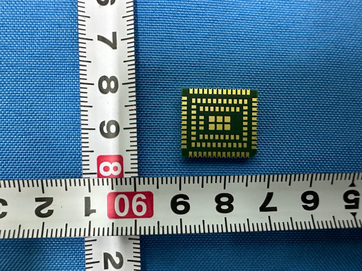
Click to zoom
Application Details
- Equipment Class
- PCB - PCS Licensed Transmitter
- Date of Grant
- Sep 08, 2024
- Application Purpose
- Original Equipment
- Date of Application
- Sep 04, 2024
- Equipment Note
- LTE Module
- Frequency Range
- 1720.00000000 - 1770.00000000
- Company
- Fibocom Wireless Inc.
- Country
- China
Documents & Files
Document Text
Text extracted from the exhibit documents filed with the FCC. Open a document above to read the original.
Users Manual
€ FIBOCOM LE270-LA Hardware Specification Copyright Copyright ©2024 Fibocom Wireless Inc. All rights reserved. Without the prior written permission of the copyright holder, any company or individual is prohibited to excerpt, copy any part of or the entire document, or transmit the document in any form. Notice The document is subject to update from time to time owing to the product version upgrade or other reasons. Unless otherwise specified, the document only serves as the user guide. All the statements, information and suggestions contained in the document do not constitute any explicit or implicit guarantee. Trademark The trademark is registered and owned by Fibocom Wireless Inc. Contact Website: https://www.fibocom.com/en/ Address: Floor 10, Building A, Shenzhen International Innovation Valley, First Stone Road, Xili Community, Xili Street, Nanshan District, Shenzhen Tel: +86 755-26733555 0 Foreword Foreword 1.1 Introduction The LE270-LA LTE Module adopt ARM CORTEX-M3 core baseband processor, with a main frequency of up to 306MHz and support for LTE network. It is a highly integrated wireless communication module. The document describes the LE270-LA electrical characteristics and basic function. 1.2 Specification 1.2.1 RF Characteristic LE270-LA RF characteristic is shown in Table 2. Table 1. RF characteristic Operating Band LTE FDD B2/B3/B4/B5/B7/B8/B28/B66 LTE TDD B38/B40/B41 WIFI SCAN Not support Bluetooth Not support GNSS Not support 1.2.2 Key Feature Table 2. Key features Specification Copyright © Fibocom Wireless Inc. 3 Data transmission LTE FDD:10.3Mbps DL/5.1Mbps UL (Cat 1) LTE TDD:9.1Mbps DL/3.1Mbps UL (Cat 1) Power Supply DC 3.4V to 4.5V, typical 3.8V LTE modulation Uplink: QPSK/16Q AM; Downlink: QPSK/16QAM/64QAM; Temperature Normal operating temperature: –30°C to +75°C Extended operating temperature: –40°C to +85°C Storage temperature: –40°C to +90°C Physical Characteristics Dimension: 15.8 × 17.7 × 2.4 mm Antenna Connector Main × 1 Function Interface SIM card interface × 2 USB 2.0 × 1 UART × 3, I2C × 2, GPIO × 4, I2S/PCMx1 System indicator × 1 ADC×2 Firmware Update USB Copyright © Fibocom Wireless Inc. 4 2.FCC Conformance information Federal Communication Commission Interference Statement This device complies with Part 15 of the FCC Rules. Operation is subject to the following two conditions: (1) This device may not cause harmful interference, and (2) this device must accept any interference received, including interference that may cause undesired operation. This equipment has been tested and found to comply with the limits for a Class B digital device, pursuant to Part 15 of the FCC Rules. These limits are designed to provide reasonable protection against harmful interference in a residential installation. This equipment generates, uses and can radiate radio frequency energy and, if not installed and used in accordance with the instructions, may cause harmful interference to radio communications. However, there is no guarantee that interference will not occur in a particular installation. If this equipment does cause harmful interference to radio or television reception, which can be determined by turning the equipment off and on, the user is encouraged to try to correct the interference by one of the following measures: -Reorient or relocate the receiving antenna. -Increase the separation between the equipment and receiver. -Connect the equipment into an outlet on a circuit different from that to which the receiver is connected. -Consult the dealer or an experienced radio/TV technician for help. Any changes or modifications not expressly approved by the party responsible for compliance could void the user's authority to operate this equipment. This transmitter must not be co-located or operating in conjunction with any other antenna or transmitter. Copyright © Fibocom Wireless Inc. 5 This device is intended only for OEM integrators under the following conditions: 1) The antenna must be installed such that 20 cm is maintained between the antenna and users, 2) The transmitter module may not be co-located with any other transmitter or antenna. As long as 2 conditions above are met, further transmitter test will not be required. However, the OEM integrator is still responsible for testing their end-product for any additional compliance requirements required with this module installed. Radiation Exposure Statement This equipment complies with FCC radiation exposure limits set forth for an uncontrolled environment. This equipment should be installed and operated with minimum distance 20 cm between the radiator & your body. Important Notice to OEM integrators 1. This module is limited to OEM installation ONLY. 2. This module is limited to installation in mobile applications, according to Part 2.1091(b). 3.The separate approval is required for all other operating configurations, including portable configurations with respect to Part 2.1093 and different antenna configurations 4.For FCC Part 15.31 (h) and (k): The host manufacturer is responsible for additional testing to verify compliance as a composite system. When testing the host device for compliance with Part 15 Subpart B, the host manufacturer is required to show compliance with Part 15 Subpart B while the transmitter module(s) are installed and operating. The modules should be Copyright © Fibocom Wireless Inc. 6 transmitting and the evaluation should confirm that the module's intentional emissions are compliant (i.e. fundamental and out of band emissions). The host manufacturer must verify that there are no additional unintentional emissions other than what is permitted in Part 15 Subpart B or emissions are complaint with the transmitter(s) rule(s). The Grantee will provide guidance to the host manufacturer for Part 15 B requirements if needed. Important Note notice that any deviation(s) from the defined parameters of the antenna trace, as described by the instructions, require that the host product manufacturer must not…
Text truncated - open the document above for the full version.
Attestation Statements
Fibocom Wireless Inc. 1101, Tow er A, Building 6, Shenzhen International, Innovation Valle y, Dashi 1st Rd, Nanshan, ShenZhen, China Tel: +8675526733555 ; Fax: +86-755-26520841 Federal Communications Commission 7435 Oaklan d Mills Road Columbia MD 21046 Subject: Certification designating a U.S. agent for service of process pursuant to Part 2.911(d)(7) To whom it may concern, [Fibocom Wireless Inc. Grantee Code ZMO, FRN:0020891057] (“the applicant”) certifies that, as of the date of the filing of application, [Fibocom Wireless USA] (“the agent”) is designated as the U.S. agent for the purpose of accepting service of process on behalf of the applicant. The information of agent are: U.S. Agent: Fibocom Wireless USA FCC Registration Number (FRN): 0033437914 Physical U.S. address: 5909 Peachtree Dunwoody Rd Ste 910 Atlant a, GA 30328 United States Contact: Lei Yao Phone: +01 (469)463-6983 Email: [email protected] The applicant accepts to maintain an agent for service of process in the United States for no less than one year after either the grantee has permanently terminated all marketing and importation of the applicable equipment within the U.S., or the conclusion of any Commission-related administrative or judicial proceeding involving the equipment, whichever is later. The agent accepts the designation by (the applicant) as the U.S. agent to accept service of process includes, but is not limited to, delivery of any correspondence, notices, orders, decisions, and requirements of administrative, legal, or judicial process related to Commission proceedings. Signed by the Applicant Signed by the Agent Name: Patrick Ma Email: [email protected] Date: April 21, 2023 Name: Lei Yao Email: [email protected] Date: April 21, 2023
Attestation Statements
Rev 1/26/2023 Fibocom Wireless Inc. Federal Communications Commission Authorization and Evaluation Division 7435 Oakland Mills Road Columbia, MD 21046 USA Date:08-31-2024 Ref: Attestation Statements Part 2.911(d)(5)(i) Filing FCC ID: ZMOLE270LA Fibocom Wireless Inc. (“the applicant”) certifies that the equipment for which authorization is sought is not “covered” equipment prohibited from receiving an equipment authorization pursuant to section 2.903 of the FCC rules. Sincerely, (Applicant signature) Patrick Ma Rev 1/26/2023 Fibocom Wireless Inc. Federal Communications Commission Authorization and Evaluation Division 7435 Oakland Mills Road Columbia, MD 21046 USA Date: 08-31-2024 Ref: Attestation Statements Part 2.911(d)(5)(ii) Filing FCC ID: ZMOLE270LA Fibocom Wireless Inc. (“the applicant”) certifies that, as of the date of the filing of the application, the applicant is not identified on the Covered List (as a specifically named entity or any of its subsidiaries or affiliates) as an entity producing “covered” equipment. Sincerely, (Applicant signature) Patrick Ma
Cover Letter(s)
Fibocom Wireless Inc. Declaration of Authorization We Name: Fibocom Wireless Inc. Address: 1101,Tower A, Building 6, Shenzhen International Innovation Valley, Dashi 1st Rd, Nanshan City: ShenZhen Country: China Declare that: Name Representative of agent: Ms. Rose Liu Agent Company name: BTL Inc. Address: No.3 Jinshagang 1 st Road, Shixia, Dalang Town City: Dong Guan Country: China is authorized to apply for Certification and signing related documents of the following product(s), including 731 form(s): Product description: LTE Module Type designation: LE270-LA Trademark: Fibocom FCC ID: ZMOLE270LA on our behalf. Date: 2024-08-31 City: ShenZhen Name: Patrick Ma Function: Certification Manager Signature: .
Cover Letter(s)
Fibocom Wireless Inc. Date: 2024-08-31 Federal Communications Commission Authorization and Evaluation Division Confidentiality Request regarding application for certification of FCC ID: ZMOLE270LA Pursuant to Sections 0.457 and 0.459 of the Commission’s Rules, we hereby request confidential treatment of information accompanying this application as outlined below: Block Diagram Schematics Operational Description 4. Schematics 5. Block Diagram 6. Operational Description Tune-up Procedure 17. Tune-up Procedure Bill(s) of Material 18. BOM The above materials contain trade secrets and proprietary information not customarily released to the public. The public disclosure of these materials may be harmful to the applicant and provide unjustified benefits to its competitors. The applicant understands that pursuant to Section 0.457 of the Rules, disclosure of this application and all accompanying documentation will not be made before the date of the Grant for this application. It is our understanding that all measurement test reports, FCC ID label format and correspondence during the certification review process cannot be granted as confidential documents and this information will be available for public review once the grant of equipment authorization is issued. Signature Patrick Ma
Cover Letter(s)
Modular Approval Request FCC (KDB 996369 D01 & Part 15.212) FCC ID: ZMOLE270LA Items to be covered by Single modular transmitters. Answer from applicant 1. The modular transmitter must have its own RF shielding. YES, Please refer to External Photos. 2. The modular transmitter must have buffered modulation/data inputs (if such inputs are provided) to ensure that the module will comply with Part 15 requirements under conditions of excessive data rates or over-modulation. YES, EC718E is used for the function. 3. The modular transmitter must have its own power supply regulation. YES, the modular has its own power supply regulation. 4. The modular transmitter must comply with the antenna requirements of Section 15.203 and 15.204(b)(c). The antenna must either be permanently attached or employ a “unique” antenna coupler (at all connections between the module and the antenna, including the cable). YES, it is Printed antenna. 5. The modular transmitter must be tested in a stand-alone configuration, i.e., the module must not be inside another device during testing. This is intended to demonstrate that the module is capable of complying with Part 15 emission limits regardless of the device into which it is eventually installed. Yes, the module is tested in a stand-alone configuration as the test photos show. 6. The modular transmitter must be equipped with either a permanently affixed label or must be capable of electronically displaying its FCC identification number in accordance with 15.212 (a)(1)(vi)(A) / (B). YES, please refer to the exhibition label sample for this module. 7. The modular transmitter must comply with any specific rule or operating requirements applicable to the transmitter and the manufacturer must provide adequate instructions along with the module to explain any such requirements. A copy of these instructions must be included in the application for equipment authorization. For example, there are very strict operational and timing requirements that must be met before a transmitter is authorized for operation under Section 15.231. For instance, data transmission is prohibited, except for operation under Section 15.231(e), in which case there are separate field strength level and timing requirements. Compliance with these requirements must be assured. YES, please refer to the user manual. 8. The modular transmitter must comply with any applicable RF exposure requirements. For example, FCC Rules in Sections 1.1310, 2.1091, 2.1093, and specific Sections of Part 15, including 15.319(i), 15.407(f), 15.253(f) and 15.255(g), require that Unlicensed PCS, UNII and millimeter wave devices perform routine environmental evaluation for RF Exposure to demonstrate compliance. In addition, spread spectrum transmitters operating under Section 15.247 are required to address RF Exposure compliance. Modular transmitters approved under other Sections of Part 15, when necessary, may also need to address certain RF Exposure concerns, typically by providing specific installation and operating instructions for users, installers and other interested parties to ensure compliance. YES, RF exposure statement is attached in the user manual. Items to be covered by Split modular transmitters. Answer from applicant 1. The modular transmitter must comply with all requirements of a single modular transmitter except for items (1) & (5) of the above single modular approval requirements. 2. Only the radio front end must be shielded. The physical crystal and tuning capacitors may be located external to the shielded radio elements. The interface between the split sections of the modular system must be digital with a minimum signalling amplitude of 150 mV peak-to-peak. 3. Control information and other data may be exchanged between the transmitter control elements and radio front end. 4. The sections of a split modular transmitter must be tested installed in a host device(s) similar to that which is representative of the platform(s) intended for use. 5. Manufacturers must ensure that only transmitter control elements and radio front end components that have been approved together are capable of operating together. The transmitter module must not operate unless it has verified that the installed transmitter control elements and radio front end have been authorized together. Manufacturers may use means including, but not limited to, coding in hardware and electronic signatures in software to meet these requirements, and must describe the methods in their application for equipment authorization. Note: A limited modular approval (LMA) may be granted for single or split modular transmitters that comply partially with the requirements above. Name and surname of applicant (or authorized representative): Patrick Ma Date: 2024-09-02 Signature: ___________________________
External Photos
Project No.: 2407C095 Page 1 of 3 ATTACHMENT PHOTOGRAPHS OF EUT Project No.: 2407C095 Page 2 of 3
ID Label/Location Info
Label: Label Location:
Internal Photos
Project No.: 2407C095 Page 3 of 3
RF Exposure Info
Report No.: BTL-FCCP-4-2407C095 Page 1 of 4 FCC RF EXPOSURE REPORT FCC ID: ZMOLE270LA Project No. : 2407C095 Equipment : LTE Module Brand Name : Fibocom Test Model : LE270-LA Series Model : N/A Applicant : Fibocom Wireless Inc. Address : 1101, Tower A, Building 6, Shenzhen International Innovation Valley, Dashi 1st Rd, Nanshan, Shenzhen, China Manufacturer : Fibocom Wireless Inc. Address : 1101, Tower A, Building 6, Shenzhen International Innovation Valley, Dashi 1st Rd, Nanshan, Shenzhen, China Factory : Fibocom Wireless Inc. Address : 1101, Tower A, Building 6, Shenzhen International Innovation Valley, Dashi 1st Rd, Nanshan, Shenzhen, China Date of Receipt : Aug. 07, 2024 Date of Test : Aug. 09, 2024 ~ Aug. 29, 2024 Issued Date : Sep. 04, 2024 Report Version : R00 Test Sample : Engineering Sample No.: SSL2024080742. Standard(s) : FCC Guidelines for Human Exposure IEEE C95.1 & FCC Part 2.1091 FCC Title 47 Part 2.1091 & KDB 447498 D01 v06 The above equipment has been tested and found compliance with the requirement of the relative standards by BTL Inc. Prepared by : Abel Cao Approved by : Steven Lu Room 108, Building 2, No.1, Yile Road, Songshan Lake Zone, Dongguan City, Guangdong, People’s Republic of China Tel: +86-769-8318-3000 Web: www.newbtl.com Service mail: [email protected] Report No.: BTL-FCCP-4-2407C095 Page 2 of 4 REPORT ISSUED HISTORY Report No. Version Description Issued Date Note BTL-FCCP-4-2407C095 R00 Original Report. Sep. 04, 2024 Valid Report No.: BTL-FCCP-4-2407C095 Page 3 of 4 1. MPE CALCULATION METHOD Calculation Method of RF Safety Distance: where: S = power density P = power input to the antenna G = power gain of the antenna in the direction of interest relative to an isotropic radiator R = distance to the center of radiation of the antenna 2. ANTENNA SPECIFICATION Brand Model Name Antenna Type Connector Gain (dBi) Note GHT-019A Dipole SMA Male J 2.85 LTE Band 2 2.98 LTE Band 4 1.32 LTE Band 5 2.21 LTE Band 7 1.71 LTE Band 38 2.21 LTE Band 41 2.98 LTE Band 66 Note: The antenna gain is provided by the manufacturer. Report No.: BTL-FCCP-4-2407C095 Page 4 of 4 3. CALCULATED RESULT Band Frequency (MHz) Max. Tune up Power (dBm) Antenna Gain (dBi) Antenna Gain (linear) Output Power to Antenna Power Density (mW/cm 2 ) Power Density Limit (mW/cm 2 ) Test Result Band 2 1850.7 25 2.85 1.93 609.54 0.1213 1.0000 Complies Band 4 1710.7 25 2.98 1.99 628.06 0.1249 1.0000 Complies Band 5 824.7 25 1.32 1.36 428.55 0.0853 0.5498 Complies Band 7 2502.5 25 2.21 1.66 526.02 0.1046 1.0000 Complies Band 38 2572.5 25 1.71 1.48 468.81 0.0933 1.0000 Complies Band 41 2572.5 25 2.21 1.66 526.02 0.1046 1.0000 Complies Band 66 2572.5 25 2.98 1.99 628.06 0.1249 1.0000 Complies Note: (1) The calculated distance is 20 cm. (2) Ratio=Power Density (S) (mW/cm 2 )/Limit of Power Density (S) (mW/cm 2 ) End of Test Report
Test Report
Report No.: BTL-FCCP-1-2407C095 Page 1 of 58 FCC Radio Test Report FCC ID: ZMOLE270LA This report concerns: Original Grant Project No. : 2407C095 Equipment : LTE Module Brand Name : Fibocom Test Model : LE270-LA Series Model : N/A Applicant : Fibocom Wireless Inc. Address : 1101, Tower A, Building 6, Shenzhen International Innovation Valley, Dashi 1st Rd, Nanshan, Shenzhen, China Manufacturer : Fibocom Wireless Inc. Address : 1101, Tower A, Building 6, Shenzhen International Innovation Valley, Dashi 1st Rd, Nanshan, Shenzhen, China Factory : Fibocom Wireless Inc. Address : 1101, Tower A, Building 6, Shenzhen International Innovation Valley, Dashi 1st Rd, Nanshan, Shenzhen, China Date of Receipt : Aug. 07, 2024 Date of Test : Aug. 09, 2024 ~ Aug. 29, 2024 Issued Date : Sep. 04, 2024 Report Version : R00 Test Sample : Engineering Sample No.: SSL2024080742. Standard(s) : 47 CFR FCC Part 22 Subpart H 47 CFR FCC Part 2 The above equipment has been tested and found compliance with the requirement of the relative standards by BTL Inc. Prepared by : Abel Cao Approved by : Steven Lu Room 108, Building 2, No.1, Yile Road, Songshan Lake Zone, Dongguan City, Guangdong, People’s Republic of China Tel: +86-769-8318-3000 Web: www.newbtl.com Service mail: [email protected] Report No.: BTL-FCCP-1-2407C095 Page 2 of 58 Declaration BTL represents to the client that testing is done in accordance with standard procedures as applicable and that test instruments used has been calibrated with standards traceable to international standard(s) and/or national standard(s). BTL's reports apply only to the specific samples tested under conditions. It is manufacture’s responsibility to ensure that additional production units of this model are manufactured with the identical electrical and mechanical components. BTL assumes no responsibility for the data provided by the customer, any statements, inferences or generalizations drawn by the customer or others from the reports issued by BTL. The report must not be used by the client to claim product certification, approval, or endorsement by A2LA or any agency of the U.S. Government. This report is the confidential property of the client. As a mutual protection to the clients, the public and ourselves, the test report shall not be reproduced, except in full, without our written approval. BTL’s laboratory quality assurance procedures are in compliance with the ISO/IEC 17025: 2017 requirements, and accredited by the conformity assessment authorities listed in this test report. BTL is not responsible for the sampling stage, so the results only apply to the sample as received. The information, data and test plan are provided by manufacturer which may affect the validity of results, so it is manufacturer’s responsibility to ensure that the apparatus meets the essential requirements of applied standards and in all the possible configurations as representative of its intended use. Limitation For the use of the authority's logo is limited unless the Test Standard(s)/Scope(s)/Item(s) mentioned in this test report is (are) included in the conformity assessment authorities acceptance respective. Please note that the measurement uncertainty is provided for informational purpose only and are not use in determining the Pass/Fail results. Report No.: BTL-FCCP-1-2407C095 Page 3 of 58 Table of Contents Page REPORT ISSUED HISTORY 5 1 . APPLICABLE STANDARDS 6 2 . SUMMARY OF TEST RESULTS 6 2.1 TEST FACILITY 7 2.2 MEASUREMENT UNCERTAINTY 7 2.3 TEST ENVIRONMENT CONDITIONS 8 3 . GENERAL INFORMATION 9 3.1 GENERAL DESCRIPTION OF EUT 9 3.2 DESCRIPTION OF TEST MODES 11 3.3 BLOCK DIGRAM SHOWING THE CONFIGURATIONOFSYSTEMTESTED 12 2.4 DESCRIPTION OF SUPPORT UNITS 12 4 . TEST RESULT 13 4.1 OUTPUT POWER MEASUREMENT 13 4.1.1 LIMIT 13 4.1.2 TEST PROCEDURE 13 4.1.3 TEST SETUP LAYOUT 13 4.1.4 TEST DEVIATION 13 4.1.5 TEST RESULTS 13 4.2 OCCUPIED BANDWIDTH MEASUREMENT 14 4.2.1 TEST PROCEDURE 14 4.2.2 TEST SETUP LAYOUT 14 4.2.3 TEST DEVIATION 14 4.2.4 TEST RESULTS 14 4.3 CONDUCTED SPURIOUS EMISSIONS MEASUREMENT 15 4.3.1 LIMIT 15 4.3.2 TEST PROCEDURES 15 4.3.3 TEST SETUP LAYOUT 15 4.3.4 TEST DEVIATION 15 4.3.5 TEST RESULTS 15 4.4 RADIATED SPURIOUS EMISSIONS MEASUREMENT 16 4.4.1 LIMIT 16 4.4.2 TEST PROCEDURES 16 4.4.3 TEST SETUP LAYOUT 17 4.4.4 TEST DEVIATION 18 4.4.5 TEST RESULTS (9KHZ TO 30MHZ) 18 4.4.6 TEST RESULTS (30MHZ TO 1000MHZ) 18 4.4.7 TEST RESULTS (ABOVE 1000MHZ) 18 Report No.: BTL-FCCP-1-2407C095 Page 4 of 58 Table of Contents Page 4.5 BAND EDGE MEASUREMENT 19 4.5.1 LIMIT 19 4.5.2 TEST PROCEDURES 19 4.5.3 TEST SETUP LAYOUT 19 4.5.4 TEST DEVIATION 19 4.5.5 TEST RESULTS 19 4.6 PEAK TO AVERAGE RATIO MEASUREMENT 20 4.6.1 LIMIT 20 4.6.2 TEST PROCEDURES 20 4.6.3 TEST SETUP LAYOUT 20 4.6.4 TEST DEVIATION 20 4.6.5 TEST RESULTS 20 4.7 FREQUENCY STABILITY MEASUREMENT 21 4.7.1 LIMIT 21 4.7.2 TEST PROCEDURES 21 4.7.3 TEST SETUP LAYOUT 21 4.7.4 TEST DEVIATION 21 4.7.5 TEST RESULTS 21 4. LIST OF MEASUREMENT EQUIPMENTS 22 5. EUT TEST PHOTO 24 APPENDIX A - OUTPUT POWER 27 APPENDIX B - OCCUPIED BANDWIDTH 32 APPENDIX C - CONDUCTED SPURIOUS EMISSIONS 37 APPENDIX D - RADIATED SPURIOUS EMISSIONS (9KHZ TO 30MHZ) 39 APPENDIX E - RADIATED SPURIOUS EMISSIONS (30MHZ TO 1000MHZ) 41 APPENDIX F - RADIATED SPURIOUS EMISSIONS (ABOVE 1000MHZ) 44 APPENDIX G - BAND EDGE 47 APPENDIX H - PEAK TO AVERAGE RATIO 52 APPENDIX I - FREQUENCY STABILITY 57 Report No.: BTL-FCCP-1-2407C095 Page 5 of 58 REPORT ISSUED HISTORY Report No. Version Description Issued Date Note BTL-FCCP-1-2407C095 R00 Original Report. Sep. 04, 2024 Valid Report No.: BTL-FCCP-1-2407C095 Page 6 of 58 1. APPLICABLE STANDARDS According to the specifications of the manufacturer, the EUT must comply with the requirements of the following standards: ANSI C63.26-2015 The following reference test guidance is not within the scope of accreditation of A2LA: FCC KDB 971168 D01 Power Meas License Digital Systems v03r01 2. SUMMARY OF TEST RESULTS Test procedures according to the techni…
Text truncated - open the document above for the full version.
Test Report
Report No.: BTL-FCCP-2-2407C095 Page 1 of 68 FCC Radio Test Report FCC ID: ZMOLE270LA This report concerns: Original Grant Project No. : 2407C095 Equipment : LTE Module Brand Name : Fibocom Test Model : LE270-LA Series Model : N/A Applicant : Fibocom Wireless Inc. Address : 1101, Tower A, Building 6, Shenzhen International Innovation Valley, Dashi 1st Rd, Nanshan, Shenzhen, China Manufacturer : Fibocom Wireless Inc. Address : 1101, Tower A, Building 6, Shenzhen International Innovation Valley, Dashi 1st Rd, Nanshan, Shenzhen, China Factory : Fibocom Wireless Inc. Address : 1101, Tower A, Building 6, Shenzhen International Innovation Valley, Dashi 1st Rd, Nanshan, Shenzhen, China Date of Receipt : Aug. 07, 2024 Date of Test : Aug. 09, 2024 ~ Aug. 29, 2024 Issued Date : Sep. 04, 2024 Report Version : R00 Test Sample : Engineering Sample No.: SSL2024080742. Standard(s) : 47 CFR FCC Part 24 Subpart E 47 CFR FCC Part 2 The above equipment has been tested and found compliance with the requirement of the relative standards by BTL Inc. Prepared by : Abel Cao Approved by : Steven Lu Room 108, Building 2, No.1, Yile Road, Songshan Lake Zone, Dongguan City, Guangdong, People’s Republic of China Tel: +86-769-8318-3000 Web: www.newbtl.com Service mail: [email protected] Report No.: BTL-FCCP-2-2407C095 Page 2 of 68 Declaration BTL represents to the client that testing is done in accordance with standard procedures as applicable and that test instruments used has been calibrated with standards traceable to international standard(s) and/or national standard(s). BTL's reports apply only to the specific samples tested under conditions. It is manufacture’s responsibility to ensure that additional production units of this model are manufactured with the identical electrical and mechanical components. BTL assumes no responsibility for the data provided by the customer, any statements, inferences or generalizations drawn by the customer or others from the reports issued by BTL. The report must not be used by the client to claim product certification, approval, or endorsement by A2LA or any agency of the U.S. Government. This report is the confidential property of the client. As a mutual protection to the clients, the public and ourselves, the test report shall not be reproduced, except in full, without our written approval. BTL’s laboratory quality assurance procedures are in compliance with the ISO/IEC 17025: 2017 requirements, and accredited by the conformity assessment authorities listed in this test report. BTL is not responsible for the sampling stage, so the results only apply to the sample as received. The information, data and test plan are provided by manufacturer which may affect the validity of results, so it is manufacturer’s responsibility to ensure that the apparatus meets the essential requirements of applied standards and in all the possible configurations as representative of its intended use. Limitation For the use of the authority's logo is limited unless the Test Standard(s)/Scope(s)/Item(s) mentioned in this test report is (are) included in the conformity assessment authorities acceptance respective. Please note that the measurement uncertainty is provided for informational purpose only and are not use in determining the Pass/Fail results. Report No.: BTL-FCCP-2-2407C095 Page 3 of 68 Table of Contents Page REPORT ISSUED HISTORY 5 1 . APPLICABLE STANDARDS 6 2 . SUMMARY OF TEST RESULTS 6 2.1 TEST FACILITY 7 2.2 MEASUREMENT UNCERTAINTY 7 2.3 TEST ENVIRONMENT CONDITIONS 8 3 . GENERAL INFORMATION 9 3.1 GENERAL DESCRIPTION OF EUT 9 3.2 DESCRIPTION OF TEST MODES 11 3.3 BLOCKDIGRAMSHOWINGTHECONFIGURATIONOFSYSTEMTESTED 12 2.4 DESCRIPTION OF SUPPORT UNITS 12 4 . TEST RESULT 13 4.1 OUTPUT POWER MEASUREMENT 13 4.1.1 LIMIT 13 4.1.2 TEST PROCEDURE 13 4.1.3 TEST SETUP LAYOUT 13 4.1.4 TEST DEVIATION 13 4.1.5 TEST RESULTS 13 4.2 OCCUPIED BANDWIDTH MEASUREMENT 14 4.2.1 TEST PROCEDURE 14 4.2.2 TEST SETUP LAYOUT 14 4.2.3 TEST DEVIATION 14 4.2.4 TEST RESULTS 14 4.3 CONDUCTED SPURIOUS EMISSIONS MEASUREMENT 15 4.3.1 LIMIT 15 4.3.2 TEST PROCEDURES 15 4.3.3 TEST SETUP LAYOUT 15 4.3.4 TEST DEVIATION 15 4.3.5 TEST RESULTS 15 4.4 RADIATED SPURIOUS EMISSIONS MEASUREMENT 16 4.4.1 LIMIT 16 4.4.2 TEST PROCEDURES 16 4.4.3 TEST SETUP LAYOUT 16 4.4.4 TEST DEVIATION 18 4.4.5 TEST RESULTS (9KHZ TO 30MHZ) 18 4.4.6 TEST RESULTS (30MHZ TO 1000MHZ) 18 4.4.7 TEST RESULTS (ABOVE 1000MHZ) 18 4.5 BAND EDGE MEASUREMENT 19 Report No.: BTL-FCCP-2-2407C095 Page 4 of 68 Table of Contents Page 4.5.1 LIMIT 19 4.5.2 TEST PROCEDURES 19 4.5.3 TEST SETUP LAYOUT 19 4.5.4 TEST DEVIATION 19 4.5.5 TEST RESULTS 19 4.6 PEAK TO AVERAGE RATIO MEASUREMENT 20 4.6.1 LIMIT 20 4.6.2 TEST PROCEDURES 20 4.6.3 TEST SETUP LAYOUT 20 4.6.4 TEST DEVIATION 20 4.6.5 TEST RESULTS 20 4.7 FREQUENCY STABILITY MEASUREMENT 21 4.7.1 LIMIT 21 4.7.2 TEST PROCEDURES 21 4.7.3 TEST SETUP LAYOUT 21 4.7.4 TEST DEVIATION 21 4.7.5 TEST RESULTS 21 4. LIST OF MEASUREMENT EQUIPMENTS 22 5. EUT TEST PHOTO 25 APPENDIX A - OUTPUT POWER 29 APPENDIX B - OCCUPIED BANDWIDTH 36 APPENDIX C - CONDUCTED SPURIOUS EMISSIONS 43 APPENDIX D - RADIATED SPURIOUS EMISSIONS (9KHZ TO 30MHZ) 45 APPENDIX E - RADIATED SPURIOUS EMISSIONS (30MHZ TO 1000MHZ) 47 APPENDIX F - RADIATED SPURIOUS EMISSIONS (ABOVE 1000MHZ) 50 APPENDIX G - BAND EDGE 53 AP…
Text truncated - open the document above for the full version.
Contact Information
Applicant
Patrick Ma(Certification Director)
Test Firm
BTL Inc.Sophia Huang
[email protected]86-769-83183000
Technical Specifications
| # | Rule Parts | Frequency Range | Power Output | Emission | Tolerance |
|---|---|---|---|---|---|
| 24 | 27 | 1.72 GHz - 1.77 GHz | 492.00 mW | 5M57W7D | 2.5 ppm |
Other Applications from Fibocom Wireless Inc.
ZMOSC162NA62
Sep 01, 20265G Module
Equipment Class
NII - Unlicensed National Information Infrastructure TXZMOSC138NA46
Aug 11, 2026SC138-NA
Equipment Class
PCB - PCS Licensed TransmitterZMOST151LGL
May 08, 20265G Dongle
Equipment Class
CXX - Communications Rcvr for use w/ licensed Tx and CBsZMOLE250LA
Feb 27, 2026LTE Module
Equipment Class
PCB - PCS Licensed TransmitterZMOLE271GL
Feb 13, 2026LTE Module
Equipment Class
PCB - PCS Licensed Transmitter