ZMOMC610LA06LTE Module
Fibocom Wireless Inc.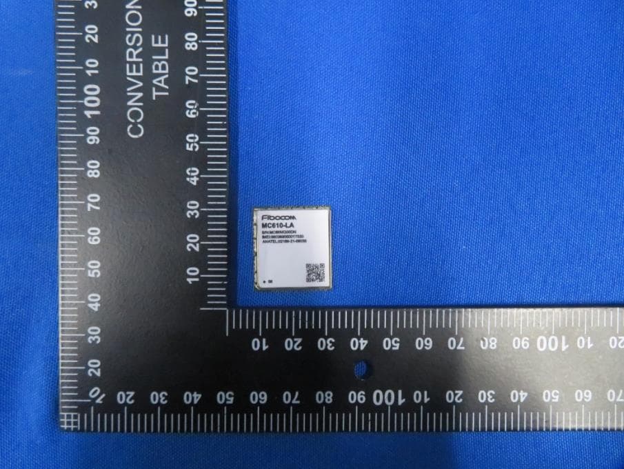
Click to zoom
Application Details
- Equipment Class
- PCB - PCS Licensed Transmitter
- Date of Grant
- Nov 21, 2022
- Application Purpose
- Original Equipment
- Date of Application
- Nov 21, 2022
- Equipment Note
- LTE Module
- Frequency Range
- 2510.00000000 - 2560.00000000
- Company
- Fibocom Wireless Inc.
- Country
- China
Documents & Files
Document Text
Text extracted from the exhibit documents filed with the FCC. Open a document above to read the original.
Users Manual
FIBOCOM MC610 Series Hardware Guide Version: V1.1.3 Date: 2022-10-27 Reproduction forbidden without Fibocom Wireless Inc. written authorization - All rights reserved. FIBOCOM MC610 Series Hardware Guide 2/71 Applicability Type No. Product Model Description 1 MC610-LA-00 Support MAIN_ANT, FDD/GSM 2 MC610-LA-02 Support MAIN_ANT, FDD/GSM, Optional support WIFI- SCAN and Bluetooth 3 MC610-EU-02 Support MAIN_ANT, FDD/GSM, Optional support WIFI- SCAN and Bluetooth 4 MC610-EU-00 Support MAIN_ANT, FDD/GSM 5 MC610-EU-03 Support MAIN_ANT, FDD/TDD/GSM 6 MC610-EU-05 Support MAIN_ANT, FDD/TDD/GSM 7 MC610-EU-07 Support MAIN_ANT, FDD/TDD/GSM, WIFI-SCAN, Bluetooth 8 MC610-LA-06 Support MAIN_ANT, FDD/GSM Reproduction forbidden without Fibocom Wireless Inc. written authorization - All rights reserved. FIBOCOM MC610 Series Hardware Guide 3/71 Copyright Copyright ©2022 Fibocom Wireless Inc. All rights reserved. Without the prior written permission of the copyright holder, any company or individual is prohibited to excerpt, copy any part of or the entire document, or transmit the document in any form. Notice The document is subject to update from time to time owing to the product version upgrade or other reasons. Unless otherwise specified, the document only serves as the user guide. All the statements, information and suggestions contained in the document do not constitute any explicit or implicit guarantee. Trademark The trademark is registered and owned by Fibocom Wireless Inc. Reproduction forbidden without Fibocom Wireless Inc. written authorization - All rights reserved. FIBOCOM MC610 Series Hardware Guide 4/71 Change History Version Author Reviewer Approver Update Description V1.1.3 Zhao Meiqing Li Chen Jin Haibo 2022-10-27 Add MC610-EU-07 and MC610- LA-06 V1.1.2 Gao Qiuqi Li Chen Jin Haibo 2022-06-30 Add MC610-EU-05 V1.1.1 Zhao Meiqing Li Chen Jin Haibo 2022-03-03 Add MC610-EU-03 V1.1.0 Xu Kaiqiang Wang Liuxia Jin Haibo 2021-10-28 Add B20 index and psm. V1.0.1 Xu Kaiqiang Wang Liuxia Jin Haibo 2021-06-23 Modify voltage range and RF index, add WIFI-SCAN /BT index. Add MC610-LA-02. Add MC610-EU-02. Add MC610-EU-00. V1.0.0 Zhao Meiqing Wang Bo Wang Yuanguang Liu Ke 2020-11-20 Initial version. Reproduction forbidden without Fibocom Wireless Inc. written authorization - All rights reserved. FIBOCOM MC610 Series Hardware Guide 5/71 Contents 1 About This Document ...................................................................................................8 1.1 Description ....................................................................................................................... 8 1.2 Safety Instructions ........................................................................................................... 8 1.3 References ...................................................................................................................... 9 1.4 Related Documents ....................................................................................................... 10 2 Product Overview ........................................................................................................ 11 2.1 Product Introduction ....................................................................................................... 11 2.2 Product Specification ..................................................................................................... 11 2.3 Hardware Diagram ......................................................................................................... 13 2.4 Operating Mode ............................................................................................................. 14 3 Application Interface ................................................................................................... 15 3.1 LCC+LGA Interface ........................................................................................................ 15 3.1.1 Pin Distribution.................................................................................................................... 15 3.1.2 Pin Definition....................................................................................................................... 16 3.1.3 Pin Multiplexing .................................................................................................................. 25 3.2 Power ............................................................................................................................ 26 3.2.1 Power Supply...................................................................................................................... 26 3.2.2 1.8 V Output ........................................................................................................................ 28 3.2.3 Power Consumption ........................................................................................................... 28 3.3 Control Signal ................................................................................................................ 30 3.3.1 Module Startup ................................................................................................................... 30 3.3.2 Module Shutdown ............................................................................................................... 32 3.3.3 Module Reset...................................................................................................................... 33 3.4 USB Interface ................................................................................................................ 35 3.4.1 USB Interface Definition ..................................................................................................... 35 3.5 USIM Interface ............................................................................................................... 36 3.5.1 USIM Pins .................................................................................................................…
Text truncated - open the document above for the full version.
Cover Letter(s)
Declaration of authorization Date: 2022.11.11 Product Name: LTE Module Model No.: MC610-LA FCC ID: ZMOMC610LA06 We, the undersigned, hereby authorize MRT Technology (Suzhou) Co., Ltd to act on our behalf, to act on our behalf in all manners relating to FCC approval of our products: report submittal, related correspondence, the signing of all documents relating to these matters, and any other lawful activity necessary to obtain such certification. Any act carried out by MRT Technology (Suzhou) Co., Ltd within the scope of this authorization shall have the same effects as our own. Name Representative of agent: Marlin Chen Agent Company name: MRT Technology (Suzhou) Co., Ltd Address: D8 Building, Youxin Industrial Park, No.2 Tian'edang Rd., Wuzhong Economic Development Zone, City: Suzhou Country: China If you have any questions regarding the authorization, please don’t hesitate to contact us. Sincerely yours, Lucy Liu Fibocom Wireless Inc. TEL: +86-755-26525092
Cover Letter(s)
Confidentiality Letter Date: 2022.11.11 Federal Communications Commission Authorization and Evaluation Division FCC ID: ZMOMC610LA06 Confidentiality Request Pursuant to FCC 47 CRF 0.457(d) and 0.459, we request that a part of the subject FCC application listed below be held permanently confidential and permanently withheld from public review due to materials that contain trade secrets and proprietary information not customarily released to the public. ⚫ Operational Description ⚫ Part List ⚫ Tune up procedure ⚫ Block Diagram ⚫ Schematics Further, the Applicant has spent substantial effort in developing this product, some aspects of which are deemed to be trade secret and proprietary. Having the subject information easily available to our competitors in this market would negate the advantage we have achieved by developing this product. Not protecting the details of the design will result in financial hardship. Sincerely yours, Lucy Liu Fibocom Wireless Inc. TEL: +86-755-26525092
Cover Letter(s)
Model Declaration Letter We, the undersigning company Company Name: Fibocom Wireless Inc. Address: 1101,Tower A, Building 6, Shenzhen International Innovation Valley, Dashi 1st Rd, Nanshan,Shenzhen,China Hereby confirm that the following products: Product description: LTE Module Type designation: MC610-LA (FCC ID: ZMOMC610LA), MC610-LA (FCC ID: ZMOMC610LA06) use identical internal printed circuit board layouts, have a common design and components. The difference only in the depopulation of components for the purposes of removing frequency bands of operation. The MC610-LA (FCC ID: ZMOMC610LA06) is the depopulated one. Date: 2022-11-15 City: Shenzhen Name: Lucy Liu Function: Certification Manager Signature:
Cover Letter(s)
Request for Modular/Limited Modular Approval Date: November 14, 2022 Subject: Manufacturer’s Declaration for ☒ - Modular Approval ☐ - Split Modular Approval ☐ - Limited Modular Approval ☐ - Limited Split Modular Approval Confidentiality Request for: ZMOMC610LA06 8 Basic Requirements – FCC Part 15.212(a)(1) For Items Marked “NO(*)”, the Limited Module Description Must be Filled Out on the Following Pages Modular Approval Requirement Requirement Met 1. The modular transmitter must have its own RF shielding. This is intended to ensure that the module does not have to rely upon the shielding provided by the device into which it is installed in order for all modular transmitter emissions to comply with FCC limits. It is also intended to prevent coupling between the RF circuitry of the module and any wires or circuits in the device into which the module is installed. Such coupling may result in non-compliant operation. The physical crystal and tuning capacitors may be located external to the shielded radio elements. 15.212(a)(1)(i) ☒ - YES ☐ - NO(*) Details: <example – The module contains a metal shield which covers all RF components and circuitry. The shield is located on the top of the board next to antenna connector> 2. The modular transmitter must have buffered modulation/data inputs (if such inputs are provided) to ensure that the module will comply with FCC requirements under conditions of excessive data rates or over-modulation. 15.212(a)(1)(ii) ☒ - YES ☐ - NO(*) Details: <example – Data to the modulation circuit is buffered as described in the operational description provided with the application> 3. The modular transmitter must have its own power supply regulation on the module. This is intended to ensure that the module will comply with FCC requirements regardless of the design of the power supplying circuitry in the device into which the module is installed. 15.212(a)(1)(iii) ☒ - YES ☐ - NO(*) Details: <example – The module contains its own power supply regulation. Please refer to schematic filed with this application> 4. The modular transmitter must comply with the antenna and transmission system requirements of §§ 15.203, 15.204(b), 15.204(c), 15.212(a), and 2.929(b). The antenna must either be permanently attached or employ a ‘‘unique’’ antenna coupler (at all connections between the module and the antenna, including the cable). The ‘‘professional installation’’ provision of § 15.203 is not applicable to modules but can apply to limited modular approvals under paragraph 15.212(b). 15.212(a)(1)(iv) ☒ - YES ☐ - NO(*) Details: <example – The module connects to its antenna using an UFL connector which is considered a non- standard connector. A list of antennas tested and approved with this device may be found in users manual provided with the application> 5. The modular transmitter must be tested in a stand-alone configuration, i.e., the module must not be inside another device during testing. This is intended to demonstrate that the module is capable of complying with Part 15 emission limits regardless of the device into which it is eventually installed. Unless the transmitter module will be battery powered, it must comply with the AC line conducted requirements found in Section 15.207. AC or DC power lines and data input/output lines connected to the module must not contain ferrites, unless they will be marketed with the module (see Section 15.27(a)). The length of these lines shall be length typical of actual use or, if that length is unknown, at least 10 centimeters to insure that there is no coupling between the case of the module and supporting equipment. Any accessories, peripherals, or support equipment connected to the module during testing shall be unmodified or commercially available (see Section 15.31(i)). 15.212(a)(1)(v) ☒ - YES ☐ - NO(*) Details: <example – The module was tested stand-alone as shown in test setup photographs filed with this application> 070920-02b Modular Approval Requirement Requirement Met 6. The modular transmitter must be labeled with its own FCC ID number, or use an electron display (see KDB Publication 784748). If using a permanently affixed label with its own FCC ID number, if the FCC ID is not visible when the module is installed inside another device, then the outside of the device into which the module is installed must also display a label referring to the enclosed module. This exterior label can use wording such as the following: “Contains Transmitter Module FCC ID: ZMOMC610LA” or “Contains FCC ID: ZMOMC610LA” Any similar wording that expresses the same meaning may be used. The Grantee may either provide such a label, an example of which must be included in the application for equipment authorization, or, must provide adequate instructions along with the module which explain this requirement. In the latter case, a copy of these instructions must be included in the application for equipment authorization. If the modular transmitter uses an electronic display of the FCC identification number, the information must be readily accessible and visible on the modular transmitter or on the device in which it is installed. If the module is installed inside another device, then the outside of the device into which the module is installed must display a label referring to the enclosed module. This exterior label can use wording such as the following: “Contains FCC certified transmitter module(s).” Any similar wording that expresses the same meaning may be used. The user manual must include instructions on how to access the electronic display. A copy of these instructions must be included in the application for equipment authorization. 15.212(a)(1)(vi) ☒ - YES ☐ - NO(*) Details: <example – There is a label on the module as shown in the labeling exhibit filed with this application. Host specific labeling instructions are shown in the installation manual .filed with this application.> 7. The modular transmitter must comply with all specific rule or operati…
Text truncated - open the document above for the full version.
Cover Letter(s)
Test Data Reuse Letter This application is intended to reuse previous test data (from FCC ID: ZMOMC610LA, certified on 08/03/2021 of initial application), since the two models of products are hardware-wise identical and only the following changes have been made: MC610-LA (FCC ID: ZMOMC610LA), MC610-LA (FCC ID: ZMOMC610LA06), use identical internal printed circuit board layouts, have a common design and components. the difference only in the depopulation of components for the purposes of removing frequency bands of operation. So, we have performed spot checks on the following items to verify that if any unexpected RF conducted power or emission changes can be noted. The test results show that all spot check data are within the instrument measurement uncertainty and data reuse is justifiable. Verification test items with 1 sample: ⚫ Conducted Power ⚫ Radiated Emission Test for the test result please refers to included exhibit “Test Reports.pdf” for detail Reuse data test items ⚫ Conducted Power / EIRP/ ERP / PAPR / OBW / Modulation characteristics / Frequency stability ⚫ Radiated Emission / Conducted Emission / Band edge Also, both the referenced application and this new application are all subject to the same FCC rule and there is no new rule update for related rules. Accordingly, we believe that the reuse data from previous certified filing is justifiable. Thank you for your attention and please feel free to contact us, if you should have any questions. Sincerely yours, Lucy Liu Fibocom Wireless Inc. TEL: +86-755-26525092
External Photos
Report No.: 2210RSU057-UE 1 of 1 EUT Photograph (1) EUT Photo (2) EUT Photo
ID Label/Location Info
Label Label Location On the top of the EUT
Internal Photos
Report No.: 2210RSU057-UE 1 of 1 EUT Photograph (1) EUT Photo
RF Exposure Info
MRT Technology (Suzhou) Co., Ltd Report No.: 2210RSU057-U2 Phone: +86-512-66308358 Report Version: V01 Web: www.mrt-cert.com Issue Date: 2022-11-15 Template Version:0.0 1 of 10 RF Exposure Evaluation Declaration FCC ID: ZMOMC610LA06 Applicant: Fibocom Wireless Inc. Product: LTE Module Model No.: MC610-LA Brand Name: Fibocom FCC Rule Part(s): FCC Part 2.1091 Result: Complies Reviewed By: Approved By: The test results relate only to the samples tested. The test results shown in the test report are traceable to the national/international standards through the calibration of the equipment and evaluated measurement uncertainty herein. The test report shall not be reproduced except in full without the written approval of MRT Technology (Suzhou) Co., Ltd. Report No.: 2210RSU057-U2 2 of 10 Revision History Report No. Version Description Issue Date Note 2210RSU057-U2 Rev. 01 Initial Report 2022-11-15 Valid Report No.: 2210RSU057-U2 3 of 10 CONTENTS Description Page 1. General Information ................................................................................................................................. 4 1.1. Applicant ........................................................................................................................................ 4 1.2. Manufacturer .................................................................................................................................. 4 1.3. Testing Facility ............................................................................................................................... 4 1.4. Product Information........................................................................................................................ 5 1.5. Antenna Details .............................................................................................................................. 5 1.6. Applied Standards.......................................................................................................................... 5 2. RF Exposure Evaluation ......................................................................................................................... 6 2.1. Test Limits ...................................................................................................................................... 6 2.2. MPE Exemptions ........................................................................................................................... 7 2.3. Device Classification ...................................................................................................................... 9 2.4. Calculated Result ......................................................................................................................... 10 Report No.: 2210RSU057-U2 4 of 10 1. General Information 1.1. Applicant Fibocom Wireless Inc. 1101, Tower A, Building 6, Shenzhen International Innovation Valley, Dashi 1st Rd, Nanshan, Shenzhen, China 1.2. Manufacturer Fibocom Wireless Inc. 1101, Tower A, Building 6, Shenzhen International Innovation Valley, Dashi 1st Rd, Nanshan, Shenzhen, China 1.3. Testing Facility Test Site – MRT Suzhou Laboratory Laboratory Location (Suzhou - Wuzhong) D8 Building, No.2 Tian’edang Rd., Wuzhong Economic Development Zone, Suzhou, China Laboratory Location (Suzhou - SIP) 4b Building, Liando U Valley, No.200 Xingpu Rd., Shengpu Town, Suzhou Industrial Park, China Laboratory Accreditations A2LA: 3628.01 CNAS: L10551 FCC: CN1166 ISED: CN0001 VCCI: R-20025 G-20034 C-20020 T-20020 R-20141 G-20134 C-20103 T-20104 Test Site – MRT Shenzhen Laboratory Laboratory Location (Shenzhen) 1G, Building A, Junxiangda Building, Zhongshanyuan Road West, Nanshan District, Shenzhen, China Laboratory Accreditations A2LA: 3628.02 CNAS: L10551 FCC: CN1284 ISED: CN0105 Test Site – MRT Taiwan Laboratory Laboratory Location (Taiwan) No. 38, Fuxing 2nd Rd., Guishan Dist., Taoyuan City 333, Taiwan (R.O.C.) Laboratory Accreditations TAF: L3261-190725 FCC: 291082, TW3261 ISED: TW3261 Report No.: 2210RSU057-U2 5 of 10 1.4. Product Information Product Name LTE Module Model No. MC610-LA Brand Name Fibocom IMEI 860369050013745 Operating Temp. -30 ~ 75°C 3GPP Specification GSM 850/1900 LTE Cat 1bis Band 5/7 Power Type 3.40 ~ 4.20Vdc, typical 3.80Vdc Remark: The information of EUT was provided by the manufacturer, and the accuracy of the information shall be the responsibility of the manufacturer. 1.5. Antenna Details Technology Frequency Range (MHz) Antenna Type MaxPeak Gain (dBi) GSM850 824 ~ 849 Fixed External Antenna 1.5 PCS1900 1710 ~ 1755 1.4 LTE Cat 1bis Band 5 824 ~ 849 1.2 LTE Cat 1bis Band 7 2500 ~ 2570 2.3 Note 1: All antenna information (Antenna type and Peak Gain) is provided by the manufacturer. Note 2: The typical antennas used to calculate the ERP (EIRP). 1.6. Applied Standards According to the specifications of the manufacturer, the EUT must comply with the requirements of the following standards: ⚫ FCC Part 2.1091 & KDB 447498 D04 Interim General RF Exposure Guidance v01 Report No.: 2210RSU057-U2 6 of 10 2. RF Exposure Evaluation 2.1. Test Limits According to FCC §1.1310: The criteria listed in the following table shall be used to evaluate the environment impact of human exposure to radio frequency (RF) radiation as specified in §1.1307(b) Limits For Maximum Permissible Exposure (MPE) Frequency Range (MHz) Electric Field Strength (V/m) Magnetic Field Strength (A/m) Power Density (mW/cm 2 ) Average Time (Minutes) (A) Limits for Occupational/ Control Exposures 0.3-3.0 614 1.63 *(100) ≤6 3.0-30 1842/f 4.89/f *(900/f 2 ) <6 30-300 61.4 0.163 1.0 <6 300-1,500 -- -- f/300 <6 1,500-100,000 -- -- 5 <6 (B) Limits for General Population/ Uncontrolled Exposures 0.3-1.34 614 1.63 *(100) <30 1.34-30 824/f 2.19/f *(180/f 2 ) <30 30-300 27.5 0.073 0.2 <30 300-1,500 -- -- f/1500 <30 1,500-100,000 -- -- 1.0 <30 f= frequency in MHz. * = Plane-wave equivalent power density. Report No.: 2210RSU057-U2 7 of 10 2.2. MPE Exemp…
Text truncated - open the document above for the full version.
Test Report
MRT Technology (Suzhou) Co., Ltd Report No.: 2210RSU057-U1 Phone: +86-512-66308358 Report Version: V01 Web: www.mrt-cert.com Issue Date: 2022-11-15 Template Version:0.0 1 of 30 RF MEASUREMENT REPORT FCC ID: ZMOMC610LA06 Application: Fibocom Wireless Inc. Product: LTE Module Model No.: MC610-LA Brand Name: Fibocom FCC Rule Part(s): Part 2, 22 (H), 24 (E), 27 Result: Complies Test Date: 2022-11-07 ~ 2022-11-10 Reviewed By: Approved By: The test results relate only to the samples tested. This equipment has been shown to be capable of compliance with the applicable technical standards as indicated in the measurement report and was tested in accordance with the measurement procedures specified in ANSI C63.26-2015. Test results reported herein relate only to the item(s) tested. The test report shall not be reproduced except in full without the written approval of MRT Technology (Suzhou) Co., Ltd. Report No.: 2210RSU057-U1 2 of 30 Revision History Report No. Version Description Issue Date Note 2210RSU057-U1 Rev. 01 Initial Report 2022-11-15 Valid Note: This application for certification is leveraging the data reuse procedures from KDB 484596 based on reference FCC ID: ZMOMC610LA to cover variant FCC ID: ZMOMC610LA06. Report No.: 2210RSU057-U1 3 of 30 CONTENTS Description Page 1. General Information .................................................................................................................................. 5 1.1. Applicant ....................................................................................................................................... 5 1.2. Manufacturer ................................................................................................................................. 5 1.3. Testing Facility .............................................................................................................................. 5 1.4. Product Information ...................................................................................................................... 6 1.5. Radio Specification Under Test..................................................................................................... 7 1.6. Description of Available Antennas ................................................................................................ 8 1.7. Test Methodology .......................................................................................................................... 9 2. Test Configuration .................................................................................................................................. 10 2.1. Test System Connection Diagram .............................................................................................. 10 2.2. Test Environment Condition ........................................................................................................ 10 3. Measuring Instrument ............................................................................................................................ 11 4. Decision Rules and Measurement Uncertainty ................................................................................... 12 4.1. Decision Rules ............................................................................................................................ 12 4.2. Measurement Uncertainty........................................................................................................... 12 5. Test Result ............................................................................................................................................... 13 5.1. Summary ..................................................................................................................................... 13 5.2. Equivalent Isotropically Radiated Power Measurement ............................................................. 14 5.2.1. Test Limit ..................................................................................................................................... 14 5.2.2. Test Procedure ............................................................................................................................ 14 5.2.3. Test Setting ................................................................................................................................. 15 5.2.4. Test Setup ................................................................................................................................... 15 5.2.5. Test Result .................................................................................................................................. 15 5.3. Radiated Spurious Emissions Measurement ............................................................................. 16 5.3.1. Test Limit ..................................................................................................................................... 16 5.3.2. Test Procedure ............................................................................................................................ 16 5.3.3. Test Setting ................................................................................................................................. 16 5.3.4. Test Setup ................................................................................................................................... 17 5.3.5. Test Result .................................................................................................................................. 18 Appendix A - Test Result ................................................................................................................................. 19 A.1 Equivalent Isotropically Radited Power Test Result ................................................................... 19 A.2 Radiated Spurious Emissions Test Result .................................................................................. 25 Appendix B - Test Setup Ph…
Text truncated - open the document above for the full version.
Test Setup Photos
Report No.: 2210RSU057-UT 1 of 1 RF Test Setup Photograph Description: Transmitter Spurious Emissions Test Setup for below 1GHz Description: Transmitter Spurious Emissions Test Setup for above 1GHz
Contact Information
Applicant
Patrick Ma(Certification Director)
Test Firm
MRT Technology (Suzhou) Co., Ltd.Mr. Marlin Chen
[email protected]8651266308358
Technical Specifications
| # | Rule Parts | Frequency Range | Power Output | Emission | Tolerance |
|---|---|---|---|---|---|
| 7 | 27 | 2.51 GHz - 2.56 GHz | 163.30 mW | 5M43W7D | 0.0077 ppm |
Other Applications from Fibocom Wireless Inc.
ZMOSC162NA62
Sep 01, 20265G Module
Equipment Class
NII - Unlicensed National Information Infrastructure TXZMOSC138NA46
Aug 11, 2026SC138-NA
Equipment Class
PCB - PCS Licensed TransmitterZMOST151LGL
May 08, 20265G Dongle
Equipment Class
CXX - Communications Rcvr for use w/ licensed Tx and CBsZMOLE250LA
Feb 27, 2026LTE Module
Equipment Class
PCB - PCS Licensed TransmitterZMOLE271GL
Feb 13, 2026LTE Module
Equipment Class
PCB - PCS Licensed Transmitter