ZOC-LDHVM200AVibration monitor with WIFI
PCB Piezotronics, Inc.
Click to zoom
Application Details
- Equipment Class
- DTS - Digital Transmission System
- Date of Grant
- Nov 30, 2015
- Application Purpose
- Original Equipment
- Date of Application
- Nov 30, 2015
- Equipment Note
- Vibration monitor with WIFI
- Frequency Range
- 2412.00000000 - 2462.00000000
- Company
- PCB Piezotronics, Inc.
- Country
- United States
Documents & Files
Document Text
Text extracted from the exhibit documents filed with the FCC. Open a document above to read the original.
Users Manual
IHVM200.01 Manual DRAFT Larson Davis HVM200 Manual DRAFT Copyright Copyright 2015 PCB Piezotronics, Inc. This manual is copyrighted, with all rights reserved. The manual may not be copied in whole or in part for any use without prior written consent of PCB Piezotronics, Inc. Trademarks PCB ® is a registered trademark of PCB Group, Inc. Apple Store is a trademark of Apple, Inc. Google Play is a trademark of Google, Inc. All other trademarks are property of their respective owners. Disclaimer The following paragraph does not apply in any state or country where such statements are not agreeable with local law: Even though PCB Piezotronics, Inc. has reviewed its documentation, PCB Piezotronics, Inc. makes no warranty or representation, either expressed or implied, with respect to this instrument and documentation, its quality, performance, merchantability, or fitness for a particular purpose. This documentation is subject to change without notice, and should not be construed as a commitment or representation by PCB Piezotronics, Inc. This publication may contain inaccuracies or typographical errors. PCB Piezotronics, Inc. will periodically update the material for inclusion in new editions. Changes and improvements to the information described in this manual may be made at any time. Recycling PCB Piezotronics, Inc. is an environmentally friendly organization and encourages our customers to be environmentally conscious. When this product reaches its end of life, please recycle the product through a local recycling center or return the product to: PCB Piezotronics, Inc. Attn: Recycling Coordinator 1681 West 820 North Provo, Utah, USA 84601-1341 where it will be accepted for disposal. Warranty For warranty information, refer to our Terms and Conditions of Sale on our website at www.larsondavis.com/TermsConditions.aspx. HVM200 Purchase Information Record the serial number and date of purchase below. Serial Number:_______________________ Date of Purchase:____________________ HVM200 ManualIntroduction1-1 CHAPTER 1 Introduction This chapter presents an overview of the HVM200 Human Vibration Meter. Features The Larson Davis HVM200 Human Vibration Meter is a Type 1 instrument designed for use in assessing vibration as perceived by human beings. The HVM200 provides the following features for vibration measurement: •Whole body, hand-arm, and general vibration applications •Wireless mobile interface •Compact design for easy wear and convenient placement •Mobile G4 measurement application for configuring, measuring, and viewing vibration data on multiple meters •Connection and control of multiple meters through Wi-Fi access ( •Support for optional 1/1 and 1/3 Octave Band Analysis •Support for full SLM Utility G4 Software analysis Standard Accessories •USB 2.0 to Micro-USB power and communications cable •Removable 64 GB SD memory Optional Accessories •1/1 and 1/3 Octave Band Analysis firmware •SLM Utility G4 for HVM Software •Larson Davis PSA035 Power Supply 1-2Transducer Selection HVM200 Manual •Larson Davis CCS048 Arm Band for wearing the HVM200 •Larson Davis SEN041F accelerometer for Hand-Arm vibration measurements •Larson Davis SEN020 accelerometer for Hand-Arm and general vibration measurements •Larson Davis SEN027 Seat Adapter, accelerometer, and adapter for whole-body vibration measurements •Larson Davis ADP063, ADP080A, ADP081A, and ADP082A adapters for accelerometer placement Optional Larson Davis CCS047 Hard Shell Case •Larson Davis CBL210-05, CBL216, and CBL217-01 cables for connection between accelerometers and HVM200 meter. •Larson Davis 394C06 Hand-held Shaker for vibrational measurement verification •Larson Davis CCS047 Hard Shell Case for transport and protection of HVM200 and accessories Transducer Selection The HVM200 requires a transducer to convert physical vibration quantities into measurable, electrical signals. In selecting a transducer for the HVM200, consider the following ICP ® or Charge Accelerometers The HVM200 has built-in ICP ® power supplies and charge amplifiers. This allows the HVM200 to interface directly with ICP or charge transducers, and eliminates the need for external signal conditioning. •ICP accelerometers are also called “Voltage Mode” or “Low impedance” and may be known by various other vendor trade names. ICP is PCB’s registered trademark which stands for “Integrated Circuit Piezoelectric” and identifies PCB sensors which incorporate built-in, signal conditioning electronics. The built-in electronics serve to convert the high impedance charge signal that is generated by the piezoelectric sensing element to a usable low impedance voltage signal which can be readily transmitted over ordinary 2 wire or coaxial cables to any voltage readout or recording device. The low impedance signal can be transmitted over long cable distances and used in dirty field or factory environments with little signal degradation HVM200 ManualTransducer Selection1-3 The HVM200 could also be utilized through an alternative direct input. This would require, however, the use of some kind of external signal conditioning unit such as an external source of ICP power, or an external charge amplifier. •Charge mode sensors output a high impedance, electrical charge signal that is generated by the piezoelectric sensing element. This signal is extremely sensitive to corruption from environmental influences. To conduct accurate measurements, it is necessary to condition this signal to a low impedance voltage before it can be input to a readout or recording device. A charge amplifier or in-line charge converter is generally used for this purpose. Transducer Sensitivity With accelerometers, the proper sensitivity depends on the application being performed. If the application is a high vibration level application, a low sensitivity should be selected. For low vibration level applications, a high sensitivity accelerometer should be used. Transverse sensitivity may also affect measurements. It is defined a…
Text truncated - open the document above for the full version.
External Photos
External Photographs Front View External Photographs Back View External Photographs Bottom View External Photographs Top View External Photographs Right Side External Photographs Left Side
Internal Photos
Internal Photographs View of Battery with Cover Off Internal Photographs View of Component Side of PCB Internal Photographs View of Circuitry under the RF Shield Internal Photographs View of Trace Side of PCB
RF Exposure Info
© 2015 RF Exposure Lab, LLC This report shall not be reproduced except in full without the written approval of RF Exposure Lab, LLC. 802 N. Twin Oaks Valley Road, Suite 105 • San Marcos, CA 92069 • U.S.A. TEL (760) 471-2100 • FAX (760) 471-2121 http://www.rfexposurelab.com CERTIFICATE OF COMPLIANCE SAR EVALUATION PCB Piezotronics, Inc. Dates of Test: September 28, 2015 Larson Davis Division Test Report Number: SAR.20150913 1681 West 820 North Revision C Provo, UT 84601 This wireless mobile and/or portable device has been shown to be compliant for localized specific absorption rate (SAR) for uncontrolled environment/general exposure limits specified in ANSI/IEEE Std. C95.1-1992 and had been tested in accordance with the measurement procedures specified in IEEE 1528-2013 and IEC 62209-2:2010 (See test report). I attest to the accuracy of the data. All measurements were performed by myself or were made under my supervision and are correct to the best of my knowledge and belief. I assume full responsibility for the completeness of these measurements and vouch for the qualifications of all persons taking them. RF Exposure Lab, LLC certifies that no party to this application is subject to a denial of Federal benefits that includes FCC benefits pursuant to Section 5301 of the Anti-Drug Abuse Act of 1988, 21 U.S.C. 853(a). Jay M. Moulton Vice President Testing Cert. # 2387.01 FCC ID: ZOC-LDHVM200A IC Certificate: 9732A-LDHVM200A Model(s): HVM200 Test Sample: Engineering Unit Same as Production Serial Number: 0000063 Equipment Type: Wireless Human Vibration Meter Classification: Portable Transmitter Next to Body TX Frequency Range: 2412 – 2462 MHz Frequency Tolerance: ± 2.5 ppm Maximum RF Output: 2450 MHz – 17.5 dBm Conducted Signal Modulation: DSSS, OFDM Antenna Type: Internal Antenna Application Type: Certification FCC Rule Parts: Part 2, 15C KDB Test Methodology: KDB 447498 D01 v05r02, KDB248227 D01 v02 Industry Canada: RSS-102 Issue 5, Safety Code 6 Maximum SAR Value: 0.39 W/kg Reported Separation Distance: 0 mm Report Number: SAR.20150913 © 2015 RF Exposure Lab, LLC Page 2 of 86 This report shall not be reproduced except in full without the written approval of RF Exposure Lab, LLC. Table of Contents 1. Introduction ........................................................................................................................ 3 SAR Definition [5] ................................................................................................................... 4 2. SAR Measurement Setup ................................................................................................... 5 Robotic System ...................................................................................................................... 5 System Hardware ................................................................................................................... 5 System Electronics ................................................................................................................. 6 Probe Measurement System .................................................................................................. 6 3. Probe and Dipole Calibration .............................................................................................14 4. Phantom & Simulating Tissue Specifications .....................................................................15 Head & Body Simulating Mixture Characterization ................................................................15 5. ANSI/IEEE C95.1 – 1992 RF Exposure Limits [2] ..............................................................16 Uncontrolled Environment .....................................................................................................16 Controlled Environment .........................................................................................................16 6. Measurement Uncertainty .................................................................................................17 7. System Validation..............................................................................................................18 Tissue Verification .................................................................................................................18 Test System Verification ........................................................................................................18 8. SAR Test Data Summary ..................................................................................................19 Procedures Used To Establish Test Signal ...........................................................................19 Device Test Condition ...........................................................................................................19 SAR Data Summary – 2450 MHz Body .................................................................................22 9. Test Equipment List ...........................................................................................................23 10. Conclusion ....................................................................................................................24 11. References ....................................................................................................................25 Appendix A – System Validation Plots and Data .......................................................................26 Appendix B – SAR Test Data Plots ...........................................................................................31 Appendix C – SAR Test Setup Photos ......................................................................................33 Appendix D – Probe Calibration Data Sheets ............................................................................41 Appendix E – Dipole Calibration Data Sheets ...........................................................................53 Appendix F – Phantom Calibration Data Sheets .............…
Text truncated - open the document above for the full version.
Test Report
Nemko-CCL, Inc. 1940 West Alexander Street Salt Lake City, UT 84119 801-972-6146 Test Report Certification Test Of: HVM200 FCC ID: ZOC-LDHVM200A Test Specifications: FCC PART 15, Subpart C Test Report Serial No: 285165-2.3 Applicant: PCB Piezotronics, Inc. 3425 Walden Avenue Depew, NY 14043-2495 U.S.A Dates of Test: September 21 & 22, 2015 Report Issue Date: November 25, 2015 Accredited Testing Laboratory By: NVLAP Lab Code 100272-0 Nemko-CCL, Inc. TEST REPORT: 285165-2.3 REPORT ISSUE DATE: 11/25/2015 Page 2 of 70 TRF-15.247 DTS SUBC Issue 2 Sept.. 2015 CERTIFICATION OF ENGINEERING REPORT This report has been prepared by Nemko-CCL, Inc. to document compliance of the device described below with the requirements of Federal Communications Commission (FCC) Part 15, Subpart C. This report may be reproduced in full, partial reproduction may only be made with the written consent of the laboratory. The results in this report apply only to the sample tested. - Applicant: PCB Piezotronics, Inc. - Manufacturer: PCB Piezotronics, Inc. - Brand Name: Larson Davis - Model Number: HVM200 - FCC ID: ZOC-LDHVM200A On this 25 th day of November 2015, I, individually and for Nemko-CCL, Inc., certify that the statements made in this engineering report are true, complete, and correct to the best of my knowledge, and are made in good faith. Although NVLAP has recognized that the Nemko-CCL, Inc. EMC testing facilities are in good standing, this report must not be used to claim product certification, approval, or endorsement by NVLAP, NIST, or any agency of the federal government. Nemko-CCL, Inc. Tested by: Norman P. Hansen Test Technician Reviewed by: Thomas C. Jackson Certification Manager Nemko-CCL, Inc. TEST REPORT: 285165-2.3 REPORT ISSUE DATE: 11/25/2015 Page 3 of 70 TRF-15.247 DTS SUBC Issue 2 Sept.. 2015 Revision History Revision Description Date 1 Original Report Release November 10, 2015 At the request of the TCB the following changes were made: 2 Revised the testing procedures to ANSI C63.10: 2013. Updated equipment list in A1.3 Radiated Emissions. November 23, 2015 3 Revised A1.3, paragraph 6, to correctly reference the EUT placement during testing. November 25, 2015 Nemko-CCL, Inc. TEST REPORT: 285165-2.3 REPORT ISSUE DATE: 11/25/2015 Page 4 of 70 TRF-15.247 DTS SUBC Issue 2 Sept.. 2015 TABLE OF CONTENTS PAGE SECTION 1.0 CLIENT INFORMATION .................................................................................5 SECTION 2.0 EQUIPMENT UNDER TEST (EUT)..................................................................6 SECTION 3.0 TEST SPECIFICATION, METHODS & PROCEDURES .............................8 SECTION 4.0 OPERATION OF EUT DURING TESTING..................................................14 SECTION 5.0 SUMMARY OF TEST RESULTS ...................................................................15 SECTION 6.0 MEASUREMENTS AND RESULTS ...............................................................16 APPENDIX 1 TEST PROCEDURES AND TEST EQUIPMENT .........................................52 APPENDIX 2 PHOTOGRAPHS ................................................................................................57 Nemko-CCL, Inc. TEST REPORT: 285165-2.3 REPORT ISSUE DATE: 11/25/2015 Page 5 of 70 TRF-15.247 DTS SUBC Issue 2 Sept.. 2015 SECTION 1.0 CLIENT INFORMATION 1.1 Applicant: Company Name: PCB Piezotronics, Inc. 3425 Walden Avenue Depew, NY 14043-2495 U.S.A Contact Name: Dave Corelli Title: Director Application Engineering 1.2 Manufacturer: Company Name: PCB Piezotronics, Inc. 3425 Walden Avenue Depew, NY 14043-2495 U.S.A Contact Name: Dave Corelli Title: Director Application Engineering Nemko-CCL, Inc. TEST REPORT: 285165-2.3 REPORT ISSUE DATE: 11/25/2015 Page 6 of 70 TRF-15.247 DTS SUBC Issue 2 Sept.. 2015 SECTION 2.0 EQUIPMENT UNDER TEST (EUT) 2.1 Identification of EUT: Brand Name: Larson Davis Model Number: HVM200 Serial Number: 0000064 Dimensions: 11 cm x 7 cm x 1.8 cm 2.2 Description of EUT: The HVM200 is a vibration monitor and data collection system that is worn on a person’s arm. A Sen041F sensor was used in testing and connected to the HVM200 via a CBL217-01 33 cm cable. A microUSB port is provided for data transfer or charging the battery. A RAVPower RC-EB-L1G6LLU, 3.8 V, 2250 mAh battery powers the HVM200. An 802.11bg transceiver is used for communication with other devices. The transceiver uses a Johanson Technology 2450AT18A100 chip antenna with a maximum gain of 0.5 dBi. This report covers the circuitry of the devices subject to FCC Part 15, Subpart C. The circuitry of the device subject to FCC Subpart B was found to be compliant and is covered in Nemko-CCL, Inc. report 285165-7. 2.3 EUT and Support Equipment: The FCC ID numbers for all the EUT and support equipment used during the test are listed below: Brand Name Model Number Serial Number FCC ID Number or Compliance Description Name of Interface Ports / Interface Cables BN: Larson Davis MN: HVM200 (Note 1) SN: 0000064 ZOC- LDHVM200A Vibration Monitor See Section 2.4 BN: Larson Davis MN: SEN041F SN: P186462 None Sensor – triaxial accelerometer Interface/Larson Davis CBL217-01 cable assembly BN: Trendnet MN: TE100-S8P SN: 0243C3A16540 DoC Network Switch LAN/Cat 5e cables Nemko-CCL, Inc. TEST REPORT: 285165-2.3 REPORT ISSUE DATE: 11/25/2015 Page 7 of 70 TRF-15.247 DTS SUBC Issue 2 Sept.. 2015 Brand Name Model Number Serial Number FCC ID Number or Compliance Description Name of Interface Ports / Interface Cables BN: Samsung MN: N130 SN: LCM93HS900480X Declaration of Conformity Netbook Computer USB/USB cable (Note 2) Ethernet/Cat 5e cable Note: (1) EUT (2) Interface port connected to EUT (See Section 2.4) The support equipment listed above was not modified in order to achieve compliance with this standard. 2.4 Interface Ports on EUT: Name of Ports No. of Ports Fitted to EUT Cable Descriptions/Length USB/Charge 1 USB A to micro USB cable/1.2 meters Sensor Interface 1 4 conductor cable/33 cm 2.5 Modification Incorporated/Special Access…
Text truncated - open the document above for the full version.
Test Setup Photos
Setup Photographs Front View Radiated Disturbance Worst Case Configuration Setup Photographs Back View Radiated Disturbance Worst Case Configuration Setup Photographs Front View Conducted Disturbance Worst Case Configuration Setup Photographs Back View Conducted Disturbance Worst Case Configuration
Contact Information
Applicant
Lance Pellens(Quality Management System Representative)
Test Firm
Nemko-CCL incThomas Jackson
Technical Specifications
| # | Rule Parts | Frequency Range | Power Output |
|---|---|---|---|
| 1 | 15C | 2.41 GHz - 2.46 GHz | 48.50 mW |
Other Applications from PCB Piezotronics, Inc.
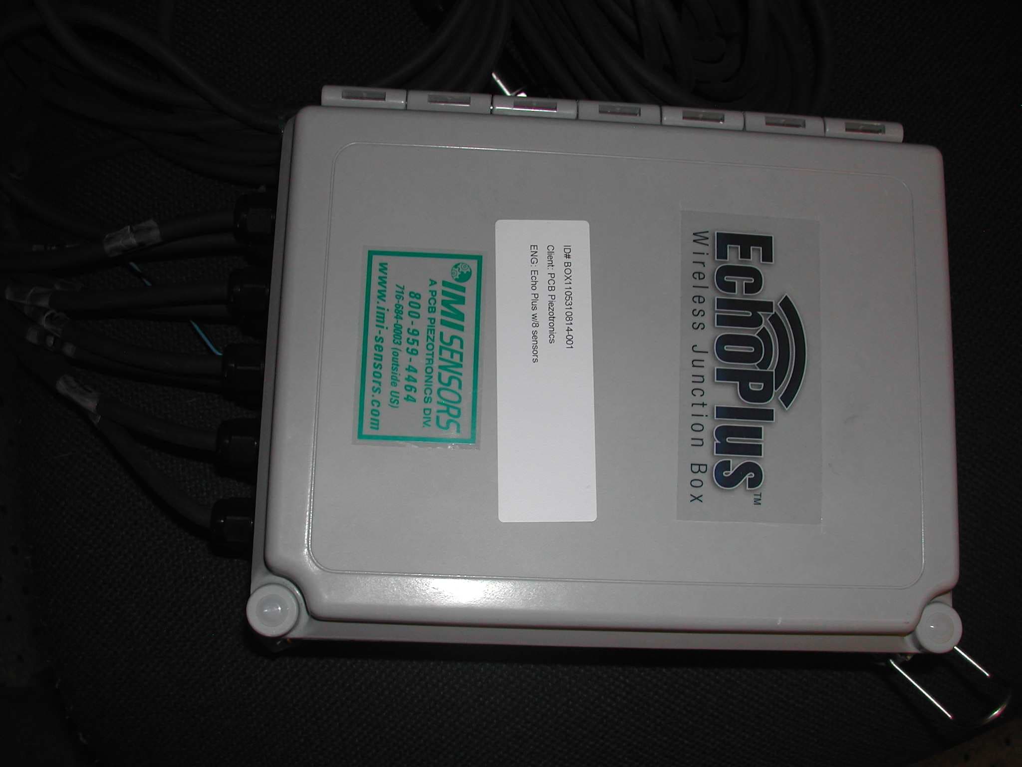
ZOC-IMI672A01
Aug 25, 2011Wireless Junction Box
Equipment Class
DXX - Part 15 Low Power Communication Device Transmitter
ZOC-IMI670A01
Aug 25, 2011Wireless Vibration Sensor
Equipment Class
DXX - Part 15 Low Power Communication Device Transmitter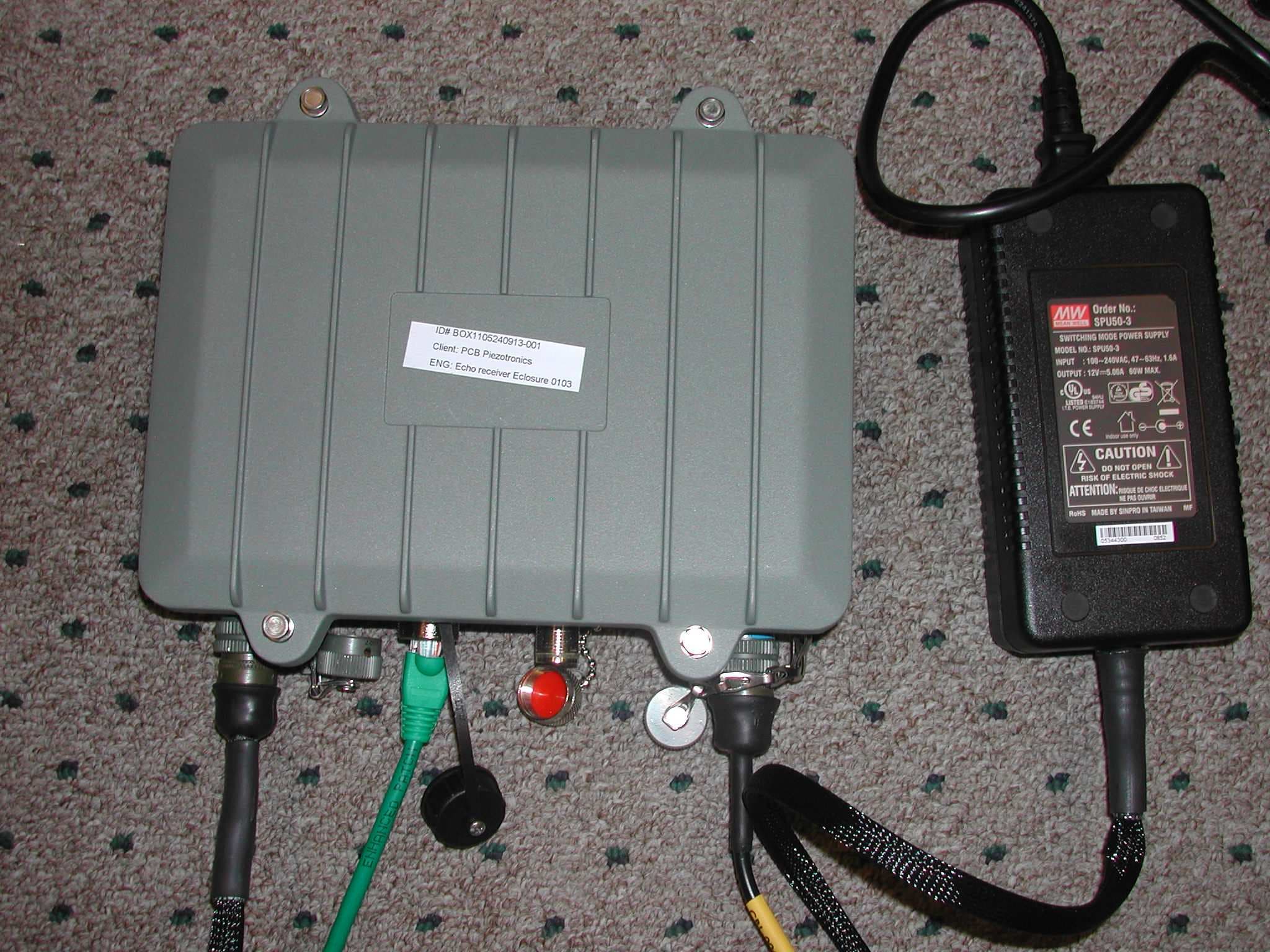
ZOC-IMI673A01
Aug 25, 2011Receiver
Equipment Class
CYY - Communications Receiver used w/Pt 15 Transmitter