Text extracted from the exhibit documents filed with the FCC. Open a document above to read the original.
Rhein Tech Laboratories, Inc. Client: C2 Development 360 Herndon Parkway Model: 3000-0003 Suite 1400 Standard: FCC 15.249 Herndon, VA 20170 http://www.rheintech.com FCC ID: ZOM-30000003 Report #: 2011091 Page 27 of 35 Appendix I: Manual Please see the following pages. C2 Development, Inc. 2.4GHz RF Module – 3000-0003 Page 1 of 6 2.4GHz RF Module PN: 3000- 0003 Date Version Revision Author July 5, 2011 1 Initial Release CC / JJ C2 Development, Inc. 2.4GHz RF Module – 3000-0003 Page 2 of 6 Technical Specifications RF Characteristics Minimum Carrier Frequency 2433 MHz Maximum Carrier Frequency 2480 MHz Rx Bandwidth 232.1 KHz Channels 30 Modulation 2- FSK Data Rate 15K Baud Raw Packet Length 11 – 18 Bytes, variable Payload 1 – 8 Bytes, variable Tx Power +1 dBm, Fixed Channel Frequency(MHz) Channel Frequency(MHz) 0 2433 15 2457.6 1 2435.2 16 2459.2 2 2436.8 17 2460.8 3 2438.4 18 2462.4 4 2440 19 2464 5 2441.6 20 2465.6 6 2443.2 21 2467.2 7 2444.8 22 2468.8 8 2446.4 23 2470.4 9 2448 24 2472 10 2449.6 25 2473.6 11 2451.2 26 2475.2 12 2452.8 27 2476.8 13 2454.4 28 2478.4 14 2456 29 2480 C2 Development, Inc. 2.4GHz RF Module – 3000-0003 Page 3 of 6 Communication Protocol RF Packet Protocol (Tx and Rx) 4 Bytes 2 Bytes 1 Byte 1 Byte 1 – 8 Bytes 2 Bytes Preamble Sync Length Node Payload CRC Preamble – 4 Bytes of alternating 1’s and 0’s. Sync – Two byte Sync word used to align data. Value is always 0xD391. Length – Packet Length in bytes, equal to the length of the Payload + 1. Node – Node Address. Composite Master/Slave ID. The Master ID is in the upper 4 bits and the Slave ID is in the lower 4 bits. For Discovery Mode, this byte is set to 00. Payload – The payload, 1 to 8 bytes. CRC – 16 bit CRC starting with the Length byte and ending with the last payload byte. UART Data Packet Protocol (Master Only) Any data sent to the adapter via the UART Rx line must adhere to the following protocol: 1 Byte 1 Byte 1 to 8 Bytes, variable Packet Length Slave ID Payload Length – Total length of the packet in bytes (Payload + 1). The upper 4 bits always contain the value 0xA0, and the lower 4 bits contain the byte length. Valid byte lengths are 0x01 through 0x08. SlaveID – Destination of packet. The upper 3 bits always contain the value 0xA0, and the lower 5 bits define the Slave ID. Valid values are 1 through 31. Payload – The payload, 1 to 8 bytes. UART Data Packet Protocol (Slave Only) Data that is sent out of the adapter via the UART Tx line is formatted as follows: 1 Byte 1 to 8 Bytes, variable Payload Length Payload Payload Length – Total length of the payload in bytes. Valid values are 1 though 8. Payload – The payload data. RF ACK Packet Protocol ( Sent by Masters, Received and Sent by Slaves) 1 Byte 1 Byte 1 Byte 1 Byte Packet Length Composite ID ACK Command Master’s ID Packet Length – Packet Length, always set to 0x03. Composite ID – The upper 4 bits contain the Master’s ID, and the lower 4 bits contain the Slave’s ID. ACK Command – Always the value 0xA9. Master’s ID - Master ID in lower 4 bits. C2 Development, Inc. 2.4GHz RF Module – 3000-0003 Page 4 of 6 RF Discovery Packet Protocol 1 Byte 1 Byte 1 Byte 1 Byte 1 Byte 1 Byte Packet Length Discovery ID Discovery Cmd New Master ID New Slave ID New Channel Packet Length – Packet length, always set to 0x05. Discovery ID – Composite Discovery ID, set to 0x00 in current versions. Discovery Cmd – Discovery Command, always set to 0xAF. New Master ID – The new ID of the Master that the Slave must use. New Slave ID – The new ID that the Slave must use as its node address. New Channel – The new channel frequency that the Slave must use for all future reception (1 - 29). End User Programming In order for two or more adapters to communicate, one adapter must be set up as a Master and all others (1 through 31) must be configured as slaves. After a reset, all modules are locked in a special mode, waiting for Master/Slave programming. This mode is indicated by either Red or Green LEDs on, but not both. Pushing and releasing the button will toggle between Red and Green. STEP 1: Factory Reset Procedure 1) While Holding down the button, apply power to the adapter. 2) Continue to hold down the button for approximately 5 seconds, or until the both LEDs illuminate. 2) Release the button. The Red LED will be on and the Green LED goes off. STEP 2: Master/Slave Setup Procedure 1) Pressing and releasing the button will toggle the LEDs. To setup an adapter as a Master, press and release the button until the Green LED is on. To setup as a slave, press and release the button until the Red LED is on. 2) While the desired LED is on (Red=Slave, Master=Green), press and hold down the button for at least 5 seconds. 3) When both LEDs turn off, release the button. Both LEDs should now be on. STEP 3: Discovery Mode Procedure Discovery Mode links a single Master to one or more Slaves. Discovery Mode mjst be run immediately after the Master/Salve Setup Procedure is complete. To run Discovery Mode: 1) Press and release the button on the Master wireless adapter. Both the Red and Green LEDs will flash. 2) Within 30 seconds, press and release the button on the LEFTMOST Slave adapter. Both the Red and Green LEDs will flash. 3) After a few seconds, the Red LED will turn off and the Green LED will turn on at both adapters. To configure multiple slaves, it is important that the slaves be set up in sequence. The LEFT MOST RF module should be the FIRST Slave selected. To program additional slaves, press the button on the Master again, followed by the button on the next Slave, going from left to right until all slaves are programmed. Slave #1 Slave #2 Slave #31 Fixture .... Module Module Module C2 Development, Inc. 2.4GHz RF Module – 3000-0003 Page 5 of 6 At this point, all adapters have been programmed and are ready for use. NOTE: After a Slave is programmed, the button no longer functions to run Discovery mode. The button changed functionality and is now be used to view the Slave’s ID number. The pr…
Text truncated - open the document above for the full version.
Rhein Tech Laboratories, Inc. Client: C2 Development 360 Herndon Parkway Model: 3000-0003 Suite 1400 Standard: FCC 15.249 Herndon, VA 20170 http://www.rheintech.com FCC ID: ZOM-30000003 Report #: 2011091 Page 20 of 35 Appendix B: FCC/TCB Agency Authorization Letter Please see the following page. June 20, 2011 American Certification Body, Inc. 6731 Whittier Avenue Suite C110 McLean, VA 22101 To Whom It May Concern: Rhein Tech Laboratories, Inc. is authorized to act on our behalf, until otherwise notified, for applications to American Certification Body, Inc. (ACB). We certify that we are not subject to denial of federal benefits, that includes FCC benefits, pursuant to Section 5301 of the Anti-Drug Abuse Act of 1988, 21 U.S.C. 862. Further, no party, as defined in 47 CFR 1.2002 (b), to the application is subject to denial of federal benefits, that includes FCC benefits. Thank you, Agency Agreement Expiration Date: 3/1/2012 Christian Clough President C2 Development, Inc. 515.233.5105 ext 101
Rhein Tech Laboratories, Inc. Client: C2 Development 360 Herndon Parkway Model: 3000-0003 Suite 1400 Standard: FCC 15.249 Herndon, VA 20170 http://www.rheintech.com FCC ID: ZOM-30000003 Report #: 2011091 Page 21 of 35 Appendix C: FCC Confidentiality Request Letter Please see the following page. June 20, 2011 American Certification Body, Inc. 6731 Whittier Avenue Suite C110 McLean, VA 22101 To Whom It May Concern: The following information is to be held confidential pursuant to FCC 47 CFR §0.457(d) and §0.459, because the information provided contains trade secrets and is proprietary. If made public, the information might be used to the disadvantage of the applicant in the market place. • Schematics • Technical Product Description • Block Diagram Sincerely, Christian Clough President
Rhein Tech Laboratories, Inc. Client: C2 Development 360 Herndon Parkway Model: 3000-0003 Suite 1400 Standard: FCC 15.249 Herndon, VA 20170 http://www.rheintech.com FCC ID: ZOM-30000003 Report #: 2011091 Page 22 of 35 Appendix D: DA00-1407 Part 15 Unlicensed Modular TX Attestation Please see the following page. July 3, 2011 To whom it may concern: The following is to satisfy the requirements of DA00-1407 Part 15 Unlicensed Modular TX. 1. The modular transmitter must have its own RF shielding Module electronics are enclosed in RF shield which is mounted at time of production. See internal photos exhibit. 2. The modular transmitter must have buffered modulation/data inputs Module contains buffered data inputs to comply with Part 15 requirements using U2. See schematic exhibit. 3. The modular transmitter must have its own power supply regulation Module contains its own power supply regulation, insuring that Part 15 compliance is maintained. See U1 on schematic exhibit. 4. The modular transmitter must comply with the antenna requirements of § 15.203 and §15.204(c) Module has permanently mounted PCB trace antenna meeting FCC antenna requirements. See internal photos and antenna specifications in operational description. 5. The modular transmitter must be tested in a stand-alone configuration Module was tested in a stand-alone configuration, and meets requirements the conducted emissions requirements of §15.207. See test report for EUT setup. 6. The modular transmitter must be labeled with its own FCC ID The module will have a silk screen label on the bottom side of the module board displaying the FCC ID. When module is used with host, a label on the exterior of the host will state “Contains FCC ID: ZOM-30000003” or equivalent. See label and location exhibit. 7. The modular transmitter must comply with any specific rule or operating requirements applicable to the transmitter and the manufacturer must provide adequate instructions along with the module to explain any such requirements. Meets requirements of § 15.247. See user manual exhibit. 8. The modular transmitter must comply with any applicable RF exposure requirements. Meets applicable RF exposure requirements as defined by § 15.247. See test report exhibit. Sincerely, Chris Clough President C2 Development, Inc.
Rhein Tech Laboratories, Inc. Client: C2 Development 360 Herndon Parkway Model: 3000-0003 Suite 1400 Standard: FCC 15.249 Herndon, VA 20170 http://www.rheintech.com FCC ID: ZOM-30000003 Report #: 2011091 Page 32 of 35 Appendix K: External Photographs Photograph 7: Top of Module with Shield Photograph 8: Top of Module without Shield Rhein Tech Laboratories, Inc. Client: C2 Development 360 Herndon Parkway Model: 3000-0003 Suite 1400 Standard: FCC 15.249 Herndon, VA 20170 http://www.rheintech.com FCC ID: ZOM-30000003 Report #: 2011091 Page 33 of 35 Photograph 9: Bottom of Module
Rhein Tech Laboratories, Inc. Client: C2 Development 360 Herndon Parkway Model: 3000-0003 Suite 1400 Standard: FCC 15.249 Herndon, VA 20170 http://www.rheintech.com FCC ID: ZOM-30000003 Report #: 2011091 Page 23 of 35 Appendix E: Label and Label Location Photograph 1: FCC ID Label Sample and Location on EUT Bottom Photograph 2: Sample “Contains FCC ID” Label for Typical Host
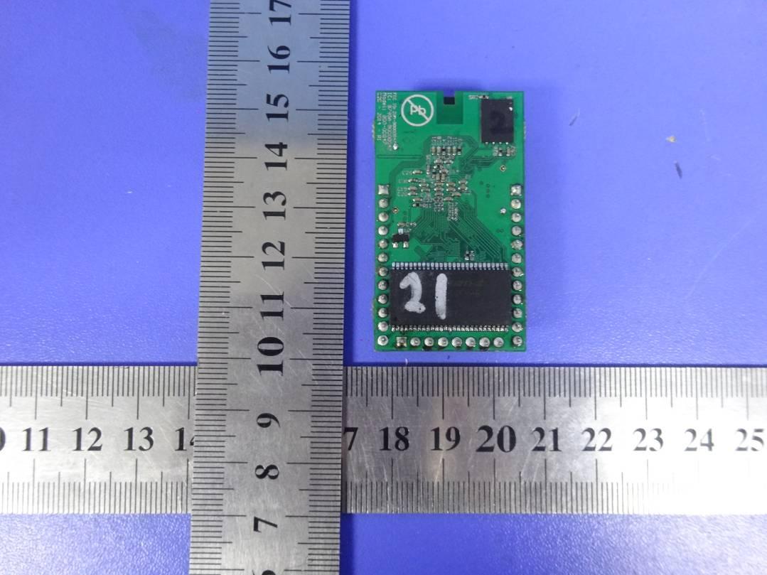
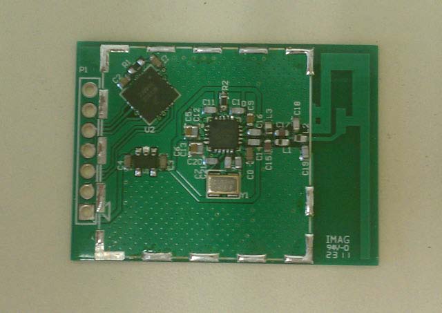
Rhein Tech Laboratories, Inc. Client: C2 Development 360 Herndon Parkway Model: 3000-0003 Suite 1400 Standard: FCC 15.249 Herndon, VA 20170 http://www.rheintech.com FCC ID: ZOM-30000003 Report #: 2011091 Page 34 of 35 Appendix L: Internal Photographs Photograph 10: Top of Module with Shield Photograph 11: Top of Module without Shield Rhein Tech Laboratories, Inc. Client: C2 Development 360 Herndon Parkway Model: 3000-0003 Suite 1400 Standard: FCC 15.249 Herndon, VA 20170 http://www.rheintech.com FCC ID: ZOM-30000003 Report #: 2011091 Page 35 of 35 Photograph 12: Bottom of Module
Engineering Solutions & Electromagnetic Compatibility Services 360 Herndon Pkwy | Suite 1400 | Herndon | Virginia 20170 Phone: 703.689.0368 | Fax: 703.689.2056 | www.rheintech.com FCC Part 15.249 Certification Application Report for Full Modular Approval Test Lab: Rhein Tech Laboratories, Inc. Phone: 703- 689- 0368 360 Herndon Parkway Fax: 703- 689- 2056 Suite 1400 Web: www.rheintech.com Herndon, VA 20170 Email: Applicant: [email protected] C2 Development, Inc. Phone: 515-233- 5105 x101 1606 Golden Aspen Drive, Suite 106 Ames, IA 50010 Contact: Christian Clough FCC ID: ZOM -30000003 Test Report Date June 28, 2011 Platform N/A RTL Work Order Number 2011091 Model # 3000-0003 RTL Quote Number QRTL10-208 American National Standard Institute ANSI C63.4-2003: Methods of Measurement of Radio-Noise Emissions from Low- Voltage Electrical and Electronic Equipment in the Range of 9 kHz to 40 GHz FCC Classification DXX – Part 15 Low Power Communication Device Transmitter FCC Rule Part(s) Part 15.249 (10-01- 10): Operation within the bands 902-928 MHz, 2400-2483.5 MHz, 5725-5850 MHz, and 24.0-24.25 GHz Frequency Range (MHz) Output Power (W) Frequency Tolerance Emission Designator 2433.585 - 2479.978 N/A N/A 1M00F2D I, the undersigned, hereby declare that the equipment tested and referenced in this report conforms to the identified standard(s) as described in this test report. No modifications were made to the equipment during testing in order to achieve compliance with these standards. Furthermore, there was no deviation from, additions to, or exclusions from, the applicable parts of FCC Part 2, FCC Part 15, and ANSI C63.4. Signature: Date: June 28, 2011 Typed/Printed Name: Desmond A. Fraser Position: President This report may not be reproduced, except in full, without the written approval of Rhein Tech Laboratories, Inc. and C2 Development, Inc. The test results relate only to the item(s) tested. These tests are accredited and meet the requirements of ISO/IEC 17025 as verified by ANSI-ASQ National Accreditation Board/ACLASS. Refer to certificate and scope of accreditation AT-1445. Rhein Tech Laboratories, Inc. Client: C2 Development 360 Herndon Parkway Model: 3000-0003 Suite 1400 Standard: FCC 15.249 Herndon, VA 20170 http://www.rheintech.com FCC ID: ZOM-30000003 Report #: 2011091 Page 2 of 35 Table of Contents 1 General Information .............................................................................................................................. 4 1.1 Scope ............................................................................................................................................ 4 1.2 Modifications ................................................................................................................................. 4 1.3 Test Facility ................................................................................................................................... 4 1.4 Related Submittal(s)/Grant(s) ....................................................................................................... 4 2 Test Information .................................................................................................................................... 5 2.1 Test Justification ........................................................................................................................... 5 2.2 Exercising the EUT ....................................................................................................................... 5 2.3 Test Result Summary .................................................................................................................... 5 2.4 Test System Details ...................................................................................................................... 5 2.5 Configuration of Tested System .................................................................................................... 6 3 Conducted AC Emissions – FCC 15.207 .............................................................................................. 7 3.1 Site and Test Description .............................................................................................................. 7 3.2 Test Limits ..................................................................................................................................... 7 3.3 Conducted AC Emissions Test Data ............................................................................................. 8 4 Duty Cycle Correction Calculation ...................................................................................................... 11 5 Radiated Emission Limits Fundamental Emissions – FCC 15.249 .................................................... 13 5.1 Radiated Emission Limits Test Procedure .................................................................................. 13 5.2 Radiated Emission Limits Test Data ........................................................................................... 13 6 Radiated Emission Limits Radiated Harmonics – FCC 15.249 .......................................................... 15 6.1 Radiated Emission Limits Test Procedure .................................................................................. 15 6.2 Radiated Emissions Test Data .................................................................................................... 15 7 Conclusion .......................................................................................................................................... 18 Rhein Tech Laboratories, Inc. Client: C2 Development 360 Herndon Parkway Model: 3000-0003 Suite 1400 Standard: FCC 15.249 Herndon, VA 20170 http://www.rheintech.com FCC ID: ZOM-30000003 Report #: 2011091 Page 3 of 35 Table Index Table 2-1: Test Result Summary with FCC Rules and Regulations ...................................................... 5 Table 2-2: Equipment under Test (EUT) ..................…
Text truncated - open the document above for the full version.
Rhein Tech Laboratories, Inc. Client: C2 Development 360 Herndon Parkway Model: 3000-0003 Suite 1400 Standard: FCC 15.249 Herndon, VA 20170 http://www.rheintech.com FCC ID: ZOM-30000003 Report #: 2011091 Page 28 of 35 Appendix J: Test Photographs Photograph 3: Radiated Emissions - Fr ont View Rhein Tech Laboratories, Inc. Client: C2 Development 360 Herndon Parkway Model: 3000-0003 Suite 1400 Standard: FCC 15.249 Herndon, VA 20170 http://www.rheintech.com FCC ID: ZOM-30000003 Report #: 2011091 Page 29 of 35 Photograph 4: Radiated Emissions - Rear View Rhein Tech Laboratories, Inc. Client: C2 Development 360 Herndon Parkway Model: 3000-0003 Suite 1400 Standard: FCC 15.249 Herndon, VA 20170 http://www.rheintech.com FCC ID: ZOM-30000003 Report #: 2011091 Page 30 of 35 Photograph 5: Conducted AC Emissions - Front View Rhein Tech Laboratories, Inc. Client: C2 Development 360 Herndon Parkway Model: 3000-0003 Suite 1400 Standard: FCC 15.249 Herndon, VA 20170 http://www.rheintech.com FCC ID: ZOM-30000003 Report #: 2011091 Page 31 of 35 Photograph 6: Conducted AC Emissions - Rear View
360 Herndon Parkway · Herndon · United States
| # | Rule Parts | Frequency Range | Power Output |
|---|---|---|---|
| 1 | 15C | 2.43 GHz - 2.48 GHz | - |

802.11b/g/n (2.4GHz only) Module
Equipment Class
DTS - Digital Transmission System