ZRV-SPGClarity Wireless Gateways
Solar Power Technologies Incorporated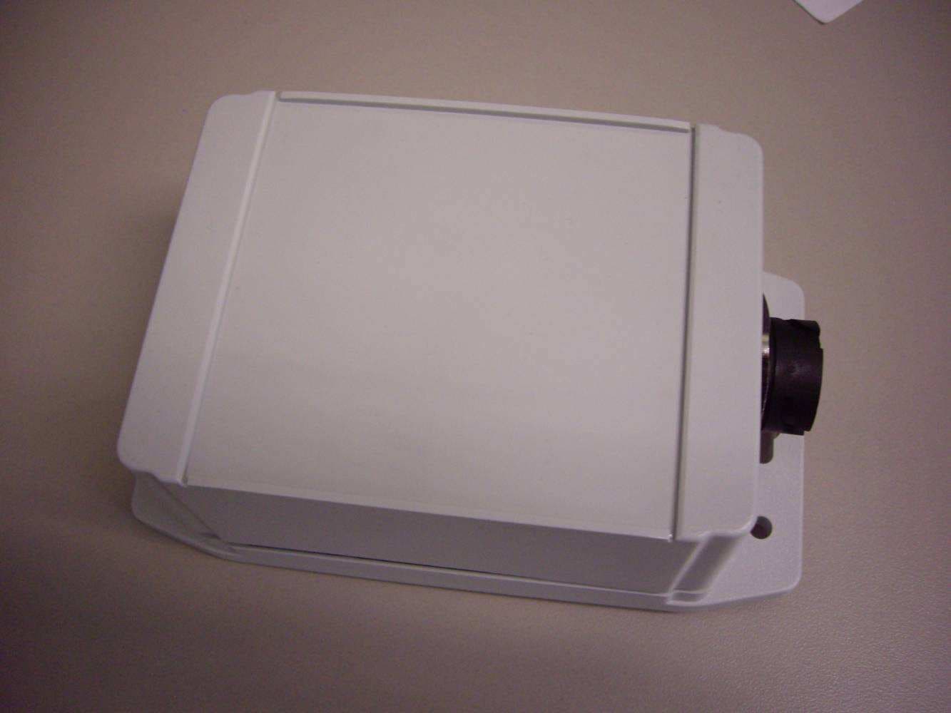
Click to zoom
Application Details
- Equipment Class
- DXX - Part 15 Low Power Communication Device Transmitter
- Date of Grant
- Feb 02, 2012
- Application Purpose
- Original Equipment
- Date of Application
- Feb 02, 2012
- Equipment Note
- Clarity Wireless Gateways
- Frequency Range
- 2405.00000000 - 2475.00000000
- Country
- United States
Documents & Files
Document Text
Text extracted from the exhibit documents filed with the FCC. Open a document above to read the original.
Users Manual
Installation and Operations Manual for Clarity Monitors – SPM80V12A, SPM80V12A-S SPM125V8A, SPM125V8A-S Clarity Site Server – SPS1 Clarity Gateway – SPG1 Clarity Disable Switch – SPD1 Solar Power Technologies, Inc. 3006 Bee Caves Road, Suite A-330 Austin, TX 78646 512.782.8957 800.349.6976 (800.fix.mysolar) www.spowertech.com [email protected] Table of Contents Section 1 – Important Safety Instructions/Read this First Section 2 – Product Compliance Information Section 3 – Product and Technology Overview Section 4 – Intelligent Array Definition Section 5 – Site Server, Wireless Gateway and Sensor Installation Section 6 – Panel Monitor Installation Section 7 – Array Commissioning and Inverter Start Section 8 – Troubleshooting Site Server and Gateway Section 9 – Monitor Technical Specifications Section 10 – Monitor Warranty Section 1– Important Safety Instructions/Read this First PLEASE SAVE THESE IMPORTANT SAFETY INSTRUCTIONS This manual contains important instructions for the installation, commissioning, operations and maintenance of Solar Power Technologies, Inc. (SPTI) Clarity Monitors: SPM80V12A; SPM80V12A-S; SPM125V8A; SPM125V8A-S; and related support equipment. Please read thoroughly before attempting installation. • Only qualified personnel should install, replace or service the Clarity Monitors. SPTI will not be liable for loss or damage due to improper installation or misuse. • Tampering with or opening the Monitor, Gateway, Disable Switch or Site Server creates an electrical shock risk and will void the warranty. Do not attempt repair, these units contains no user-serviceable parts. • Do not connect or disconnect the Monitors while under load: both DC and AC power must be disconnected from the PV system inverter before installation or servicing. To further ensure safety, it is highly recommended that all combiner box fuses be removed, prior to Monitor installation. • When unloaded, both the Monitor and its adjacent PV panel still present a shock risk: note that the Monitor’s output voltage will be as high as the PV panel’s open circuit voltage (Voc) and any terminal may be as high as 1000V with respect to ground, depending on site design and wiring connections • Under extreme environmental conditions, a photovoltaic panel may produce higher short-circuit currents and/or higher open-circuit voltages than specified by the panel’s nameplate Standard Test Condition (STC) rating. Accordingly, these higher values of Isc and Voc should be utilized when determining compatibility with the Monitor’s maximum current and maximum voltage specifications. • Electrical installations must be carried out in accordance with all local electrical codes; the National Electrical Code (NEC), ANSI/NFPA 70; and with any other codes and regulations applicable to your installation site. • Refer to Section 9 of this document for Warranty Terms and Conditions. Contact SPTI customer service at [email protected] for return approval and RMA number. Section 2 - Product Compliance Information Safety The SPM80V12A, SPM80V12A-S, SPM125V8A, SPM125V8A-S, SPG-1 and SPD-1 are currently undergoing certification to the appropriate and applicable sections of the following International Standards: • UL 60950-1: UL Standard for Safety Information Technology Equipment – Part 1: General Requirements • CSA C22.2#60950-1 Information Technology Equipment Safety Part 1: General Requirements-First Edition; IEC 60950-1:2001, MOD; UL60950-1; Update 1; Update No2: 07/2006 • IEC 60950 : Issued 1991/09/01 Ed:2 Safety of Information Technology Equipment, Including Electrical Business Equipment Amendment 1-1992; Amendment 2-1993; Amendment 3-1995; Amendment 4-1996 All versions of the Monitor, SPG-1 and SPD-1 enclosures are watertight and comply with the NEMA 4 / IP 65 environmental enclosure rating standard. FCC Part 15 Compliance This equipment has been tested and found to comply with the following requirements • FCC 47CFR Part 15.247 Operation within the bands 902-928 MHz, 2400- 2483.5MHz and 5725-5850 MHz • FCC 47 CFR 15B Class B verification • ETSI EN 300 328 ; Issued 2007/01/09 V1.7.1 Electromagnetic compatibility and radio spectrum matters (ERM); Wideband transmission sys; data transmission equipment operating in the 2.4 GHz ISM band & using wideband modulation techniques; Harmonized EN Article 3.2 • ETSI EN 301 489-1; Issued 2008/04/01 V1.8.1 Electromagnetic compatibility and radio spectrum matters (ERM); Electromagnetic compatibility (EMC) standard for radio equipment and services; Part 1: Common technical requirements • ETSI EN 301 489-17; Issued 2009/05/12 Electromagnetic compatibility and radio spectrum matters (ERM); Electromagnetic compatibility (EMC) standard for radio equipment; Part 17: Specific conditions for broadband data transmission systems – V2.1.1 This device complies with part 15 of the FCC Rules. Operation is subject to the following two conditions: (1) This device may not cause harmful interference, and (2) this device must accept any interference received, including interference that may cause undesired operation. This equipment has been tested and found to comply with the limits for a Class B digital device, pursuant to part 15 of the FCC Rules. These limits are designed to provide reasonable protection against harmful interference in a residential installation. This equipment generates, uses and can radiate radio frequency energy and, if not installed and used in accordance with the instructions, may cause harmful interference to radio communications. However, there is no guarantee that interference will not occur in a particular installation. If this equipment does cause harmful interference to radio or television reception, which can be determined by turning the equipment off and on, the user is encouraged to try to correct the interference by one or more of the following measures: • Reorient or relocate the receiving antenna. • Increase the separation between the equipment and the receiver. • Conn…
Text truncated - open the document above for the full version.
External Photos
External Photographs FCC ID: ZRV-SPG IC ID: 9977A-SPG Model Number: SPG1 Model Number: SPD1 Model Numbers: SPG1& SPD1
ID Label/Location Info
Label base material – FlexCON DPM Poly White Sheet (2.0 mil polyester), including pressure-sensitive acrylic adhesive; UL-recognized and CSA-accepted, Label ink – UV-resistant ink, Label over-laminate material – ACPO 691V (1.0 mil UV-resistant polyester). Label base material – FlexCON DPM Poly White Sheet (2.0 mil polyester), including pressure-sensitive acrylic adhesive; UL-recognized and CSA-accepted, Label ink – UV-resistant ink, Label over-laminate material – ACPO 691V (1.0 mil UV-resistant polyester).
Test Report
EMC Report for Solar Power Technologies on the Clarity Wireless Gateways File: 100529795MPK-004 Page 1 of 65 TEST REPORT Report Number: 100529795MPK-004 Project Number: G100529795 Report Date: November 28, 2011 Testing performed on the Clarity Wireless Gateways Model Numbers: SPG1 & SPD1 FCC ID: ZRV-SPG IC ID: 9977A-SPG to FCC Part 15.247 and RSS-210 Issue 8 for Solar Power Technologies Test Performed by: Test Authorized by: Intertek 1365 Adams Court Menlo Park, CA 94025 USA Solar Power Technologies 3006 Bee Caves Road, Suite A330 Austin, TX 78746 USA Prepared by: Date: November 28, 2011 Krishna K Vemuri Reviewed by: Date: November 28, 2011 Ollie Moyrong This report is for the exclusive use of Intertek's Client and is provided pursuant to the agreement between Intertek and its Client. Intertek's responsibility and liability are limited to the terms and conditions of the agreement. Intertek assumes no liability to any party, other than to the Client in accordance with the agreement, for any loss, expense or damage occasioned by the use of this report. Only the Client is authorized to copy or distribute this report and then only in its entirety. Any use of the Intertek name or one of its marks for the sale or advertisement of the tested material, product or service must first be approved in writing by Intertek. The observations and test results in this report are relevant only to the sample tested. This report by itself does not imply that the material, product, or service is or has ever been under an Intertek certification program. This report must not be used to claim product endorsement by A2LA, NIST nor any other agency of the U.S. Government. EMC Report for Solar Power Technologies on the Clarity Wireless Gateways File: 100529795MPK-004 Page 2 of 65 Report No. 100529795MPK-004 Equipment Under Test: Clarity Wireless Gateways Trade Name: Solar Power Technologies Model Nos.: SPG1 & SPD1 FCC ID: ZRV-SPG IC ID: 9977A-SPG Applicant: Solar Power Technologies Contact: Mr. Ray Burgess Address: 3006 Bee Caves Road, Suite A330 Austin, TX 78746 Country USA Tel. Number: (512) 560-5460 Email [email protected] Applicable Regulation: FCC Part 15, Subpart C and RSS-210 Issue 8 Test Site Location: ITS – Site 1 1365 Adams Drive Menlo Park, CA 94025 Date of Test: October 20 to November 22, 2011 We attest to the accuracy of this report: Krishna K Vemuri EMC Senior Staff Engineer Ollie Moyrong Engineering Manager EMC Report for Solar Power Technologies on the Clarity Wireless Gateways File: 100529795MPK-004 Page 3 of 65 TABLE OF CONTENTS 1.0 Introduction .................................................................................................................................... 4 1.1 Summary of Tests................................................................................................................ 5 2.0 General Description ....................................................................................................................... 6 2.1 Product Description............................................................................................................. 6 2.2 Related Submittal(s) Grants ................................................................................................ 6 2.3 Test Methodology ............................................................................................................... 7 2.4 Test Facility......................................................................................................................... 7 3.0 System Test Configuration ............................................................................................................ 8 3.1 Support Equipment ............................................................................................................. 8 3.2 Block Diagram of Test Setup .............................................................................................. 9 3.3 Justification ....................................................................................................................... 10 3.4 Software Exercise Program ............................................................................................... 10 3.5 Mode of Operation During Test ........................................................................................ 10 3.6 Modifications Required for Compliance ........................................................................... 10 4.0 Measurement Results................................................................................................................... 11 4.1 Conducted Output Power at Antenna Terminals ............................................................... 11 4.2 6-dB Bandwidth ................................................................................................................ 15 4.3 Out-of-Band Conducted Emissions ................................................................................... 19 4.4 Power Spectral Density ..................................................................................................... 20 4.5 Transmitter Radiated Emissions........................................................................................ 24 4.6 Radiated Emissions from Digital Parts and Receiver ........................................................ 46 4.7 AC Line Conducted Emission........................................................................................... 62 5.0 RF Exposure Evaluation ............................................................................................................. 63 6.0 List of Test Equipment ................................................................................................................ 64 7.0 Document History ........................................................................................................................ 65 EMC Report for Solar Power Technologies on the Clarity Wireless Gateways File: 100529795MPK-…
Text truncated - open the document above for the full version.
Test Setup Photos
Setup Photographs FCC ID: ZRV-SPG IC ID: 9977A-SPG Radiated Emissions (Transmitter spurious) Radiated Emissions (Transmitter spurious) Radiated Emissions (Receiver spurious and Digital Parts) Radiated Emissions (Receiver spurious and Digital Parts) AC Line Conducted Emissions AC Line Conducted Emissions
Contact Information
Applicant
Ray Burgess(President & CEO)
Technical Contact
Solar Power Technologies IncRay A Burgess
[email protected](512) 782-8957
3006 Bee Caves Road · Austin · United States
Non-Technical Contact
Solar Power Technologies IncRay A Burgess
[email protected](512) 782-8957
Test Firm
IntertekTesting Services NA Inc.Charles Parker
Technical Specifications
| # | Rule Parts | Frequency Range | Power Output |
|---|---|---|---|
| 1 | 15C | 2.40 GHz - 2.48 GHz | 15.00 µW |
Other Applications from Solar Power Technologies Incorporated
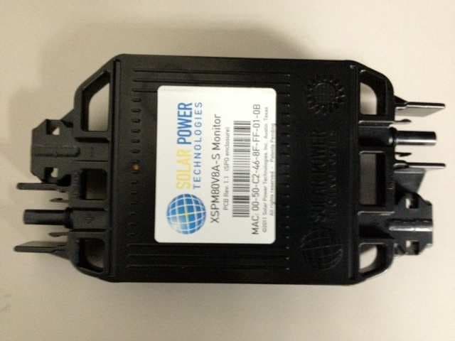
ZRV-SPO
Feb 27, 2012Clarity Optimizer
Equipment Class
DTS - Digital Transmission System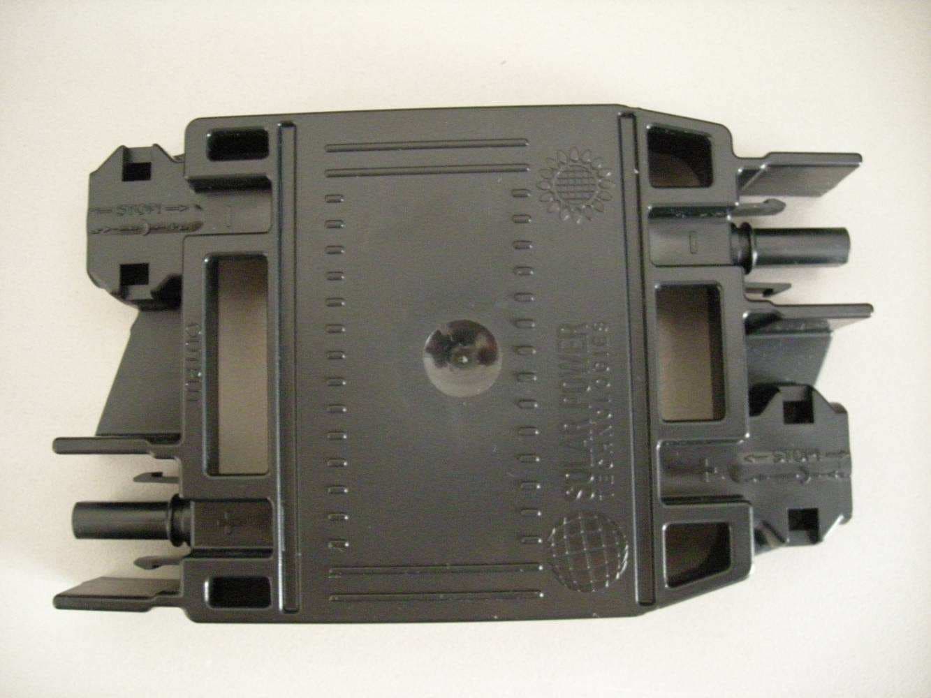
ZRV-SPM
Feb 02, 2012Clarity Monitors
Equipment Class
DXX - Part 15 Low Power Communication Device Transmitter