ZRV-SPOClarity Optimizer
Solar Power Technologies Incorporated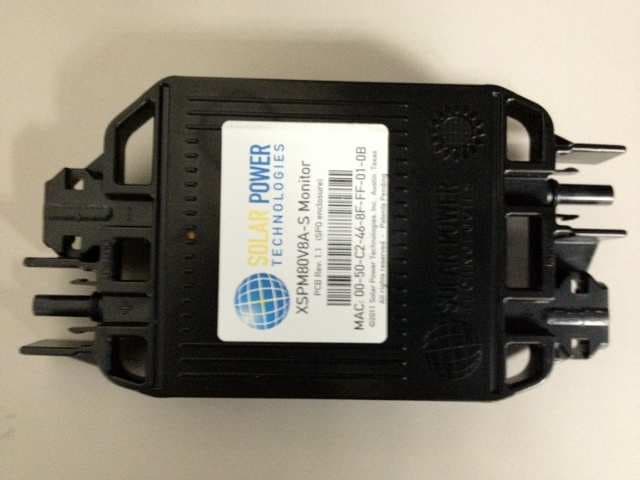
Click to zoom
Application Details
- Equipment Class
- DTS - Digital Transmission System
- Date of Grant
- Feb 27, 2012
- Application Purpose
- Original Equipment
- Date of Application
- Feb 27, 2012
- Equipment Note
- Clarity Optimizer
- Frequency Range
- 2405.00000000 - 2475.00000000
- Country
- United States
Documents & Files
Document Text
Text extracted from the exhibit documents filed with the FCC. Open a document above to read the original.
Users Manual
Installation & Operations Manual Clarity™ System Clarity™ Site Server – SPS1 Clarity™ Gateway – SPG1; SPD1 Clarity™ Nodes: • SPM80V12A • SPM80V12A-S • SPM125V8A • SPM125V8A-S • SPO350W80V “Bringing Clarity to Solar Power Generation” CAUTION RISK OF ELECTRICAL SHOCK REFER SERVICING TO QUALIFIED SERVICE PERSONNEL Caution To reduce risk of electrical shock, do not perform any servicing other than that contained in the Installation and Troubleshooting Instructions unless you are qualified to do so. Refer all servicing to qualified service personnel. Special Symbols That Might Appear on the Equipment and in this Manual Danger This symbol indicates that dangerous voltage levels are present within the system. These voltages are not insulated and may be of sufficient strength to cause fatal, or serious bodily injury when touched. The symbol may also appear on schematics. Warning The exclamation point, within an equilateral triangle, is intended to alert the user to the presence of important installation, servicing, and operating instructions in the documents accompanying the equipment. Caution The exclamation point, within an equilateral triangle, is intended to alert the user to the presence of important installation, servicing, and operating instructions in the documents accompanying the equipment. Important Information Accompanies notes that call attention to supplementary information that you must know and use to ensure optimal operation of the system. IMPORTANT SAFETY INSTRUCTIONS SAVE THESE INSTRUCTIONS This manual contains important instructions for the Clarity™ System, and should be followed during the installation and maintenance of the system. Please read thoroughly before attempting installation. Danger To reduce risk of electrical shock, do not open a Monitor, Optimizer, Gateway, Disable Switch, or Site Server. Do not attempt repair. There are no user-serviceable parts inside. Danger When unloaded, Monitors, Optimizers, and their attached PV panels still present a shock risk. Note that the Monitor or Optimizer output voltage will be as high as the PV panel’s open circuit voltage (Voc), and any electrical terminal on a monitor may be as high as 1000V with respect to ground, depending on site design and wiring connections Warning Do not connect or disconnect a Monitor or Optimizer while under electrical load: DC power and AC power must be disconnected from the PV system inverter before installing or servicing Monitors. Warning To ensure safety, all combiner box fuses must be opened prior to altering any Monitor or Optimizer electrical connections. Warning Under extreme environmental conditions, a photovoltaic panel may produce higher short-circuit currents and/or higher open-circuit voltages than specified by the panel’s nameplate Standard Test Condition (STC) rating. Accordingly, these higher values of Isc and Voc should be utilized when determining compatibility with the Monitor or Optimizer maximum current and maximum voltage specifications. Warning String fuses must be present elsewhere in the system. Clarity™ Monitors and Optimizers do not include string fuses, or any form of over- current protection Warning The Clarity system does not provide any protection from ground faults or arc faults. Where required, protection from ground faults and arc faults must be provided elsewhere in the system. Caution Monitors, Optimizers, Gateways, Disable Switches, and Site Servers are designed to be installed outdoors. However, electrical connections to these products should be made and altered only under dry weather conditions. Every effort should be made to avoid getting dirt and moisture into electrical connections before they are mated and properly sealed. Moisture in electrical connections can present a shock hazard, and can also accelerate corrosion. Warning This equipment operates over the marked Voltage and Frequency range without requiring manual setting of any selector switches. Different types of line cord sets may be used for connections to the mains supply circuit and should comply with the electrical code requirements of the country of use. The line cord provided with the equipment is acceptable for use with NEMA Style 5-15R AC receptacles supplying nominal 120 Volts. iii FCC Compliance The SPM80V12A, SPM80V12A-S, SPM125V8A, SPM125V8A-S, SPG1, SPD1 and SPS1 have been tested and found to comply with the following requirements: • FCC 47CFR Part 15.247 Operation within the bands 902-928 MHz, 2400-2483.5MHz and 5725-5850 MHz • FCC 47 CFR 15B Class B verification • ETSI EN 300 328 ; Issued 2007/01/09 V1.7.1 Electromagnetic compatibility and radio spectrum matters (ERM); Wideband transmission system; data transmission equipment operating in the 2.4 GHz ISM band & using wideband modulation techniques; Harmonized EN Article 3.2 • ETSI EN 301 489-1; Issued 2008/04/01 V1.8.1 Electromagnetic compatibility and radio spectrum matters (ERM); Electromagnetic compatibility (EMC) standard for radio equipment and services; Part 1: Common technical requirements • ETSI EN 301 489-17; Issued 2009/05/12 Electromagnetic compatibility and radio spectrum matters (ERM); Electromagnetic compatibility (EMC) standard for radio equipment; Part 17: Specific conditions for broadband data transmission systems – V2.1.1 • These devices comply with part 15 of the FCC Rules. Operation is subject to the following two conditions: • These devices may not cause harmful interference. • These devices must accept any interference received, including interference that may cause undesired operation. These devices have been tested and found to comply with the limits for a Class B digital device, pursuant to part 15 of the FCC Rules. These limits are designed to provide reasonable protection against harmful interference in a residential installation. This equipment generates uses and can radiate radio frequency energy and, if not installed and used in accordance with the instructions, may cause harmful interference to radio comm…
Text truncated - open the document above for the full version.
External Photos
External Photographs FCC ID: ZRV-SPO IC ID: 9977A-SPO
ID Label/Location Info
SPO
Test Report
EMC Report for Solar Power Technologies on the Clarity Optimizer File: 100529787MPK-004 Page 1 of 65 TEST REPORT Report Number: 100529787MPK-004 Project Number: G100529787 Report Date: February 03, 2012 Testing performed on the Clarity Optimizer Model Number: SPO350W80V FCC ID: ZRV-SPO IC: 9977A-SPO to FCC Part 15 Subpart C (15.247) RSS-210 Issue 8 FCC Part 15, Subpart B Industry Canada ICES-003 for Solar Power Technologies Test Performed by: Test Authorized by: Intertek 1365 Adams Court Menlo Park, CA 94025 USA Solar Power Technologies 3006 Bee Caves Road, Suite A330 Austin, TX 78746, USA Prepared by: Date: February 03, 2012 Krishna K Vemuri Reviewed by: Date: February 03, 2012 Ollie Moyrong This report is for the exclusive use of Intertek's Client and is provided pursuant to the agreement between Intertek and its Client. Intertek's responsibility and liability are limited to the terms and conditions of the agreement. Intertek assumes no liability to any party, other than to the Client in accordance with the agreement, for any loss, expense or damage occasioned by the use of this report. Only the Client is authorized to copy or distribute this report and then only in its entirety. Any use of the Intertek name or one of its marks for the sale or advertisement of the tested material, product or service must first be approved in writing by Intertek. The observations and test results in this report are relevant only to the sample tested. This report by itself does not imply that the material, product, or service is or has ever been under an Intertek certification program. This report must not be used to claim product endorsement by A2LA, NIST nor any other agency of the U.S. Government. EMC Report for Solar Power Technologies on the Clarity Optimizer File: 100529787MPK-004 Page 2 of 65 Report No. 100529787MPK-004 Equipment Under Test: Clarity Optimizer Trade Name: Solar Power Technologies Model No.: SPO350W80V FCC ID: ZRV-SPO IC: 9977A-SPO Applicant: Solar Power Technologies Contact: Mr. Ray Burgess Address: 3006 Bee Caves Road, Suite A330 Austin, TX 78746 Country USA Tel. Number: (512) 560-5460 Email [email protected] Applicable Regulation: FCC Part 15 Subpart C (15.247) RSS-210 Issue 8 FCC Part 15, Subpart B Industry Canada ICES-003 Test Site Location: ITS – Site 1 1365 Adams Drive Menlo Park, CA 94025 Date of Test: January 09 to February 03, 2012 We attest to the accuracy of this report: Krishna K Vemuri EMC Senior Staff Engineer Ollie Moyrong Engineering Manager EMC Report for Solar Power Technologies on the Clarity Optimizer File: 100529787MPK-004 Page 3 of 65 TABLE OF CONTENTS 1.0 Introduction .................................................................................................................................... 4 1.1 Summary of Tests................................................................................................................ 5 2.0 General Description ....................................................................................................................... 6 2.1 Product Description............................................................................................................. 6 2.2 Related Submittal(s) Grants ................................................................................................ 6 2.3 Test Methodology ............................................................................................................... 7 2.4 Test Facility......................................................................................................................... 7 3.0 System Test Configuration ............................................................................................................ 8 3.1 Support Equipment ............................................................................................................. 8 3.2 Block Diagram of Test Setup .............................................................................................. 9 3.3 Justification ....................................................................................................................... 10 3.4 Software Exercise Program ............................................................................................... 10 3.5 Mode of Operation During Test ........................................................................................ 10 3.6 Modifications Required for Compliance ........................................................................... 10 4.0 Measurement Results................................................................................................................... 11 4.1 Conducted Output Power at Antenna Terminals ............................................................... 11 4.2 6-dB Bandwidth ................................................................................................................ 15 4.3 Out-of-Band Conducted Emissions ................................................................................... 19 4.4 Power Spectral Density ..................................................................................................... 20 4.5 Transmitter Radiated Emissions........................................................................................ 24 4.6 Radiated Emissions from Receiver.................................................................................... 46 4.7 Radiated Emissions from Digital Parts.............................................................................. 52 4.8 AC Line Conducted Emission........................................................................................... 58 5.0 RF Exposure Evaluation ............................................................................................................. 63 6.0 List of Test Equipment ................................................................................................................ 64 7.0 Document History ......................…
Text truncated - open the document above for the full version.
Test Setup Photos
Setup Photographs FCC ID: ZRV-SPO IC ID: 9977A-SPO Radiated Emissions Radiated Emissions AC Line Conducted Emissions AC Line Conducted Emissions
Contact Information
Applicant
Ray Burgess(President & CEO)
Test Firm
Intertek Testing Services NA Inc.John Quigley
Technical Specifications
| # | Rule Parts | Frequency Range | Power Output |
|---|---|---|---|
| 1 | 15C | 2.40 GHz - 2.48 GHz | 25.70 µW |
Other Applications from Solar Power Technologies Incorporated
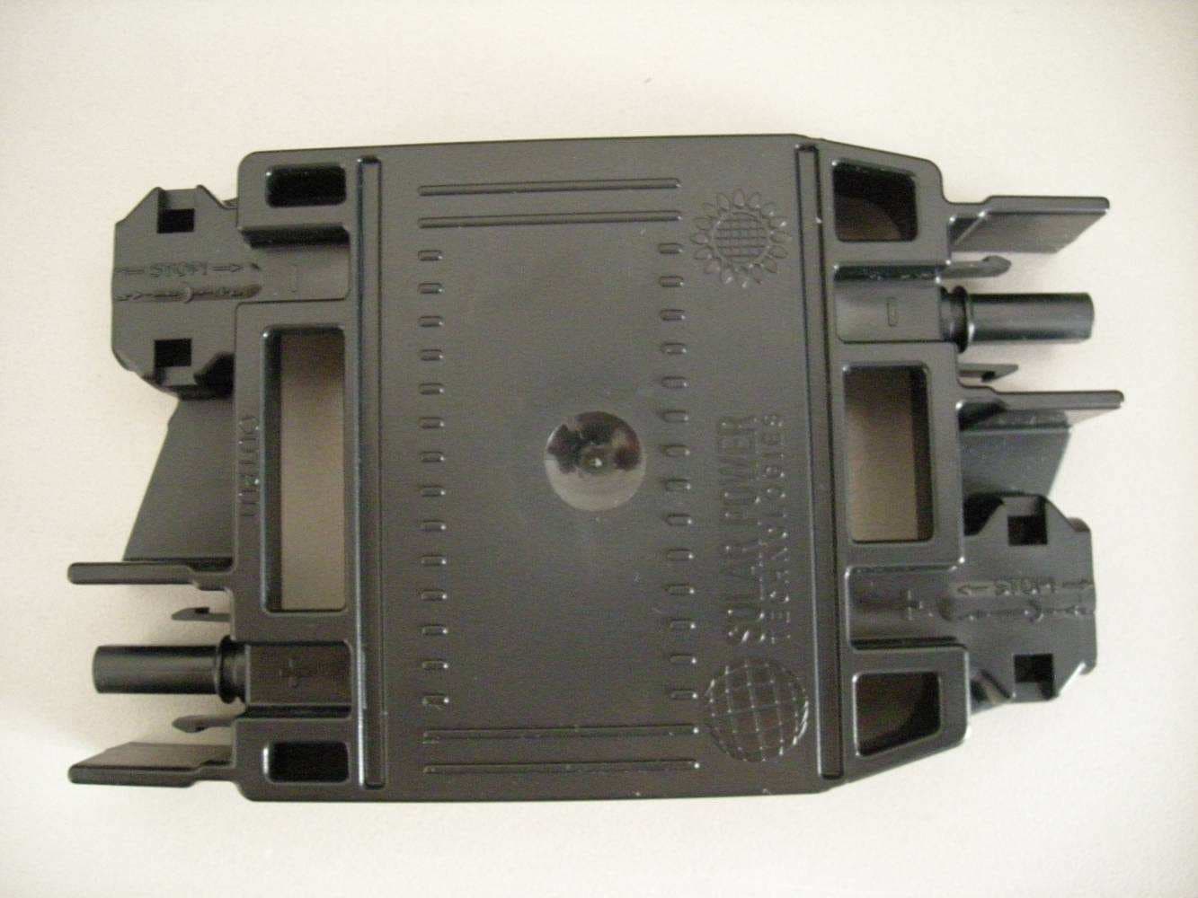
ZRV-SPM
Feb 02, 2012Clarity Monitors
Equipment Class
DXX - Part 15 Low Power Communication Device Transmitter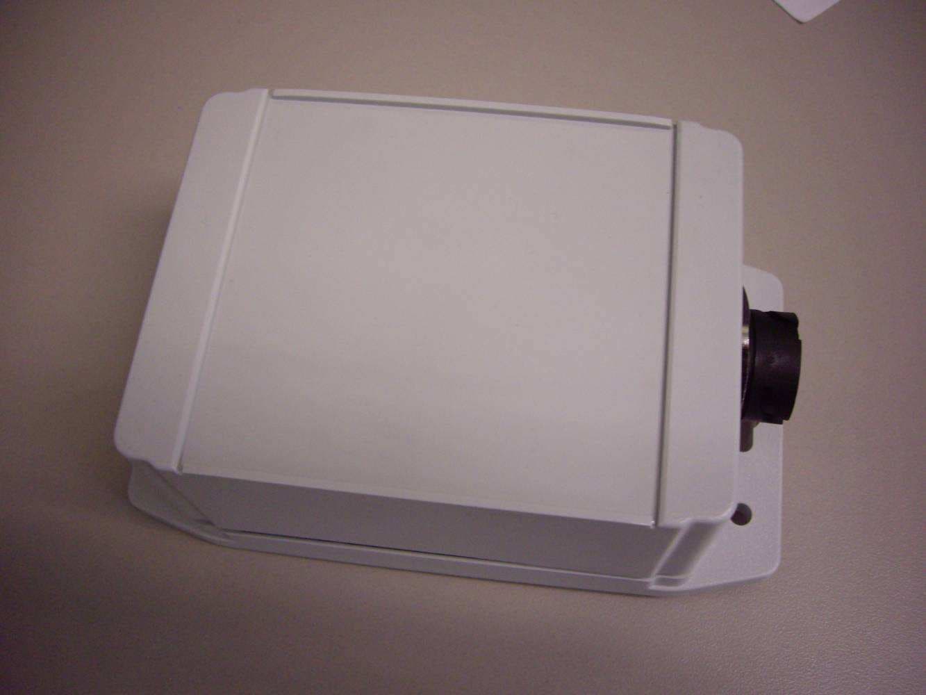
ZRV-SPG
Feb 02, 2012Clarity Wireless Gateways
Equipment Class
DXX - Part 15 Low Power Communication Device Transmitter