ZRY923Spread Spectrum Transmitter
Andon Health Co., Ltd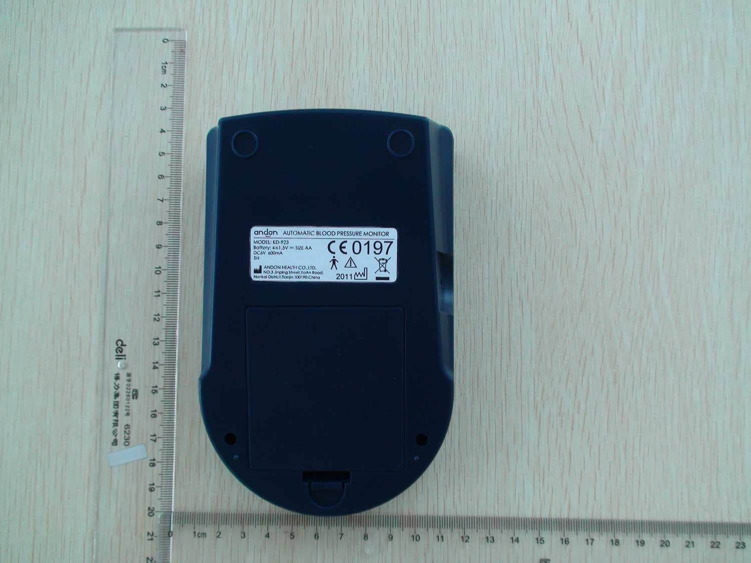
Click to zoom
Application Details
- Equipment Class
- DSS - Part 15 Spread Spectrum Transmitter
- Date of Grant
- Sep 17, 2011
- Application Purpose
- Original Equipment
- Date of Application
- Sep 13, 2011
- Equipment Note
- Spread Spectrum Transmitter
- Frequency Range
- 2402.00000000 - 2480.00000000
- Company
- Andon Health Co., Ltd
- Country
- China
Documents & Files
Document Text
Text extracted from the exhibit documents filed with the FCC. Open a document above to read the original.
Users Manual
INSTRUCTION MANUAL Model PLEASEREAD BEFORE USE EasyandAff or dableSolutions forBetterHealth™ M A N A G E M E N T S Y S T E M Blood Pressure BP-Manager ™ *NOTE: The system is intended for information purposes only, for expert advice make sure to consult a healthcare professional. Any instructions for change in treatment and health related information or advice should only be made directly with a healthcare professional. The ANDON BP-MANAGER™ is a non-invasive blood pressure monitor intended for the measurement of systolic (SBP) and diastolic (DBP) blood pressure and heart rate (HR or pulse rate) using the oscillometric technique. The ANDON BP-MANAGER™ is used as an aid to monitoring blood pressure in adults (individuals aged 18 and older) in a non-clinical environment such as in the home. Results are displayed on the ANDON BP-MANAGER™ screen. The ANDON BP-MANAGER™ should not be used on infants or children. Contraindications for Use: The end user of this device should not have common arrhythmias, such as atrial or ventricular premature beats or atrial fibrillation. Version 2.0 Jan 2009 *Picture may vary from actual product ANDON KD-923 BP-Manager™ 2 Table of Con ten ts Table of Con ten ts TABLEOF CONTENTS2 INTR ODUCTION3 CONTENTS4 REQUIREMENTS5 !W ARN INGS!6 Pod™ LOC ATION/INTERFERANCE7 BEFOREYOU ST AR T8 YourBP-Manager™8 YourI Pod™9 INST ALL ATION10 Connecting Your Pod™10 Using an RJ11Jack10 Back-upBatt er ies11 Power ing Up Your BP-Manager™11 First Time Power Up and Registration12 SUGGESTIONSBEFORE TAKING A MEASUREMENT13 HO W TO APPL Y THE ARMCUFF13 Applyingthe Pressure Cuff14 HO W TO TAKE A PR OP ER MEASUREMENT15 FUNCTIONS16 Main Scr een16 Tak ing Your Blo od Pressure Measurement17 Error Displa y18 Look ing at Previously Tak en Readings19 Look ing at Messages20 Look ing at Graphics21 Users22 Selec t User22 Add/R emo ve User23 CARE ANDMAINTENANCE25 SPE CIFICATIONS26 BP-Manager™26 Pod™26 FC C ST ATEMENT27 CUSTOMERINFORMA TION28 SER VICEREQUIREMENTS29 ANDON ANDON ANDON ANDON ANDON ANDON ANDON ANDON In tr oduction Instruc tionManual 3 In tr oduction Pleaseread this instruction manualthor ou ghl y. For pr op er int erpr etation of pr essure measureme nts , mak e sur e to consulta phy sician. TheBP -M anager™can be usedaloneto aut omaticall y measure your blo od pr essure. If you would lik e to tr ansmit blo od pr essure information for display on a personalcomputer , the optionalPod™ can be pur chased. Instr uc tionsfor Use for theBP -M anager™and for thePod™ ar e includedin this Instruction manual. **W arning:This sy st em is not rec ommended for use on infantsand is not int endedfor and shouldnot be usedto tr y to measure the blo od pr essure of infantsand children (any one underthe age of 18) as it ma y not be accurat e and/orreliedup on . ANDON ANDON ANDONANDON Thank you for purchasing the ANDON BP-MANAGER™, or KD-923 and ANDON POD™, or ILP 0001. This completely automatic system measures your blood pressure and pulse rate, captures subjective information and manages everything automatically so that you can better manage your blood pressure with your care provider. Your measurement reading is clearly displayed on a large screen on the ANDON BP-Manager™ after each measurement, and later stored for a more detailed analysis in the form of tables for easy viewing and graphs for easy interpretation. Your new ANDON BP-Manager™ uses the oscillometric method of blood pressure measurement, detecting your blood’s movement through your brachial artery and converting the movements into a digital reading. An oscillometric monitor does not need a stethoscope so the monitor is simple to use. The ANDON KD-923 BP-Manager™ is a non-invasive blood pressure monitor intended for the measurement of systolic (SBP) and diastolic (DBP) blood pressure and heart rate (HR or pulse rate) using the oscillometric technique. The ANDON BP-Manager™ is used as an aid to monitoring blood pressure in adults (individuals aged 18 and older) in a non-clinical environment such as in the home. Results are displayed on the ANDON BP-Manager™ screen. The ANDON BP-Manager™ should not be used on infants or children. Contraindications for Use: The end user of this device should not have common arrhythmias, such as atrial or ventricular premature beats or atrial fibrillation. Contents BP -MANAGER™ 4X“AA”ALKALINE BATTERIES FOR YOUR BP-MANAGER™ ILP 0001POD™ (*Anoptional accessory, soldseparately) AC ADAPTER (*Anoptional accessory, soldseparately) TELEPHONELINE CORD (*Anoptional accessory, soldseparately) Contents BP-Manager™ 4 Sys Dia Pul 128 85 64 ANDON KD-923 ANDON ANDON ANDON For Respective Products, make sure your package includes the following items: Requirements Instruc tionManual 5 Requirements MODULARJA CKREQUIREMENTS ADDITIONAL BATTERIES When using your ANDON BP-Manager™ with an ANDON Pod™, you will need an RJ11 type modular jack, which is the most common type of phone jack and might look like the one pictured here. If you don’t have a modular jack, call your local phone company to find out how to get one installed. You may wish to use rechargeable batteries in your ANDON Manager™. The ANDON Pod™ is equipped to recharge batteries. !War nings! !War nings! BP-Manager™ 6 To assure the correct use of the product basic safety measures should always be followed including the precautions listed below: • Read all the information in the instruction manual and any other literature included in the box before using the unit. • Follow the instructions of your healthcare provider. • Contact your physician for specific information about your blood pressure. • Operate the unit only as intended. Do not use for any other purpose. • The ANDON KD-923 BP-Manager™ is a non-invasive blood pressure monitor intended for the measurement of systolic (SBP) and diastolic (DBP) blood pressure and heart rate (HR or pulse rate) using the oscillometric technique. The ANDON BP-Manager™ is used as an aid to monitoring blood pressure in adults (individuals aged 18 …
Text truncated - open the document above for the full version.
Block Diagram
Figure 1: KD-923 Blood pressure monitor frequency diagram Figure 2: BM30SPP01 Bluetooth Module Diagram Theory of operation : Collection of electronic blood pressure monitor blood pressure trough the manometer sensor signal into the A/D conversion , sent from the slave MCU operation , operation result is sent to the mastet MCU , and then tfansmitted via Bloodtooth. Blood pressure signal acquisition Slave MCU for signal processing The master MCU to accept the treatment of blood pressure signal 8MHz oscillator 11.0592MHz oscillator Bluetooth module 16MHz oscillator Center frequency 2.4GHz antenna for transmitting signal
External Photos
Photo Documentation Report Number: 15045012 001 Model: KD-923 - Page 1 of 1 - External photos
Internal Photos
Photo Documentation Report Number: 15045012 001 Model: KD-923 - Page 3 of 3 - Photo Documentation Report Number: 15045012 001 Model: KD-923 - Page 4 of 4 - Photo Documentation Report Number: 15045012 001 Model: KD-923 - Page 5 of 5 - Photo Documentation Report Number: 15045012 001 Model: KD-923 - Page 6 of 6 - Photo Documentation Report Number: 15045012 001 Model: KD-923 - Page 7 of 7 - Bluetooth module Photo Documentation Report Number: 15045012 001 Model: KD-923 - Page 8 of 8 -
Operational Description
KD-923 Blood pressure monitor frequency diagram Theory of operation : Collection of electronic blood pressure monitor blood pressure trough the manometer sensor signal into the A/D conversion , sent from the slave MCU operation , operation result is sent to the mastet MCU , and then tfansmitted via Bloodtooth. Blood pressure signal acquisition Slave MCU for signal processing The master MCU to accept the treatment of blood pressure signal 8MHz oscillator 11.0592MHz oscillator Bluetooth module 16MHz oscillator Center frequency 2.4GHz antenna for transmitting signal
RF Exposure Info
FCC ID: ZRY 923 Produkte Products RF Exposure Statement: 15045157 001 Page 1 of 1 Client: Andon Health Co., Ltd. No.31 Changjiang Road, Nankai District Tianjin 300193, P.R. China Test item: Automatic Blood Pressure Monitor Identification: KD-923 FCC Requirement According to KDB 447498, SAR evaluation specified in FCC 2.1093 is not required for portable equipment if the transmitter power is below the following threshold: Tunable Range Lowest Frequency [GHz] Highest Frequency [GHz] Center of Tunable Band [GHz] 60/f SAR Limitation based on Center of Band [mW] 2.402 2.480 2.441 24.58 Measurement Result The maximum measured transmitter power is the following: Conducted Output Power P out [mW] Maximum Antenna Gain [dBi] P out EIRP [mW] 7.533 2.28 12.74 Conclusion SAR evaluation is not required since the maximum transmitter power P out (both conducted and e.i.r.p.) is below the FCC threshold. Refer to test report 15045157 001 for more details. TÜV Rheinland (Shanghai) Co., Ltd. 10-15/F, Huatsing Building, No.88, Lane 777, Guangzhong Road West, Shanghai 200072, P.R. China
Schematics
VDD DIS SD VWOUT VDDVCC GND +6V TXDRXD MASTER SLAVE EMERGENCY BPM_RES MCU_BPM 单元 MCU_BPM.sch C30.1uF R24 100K R25200K 1% 56 7 U4B LM324DR 10 9 8 U4C LM324DR 1213 14 U4DLM324DR R18 30K 1% R19 30K 1% R22 30K 1%R23 30K 1% VSR/VAR VIR 32 1 411 U4ALM324DR VCC VIR R4200R3160 VSR/VAR VIR R20 30K 1% R2130K 1% R14.7K VCC R10430 1% R324.7K +6V VCC 2 3 1 Q4 9015 C5 0.1uF +IN 3 +OUT 2 -OUT 5 -IN 6 -IN 1 NC 4 SEN KD-2107-006G R292.49K 1% R14100 R15100 R11100 R12100 JB1JP JB2JP R26100K 1 3 2 Q1 9014 +6V C20.1uF KD-923 电路原理图-电源、放大单元 R34100K C360.1uF C4147pF R27 20M C380.1uF R528.2K VCC VDD +6V 12 BATT BATT-6V R38470K C70.1uF R37470K TXDRXD BATT MASTERSLAVEEMERGENCYBPM_RES +6V VDDGND MCU 单元 MCU.sch CB3 33uF/10V C1010.47uF VEE Vin 3 Vout 2 GND 1 U5S-1206B33-M3T1 +6VVDD CB1 33uF/10V (NC) C1' 0.01uF (NC) R51 10K 1 32 Q109014 C4247pF Vin 3 Vout 2 GND 1 U2S-1206B36-M3T1 C52 0.47uF KD-923 KD923-T1S1.0-101218-SCH 3 臂式血压计 产品名称 第 页 产品型号 设计 审核 批准 日期 日期 日期 原理图编号 编号 1 版本 NO. 12 3 更 改 记 录 更改时间 V1.0 共 页 C1 0.01uF SD +6VVDDVCCGND +6VVDDVCC KD-923 电路原理图- MCU_BPM 单元 TXD RXD BPM_RES VDD R68 10K A0 1 A1 2 A2 3 GND 4 SDA 5 SCL 6 WP 7 VCC 8 U6K24C08 R67 10K VDD VDD SDASCL X1X2 SDA VDD C140.1uF SLAVE SCL SD 13 D31N4148 R60120 DIS R8062K MASTER DIS MET CW VDD R6510K X1 1 X2 2 GND 3 X1 CSTLS8M00G53 R891K R7120K R6910K +6V 12 VALVEVALVE R62100K R701K VDD 23 1 Q99015 VDD 1 32 Q7L8050 R7420K R7210K CW +6V 12 PUMPPUMP R73220 VDD 23 1 Q89015 1 32 Q6L8050 MET VALVE PUMP +6V R6110K P74/SEG11 34 P75/SEG10 35 P76/SEG9 36 COM3 37 COM2 38 COM1 39 COM0 40 VLC 41 P33(PDO/PWM6/PPG6/TC6) 42 P34/PDO5/PWM5/TC5 43 P37/DVO 44 VSS 1 XIN 2 XOUT 3 TEST 4 VDD 5 P21/XTIN 6 P22/XTOUT 7 RESET 8 P20/INT5/STOP 9 P61/ECIN/AIN1 10 P62/ECNT/AIN2 11 P63/AIN3/INT0 12 P64/AIN4/STOP2 13 P10/SEG31/RXD 14 P11/SEG30/TXD 15 P12/SEG29/INT1 16 P13/SEG28/INT2 17 P14/SEG27/INT3 18 P15/SEG26/SI 19 P16/SEG25/SO 20 P17/SEG24/SCK 21 P50/SEG23 22 P73/SEG12 33 P72/SEG13 32 P71/SEG14 31 P70/SEG15 30 P57/SEG16 29 P56/SEG17 28 P55/SEG18 27 P54/SEG19 26 P53/SEG20 25 P52/SEG21 24 P51/SEG22 23 U1 TMP86PH22UG EMERGENCY R6410K X2X1 C1312pFC1212pF VWOUT VWOUT C40.1uF TXD SLAVE RXD EMERGENCY MASTER BPM_RES R551M BPM_RES EMERGENCYSLAVETXDRXD MASTER KD-923 KD923-T1S1.0-101218-SCH 3 臂式血压计 产品名称 第 页 产品型号 设计 审核 批准 日期 日期 日期 原理图编号 编号 2 版本 NO. 12 3 更 改 记 录 更改时间 V1.0 共 页 +6VVDDGND +6VVDD KD-923 电路原理图- MCU 、蓝牙单元 XTAL1 XTAL2 R88 10K A0 1 A1 2 A2 3 GND 4 SDA 5 SCL 6 WP 7 VCC 8 U9AT24C512BN-SH-T R87 10K VDD VDD EEPROM_SDAEEPROM_SCL EEPROM_SDAEEPROM_SCL LCM_ENABLE KEY2 KEY3 KEY1 KEY2KEY3 R59100K R58100K R50100K S1 6D300g-1507 KEY1 X1 1 X2 2 GND 3 X2 11.0592MHz XTAL2XTAL1 BEEP P0.3/AD3 34 P0.2/AD2 35 P0.1/AD1 36 P0.0/AD0 37 VDD 38 P4.2/INT3 39 P1.0/AIN0/T2 40 P1.1/AIN1/T2EX/ECI 41 P1.2/AIN2/CEX1/S2RXD 42 P1.3/AIN3/CEX1/S2TXD 43 P1.4/AIN4/CEX2/SS 44 P1.5/AIN5/CEX3/MOSI 1 P1.6/AIN6/CEX4/MOSO 2 P1.7/AIN7/CEX5/SPICLK 3 RESET 4 P3.0/RXD 5 P4.3/INT2 6 P3.1/TXD 7 P3.2/INT0 8 P3.3/INT1 9 P3.4/T0CKO 10 P3.5/S2CKO/ALE/T1 11 WR/P3.6 12 RD/P3.7 13 XTAL2 14 XTAL1 15 VSS 16 P4.0 17 P2.0/A8/KBI0 18 P2.1/A9/KBI1 19 P2.2/A10/KBI2 20 P2.3/A11/KBI3 21 P2.4/A12/KBI4 22 P0.4/AD4 33 P0.5/AD5 32 P0.6/AD6 31 P0.7/AD7 30 V30 29 P4.1/ALE 28 ICE_SDA 27 ICE_SCL 26 P2.7/A15/KBI7 25 P2.6/A14/KBI6 24 P2.5/A13/KBI5 23 U7 MPC82G516A LCM_DATALCM_CLKRES C4' 470nF R56'100K VDD BT_TXDBT_RXDRTC_INT0RTC_INT1LCM_MODELCM_RESET S2 6D300g-1507 S3 6D300g-1507 BATT BATT R63 1K 1 32 Q159014 BEEPBCE-12095-5V +6V R100 120 C301uF C311uF C321uF C1122pFC1022pF VDD VDD C170.1uF C161uF C351uF C371uF C391uF C401uF C48 1uF C431uF C441uF C451uF C461uF P/S 1 C86 2 V0 3 V4 4 V3 5 V2 6 V1 7 CAP2- 8 CAP2+ 9 CAP1+ 10 CAP1- 11 CAP3+ 12 VOUT 13 VSS 14 VDD 15 D7/SL 16 D6/SCL 17 D5 18 D4 19 D3 20 D2 21 D1 22 D0 23 /RD(E) 24 /WR(RW) 25 A0 26 /RES 27 /CS1 28 LCMSDG096B66GPOGA LCM_DATA LCM_CLK LCM_MODE LCM_RESET LCM_ENABLE VEE CB833uF/10V VEE MASTER MASTER SLAVE RXD TXD RXD BPM_RES BPM_RES EMERGENCY EMERGENCY INT1 1 XOUT 2 XIN 3 VSS 4 VDD 8 SDA 7 SCL 6 INT2 5 U8S-35390A RTC_SCL RTC_SDA R90100K R91100K R92100K RTC_SDARTC_SCLRTC_INT1 R93100K VDD VDD RTC_INT0 X1 1 X2 2 GND 3 XT VT-200-F C345.1pF BGK R75 10K VEE 1 32 Q139014 BGK VSS 1 EAN 2 P00 3 P03 4 P31 5 HCI_RTS 6 HCI_CTS 7 P22 8 P11 9 P05 10 SAR_IN 11 P13 12 P12 13 HCI_TXD 14 HCI_RXD 15 VSS 32 USB_DP 16 USB_DM 17 P20 18 RST_N 19 P30 20 1V8 21 P24 22 P01 23 NC 24 NC 25 P17 26 BAT_DET 27 VDD1 28 VDD 29 VSS 30 BT_RF 31 COB BM30SPP01 LED1 LED1 TL-86R304LBC C330.1uF (兰) VEE' CB11 33uF/10V R97 120 L10 C47 0 BT_TXDBT_RXD VEE R99100K R10151K BT_CTL BT_RST BT_CTL BT_RST 12 BLLCD 背光(白色 ) VDD E1 CAN4311851042453K 12345678910 J4 MCU GNDVDD BPM_RESEMERGENCYRXDMASTER 123456789 10 J3BPM +6VTXDSLAVE SLAVE TXD VDD 1234 J1 KEY 1234 J2 KEY R94510 + CFXH414HG VEE' R571M 1 3 D5 SB02-03Q Q11 AP2305GN R490 C550.1uF(NC) 1234 J6DEBUG ICE_SDAICE_SCL GNDICE_SDAVDDICE_SCL KD-923 KD923-T1S1.0-101218-SCH 3 臂式血压计 产品名称 第 页 产品型号 设计 审核 批准 日期 日期 日期 原理图编号 编号 3 版本 NO. 12 3 更 改 记 录 更改时间 V1.0 共 页 R10210K
Test Report
FCC ID: ZRY923 Produkte Products Prüfbericht - Nr.: Test Report No.: 15045012 001 Seite 2 von 48 Page 2 of 48 TEST SUMMARY 3.2.1 VOLTAGE REQUIREMENTS, FCC 15.31(E) RESULT: PASS 3.2.2 ANTENNA REQUIREMENTS, FCC 15.203 AND FCC 15.204 RESULT: PASS 5.1.1 CONDUCTED OUTPUT POWER, FCC 15.247(B)(1) RESULT: PASS 5.1.2 CARRIER FREQUENCY SEPARATION, FCC 15.247(A)(1) RESULT: PASS 5.1.3 20DB BANDWIDTH, FCC 15.247(A)(1) 5.1.4 NUMBER OF HOPPING FREQUENCIES, FCC 15.247(A)(1)(III) RESULT: PASS 5.1.5 AVERAGE TIME OF OCCUPANCY, FCC 15.247(A)(1)(III) RESULT: PASS 5.1.6 CONDUCTED SPURIOUS EMISSION, FCC 15.247(D) RESULT: PASS 5.1.7 BAND EDGE COMPLIANCE OF RF CONDUCTED EMISSION, FCC 15.247(D) RESULT: PASS 6.1.1 BAND EDGE RADIATED EMISSION, FCC 15.205, FCC 15.209 AND FCC 15.247(D) RESULT: Pass 6.1.2 RADIATED SPURIOUS EMISSION OF TRANSMITTER, FCC 15.205, FCC 15.209 AND FCC 15.247(D) RESULT: PASS 6.2.1 RADIATED SPURIOUS EMISSION OF RECEIVER, FCC 15.109 RESULT: PASS FCC ID: ZRY923 Produkte Products Prüfbericht - Nr.: Test Report No.: 15045012 001 Seite 3 von 48 Page 3 of 48 Contents 1. GENERAL REMARKS............................................................................................... 5 1.1 COMPLEMENTARY MATERIALS................................................................................. 5 2. TEST SITES............................................................................................................ 5 2.1 TEST FACILITIES..................................................................................................... 5 2.2 LIST OF TEST AND MEASUREMENT INSTRUMENTS...................................................... 6 2.3 MEASUREMENT UNCERTAINTY................................................................................. 6 3. GENERAL PRODUCT INFORMATION........................................................................... 7 3.1 PRODUCT FUNCTION AND INTENDED USE.................................................................. 7 3.2 SYSTEM DETAILS.................................................................................................... 7 3.2.1 Voltage Requirements, FCC 15.31(e).......................................................................................... 7 3.2.2 Antenna Requirements, FCC 15.203 and FCC 15.204 ............................................................... 7 3.3 INDEPENDENT OPERATION MODES........................................................................... 8 3.4 CLOCK FREQUENCIES............................................................................................. 8 3.5 NOISE SUPPRESSING PARTS.................................................................................... 8 4. TEST SET-UP AND OPERATION MODES..................................................................... 9 4.1 TEST METHODOLOGY.............................................................................................. 9 4.2 PHYSICAL CONFIGURATION FOR TESTING................................................................. 9 4.3 TEST OPERATION AND TEST SOFTWARE................................................................... 9 4.4 SPECIAL ACCESSORIES AND AUXILIARY EQUIPMENT................................................. 9 4.5 COUNTERMEASURES TO ACHIEVE EMC COMPLIANCE................................................ 9 5 . TEST RESULTS OF CONDUCTED MEASUREMENTS AT ANTENNA PORT....................... 10 5.1 TRANSMITTER PARAMETERS.................................................................................. 10 5.1.1 Conducted Output Power, FCC 15.247(b)(1) ............................................................................ 10 5.1.2 Carrier Frequency Separation, FCC 15.247(a)(1) ..................................................................... 12 5.1.3 20dB Bandwidth, FCC 15.247(a)(1)........................................................................................... 15 5.1.4 Number of Hopping Frequencies, FCC 15.247(a)(1)(iii)............................................................ 19 5.1.5 Average Time of Occupancy, FCC 15.247(a)(1)(iii) .................................................................. 22 5.1.6 Conducted Spurious Emission, FCC 15.247(d) ......................................................................... 28 5.1.7 Band Edge Compliance of RF Conducted Emission, FCC 15.247(d) ....................................... 34 6. TEST RESULTS OF RADIATED MEASUREMENTS....................................................... 37 6.1 TRANSMITTER PARAMETERS.................................................................................. 37 6.1.1 Band Edge Radiated Emission, FCC 15.205, FCC 15.209 and FCC 15.247(d) ....................... 37 6.1.2 Radiated Spurious Emission of Transmitter, FCC 15.205, FCC 15.209 and FCC 15.247(d) ... 41 6.2 RECEIVER PARAMETERS....................................................................................... 43 6.2.1 Radiated Spurious Emission of Receiver, FCC 15.109 ............................................................. 43 FCC ID: ZRY923 Produkte Products Prüfbericht - Nr.: Test Report No.: 15045012 001 Seite 4 von 48 Page 4 of 48 7. PHOTOGRAPHS OF THE TEST SETUP....................................................................... 45 8. LIST OF TABLES.................................................................................................... 47 9. LIST OF FIGURES.................................................................................................. 47 10. LIST OF PHOTOGRAPHS......................................................................................... 48 FCC ID: ZRY923 Produkte Products Prüfbericht - Nr.: Test Report No.: 15045012 001 Seite 5 von 48 Page 5 of 48 1. General Remarks 1.1 Complementary Materials All attachments are integral parts of this test report. 2. Test Sites 2.1 Test Facilities TÜV Rheinland (Shanghai) Co., Ltd. 10-15/F, Huatsing Building, No.88, Lane 777, West Guangzhong Road, Zhabei District Shanghai 200072, P.R. China The …
Text truncated - open the document above for the full version.
Test Setup Photos
FCC ID: ZRY923 Produkte Products Prüfbericht - Nr.: Test Report No.: 15045012 001 Seite 45 von 48 Page 45 of 48 7. Photographs of the Test Setup Photograph 1: Set-up for Conducted Emissions at Antenna Port Photograph 2: Maximum emission orientation of the sample on the table FCC ID: ZRY923 Produkte Products Prüfbericht - Nr.: Test Report No.: 15045012 001 Seite 46 von 48 Page 46 of 48 Photograph 3: Set-up for Set-up for Radiated Emission, 30MHz-1000MHz Photograph 4: Set-up for Radiated Emission, 1G-18GHz
Contact Information
Applicant
Ming Cong(PM)
Technical Contact
TUV Rheinland (Shanghai) Co., Ltd.Xiangming Kong
[email protected]86-21-61081034
TUV Rheinland Building, No. 177, Lane 777 · Shanghai · China
Test Firm
TUV Rheinland (Shanghai) Co., Ltd.Xinhua LU
Technical Specifications
| # | Rule Parts | Frequency Range | Power Output |
|---|---|---|---|
| 1 | 15C | 2.40 GHz - 2.48 GHz | 7.53 mW |
Other Applications from Andon Health Co., Ltd
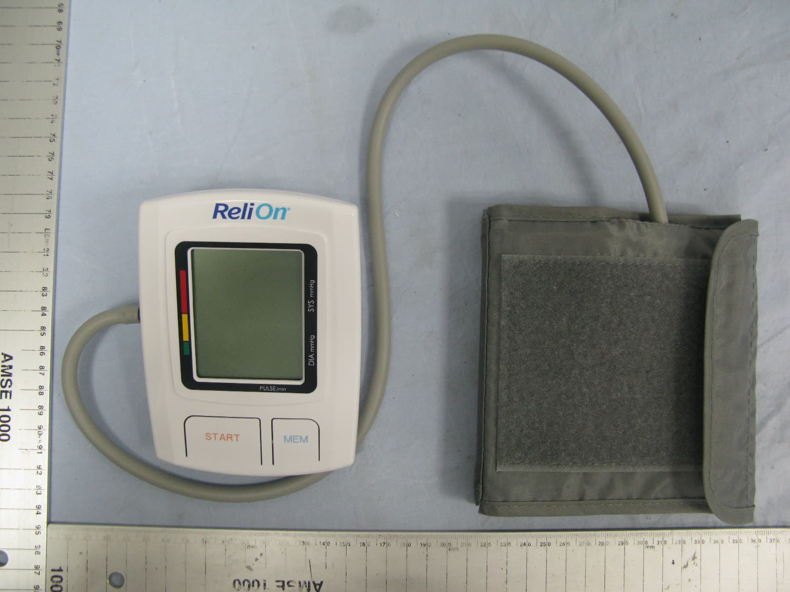
ZRY557BT
Jul 03, 2014Blood Pressure Monitor
Equipment Class
DSS - Part 15 Spread Spectrum Transmitter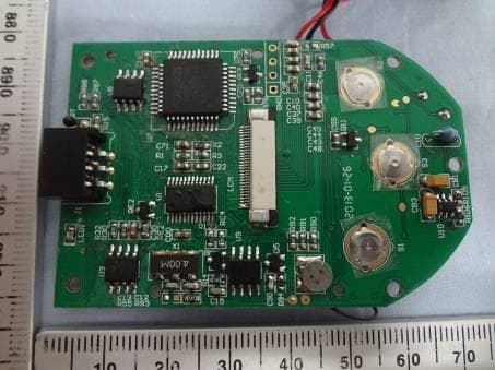
ZRYGMM0001
Jul 11, 2013Blood Glucose Meter
Equipment Class
DSS - Part 15 Spread Spectrum Transmitter
ZRYBG5L
Jun 09, 2013iHealth Wireless Smart Gluco-Monitoring System
Equipment Class
DTS - Digital Transmission System
ZRYPO3
Mar 30, 2013iHealth Pulse Oximeter
Equipment Class
DTS - Digital Transmission System
ZRYAM3
Mar 30, 2013Activity Monitor
Equipment Class
DTS - Digital Transmission System