ZSW-AX535-AX610Mobile Phone
b mobile HK Limited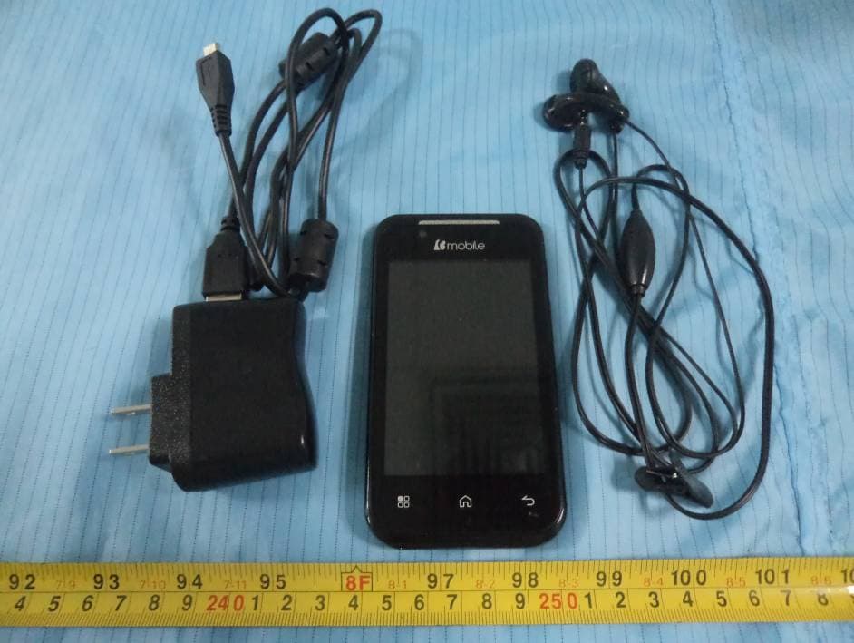
Click to zoom
Application Details
- Equipment Class
- PCE - PCS Licensed Transmitter held to ear
- Date of Grant
- Nov 21, 2013
- Application Purpose
- Original Equipment
- Date of Application
- Nov 21, 2013
- Equipment Note
- Mobile Phone
- Frequency Range
- 1852.40000000 - 1907.60000000
- Company
- b mobile HK Limited
- Country
- China
Documents & Files
Document Text
Text extracted from the exhibit documents filed with the FCC. Open a document above to read the original.
Users Manual
1 Ueser’s Manual AX535 Table of Contents 1.Foreword ............................................................. 2 2.Getting to know your touch phone .................. 5 3.Starting up the device ........................................ 6 4.Introduce the basic phone function ................. 8 5.Technical Specifications ................................. 15 2 1. Foreword Safety In order to ensure the phone is used safely and correctly, please read the precautions below carefully before use. 1.1 General precaution ·Your phone is only suitable for the battery and charger approved by our company or else it may cause the battery to leak, overheat, explode or even catch fire. ·Do not knock, vibrate or throw the phone heavily to avoid malfunction, fire, overheating, explosion or fire. ·If there are abnormal phenomena, like temperature rising, color change or distortion during the usage, charging or storage of the battery, please stop using it and replace it with a new battery. ·It may burn the skin if liquid in the battery leaks onto skin or clothes. If this happens please flush with plenty of clean water immediately and go to a hospital at once. ·Please keep the battery away from fire to avoid fire and explosion if the battery leaks or emits a strange smell. ·Do not place expose the battery to moisture or it may cause overheating, fumes and corrosion. ·Do not use or place the battery under direct sunlight, or in hot places, it may cause leakage and overheating, thus reducing performance and shortening the lifespan. ·Do not charge the battery for over 24 hours continuously. ·Use careful with the earphone maybe possible excessive sound presure from earphones and headphones can cause hearing loss. 1.2 Precaution for the use of charger ·Do not cause short circuit to the charger, or it may cause electric shock, fumes and damage to the charger. ·Do not use the charger if the power wire is broken, or it may cause fire and electric shock. ·Please remove accumulated dust on the power plug. ·Do not put water containers next to the power supply to avoid overheating, fire, electric shock and malfunction in case they come into contact. ·Do not disassemble or tamper with the charger or it may cause personal injury, electric shock, fire and the damage of the charger. ·Do not use the charger in places of high humidity, like 3 bathrooms, or it may cause electric shock, fire and damage of charger. ·Do not touch the charger, power cord or power plug with wet hands or it can cause electric shock. ·Do not put heavy objects on the power cord or change the power cord or it may cause electric shock and fire. ·Please unplug the power socket before cleaning and maintenance. ·Please hold the charger to unplug the socket as pulling the power cord may damage the power wire and cause electric shock and fire. 1.3 Cleaning and maintenance ·As the phone, battery and charger are not waterproof, do not use them in places of high humidity and avoid them being wet by rain. ·Please clean the battery and charger with a soft dry cloth. ·Never use alcohol, thinner or solutions, like benzene, to wipe the phone. ·Dirty sockets can cause poor contact and power down, and even make recharging unavailable. So, please clean them periodically. 1.4 Common Precaution Mobile Phone: ·Please use the phone in an environment with temperature between -20°C- 45°Cand humidity of <75%. ·Please use the phone far away from regular telephones, TV sets, radio sets and office automation equipment, to avoid affecting the normal use of these equipments and mobile phone. Battery: ·Store the battery in cool and ventilated place without direct sunlight. ·The battery has a limited lifespan. The usage of battery will be shortened progressively due to frequent charging. Once the battery is out of use, it means that its lifespan has ended, and you will need to replace it with an approved new battery. ·Do not dispose of old batteries as household waste. Give them to specified disposal places and follow any stipulated instructions for disposal. CAUTION:RISK OF EXPLOSION IF BATTERY IS REPLACED BY AN INCORRECT TYPE.DISPOSE OF USED BATTERIES ACCORDING TO THE INSTRUCYIONS. 4 Charger: ·Do not charge under following conditions: -- places with direct sunlight -- places with ambient temperature less than 0°C or over 40°C, wet or dusty places with strong vibrations (it may cause malfunction) -- places near electrical appliances (it may affect the image and sound) like TV set, radio, etc -- Adapter shall be installed near the equipment and shall be easily accessible.The plug considered as disconnect device of adapter 5 2. Getting to know your touch phone 6 3. Starting up the device To remove the back cover ·Make sure your device is turned off. ·Firmly hold the device with the front panel facing down. ·Slide your finger into the groove at the top of the phone and gently pull open the back cover. To install the SIM card ·Remove the battery if it is installed. ·Locate the SIM card slot, and then insert the SIM card with its gold contacts facing down and its cut-off corner facing out of the card slot as shown in the diagram. ·Slide the SIM card completely into the slot. Note: The phone can support two SIM cards. The card will support 2G card. To install a memory card To have additional storage for your images, videos, music and files, you can purchase a memory card and install it in your device. Locate the memory card slot on the upper part of the exposed right panel. Insert the memory card into the slot with its gold contacts facing down until it clicks into place. 7 To install the battery 1. Align the battery’s exposed copper contacts with the battery connectors at the bottom part of the battery compartment. 2. Insert the contacts side of the battery first and then gently push the battery into place. Replace the back cover. Charging the Battery New batteries are shipped partially charged. Before you start using your device, it is recommended that you install and charge the batt…
Text truncated - open the document above for the full version.
External Photos
EXHIBIT B - EUT EXTERNAL PHOTOGRAPHS EUT – All View EUT – Front View EUT – Rear View EUT – Top View EUT – Bottom View EUT – Left View EUT – Right View EUT – Adapter Label View
ID Label/Location Info
EXHIBIT A - FCC ID LABELING AND LOCATION FCC ID Label FCC ID Label Location The label shown shall be permanently affixed at a conspicuous location on the device and be readily visible to the user at the time purchase (Labeling requirements per 2.925) Label here
Internal Photos
EXHIBIT C - EUT INTERNAL PHOTOGRAPHS EUT – Battery off View EUT – Cover off View 1 GSM&WCDMA Antenna BT&WIFI Antenna EUT – Cover off View 2 EUT – Main Board Top View 1 EUT – Main Board Top View 2 EUT – Main Board Bottom View EUT – Main Board Bottom Shielding off View EUT – LCD Top View EUT – LCD Bottom View EUT – Battery Front View EUT – Battery Rear View
Parts List/Tune Up Info
1 Tune-Up Procedure Tune-Up TX Content 1 Purpose............................................................................................................................. 2 2 General description ..........................................................................................................3 2.1 Characteristics of the transmit burst..................................................................... ......3 2.2 GPRS/Edge Data ransfer................................................................................................3 2.2.1 GSM850&PCS1900 allowed maximum output reduction in a multislot...............3 2.2.2 Edge power description........................................................................4 2.3 UMTS Band2 and Band5 allowed maximum output power Configuration..............4 3 Parameters........................................................................................................................ 4 3.1 Parameters used to shape the burst....................................................................... ......4 3.2 Parameters used to define the temporal position of the burst....................................... 4 3.2.1 Optimum position of the burst................................................................................... 4 3.2.2 Optimum length of the burst...................................................................................... 5 4 Operating mode ................................................................................................................5 4.1 How to transmit a Tch burst (Random data), in GSM850 PCS1900 mode, at power control level max: .............................................................................................................. 5 4.2 How to stop Tx measurements: .................................................................................... 5 4.3 How to transmit a burst after modifying parameters.................................................... 6 5 Purpose............................................................................................................................. 6 6 Automatic frequency control ...........................................................................................6 7 Static frequency error and range.......................................................................................8 2 1 Purpose This panel gives the possibility to manage the mobile in the transmit mode. This window includes both: - All the parameters (frequency band, RF channel, RF level to get the desire antenna output power...) The user needs to make the mobile transmitting, - All the parameters needed to define a transmit burst, - All the compensation table to be able to align the mobile in production. This Tx_commands user guide is describing: - The characteristics of the transmit burst, - All the parameters used in the transmit mode, - The operating mode to make the mobile transmitting 3 2 General description 2.1 Characteristics of the transmit burst for GSM850/PCS The power levels and the shape of a transmit burst are controlled by the power amplifier controller integrated in the MT6572. The burst is generated by a 10-bit DAC from the MT6572 as shown below: The ramping shape is referenced with the rising edge of Tx-ON (from the Baseband). There are two types of parameters define the transmit burst: the first one define the shapes of the burst, and the second one define the temporal position of the burst. The rising and the falling edge of the transmit burst are determined by a set of 32 DAC code values n = 0 ... 31. Tru = TxTRUDefault + △TRU_P + △TRU_T Trd = TxTRD_NBDefault + △TRD_P (for a normal burst). Trd = TxTRD_ABDefault + △TRD_P (for an access burst). 2.2 GPRS Data Transfer for GSM850/PCS 2.2.1 GSM850&PCS1900 allowed maximum output reduction in a multislot GSM mobile phones use a Time Division Multiple Access (TDMA) scheme to transmit data. The TDMA format contains eight time slots. The handset power amplifier typically transmits in four of these up time slots. To prevent interference between cell phones, the time mask profile as specified is very restricted. To meet the 4 GSM time mask, the output power of the PA needs to ramp up and down very quickly while staying within the time mask and not generating extraneous frequency bursts due to too abrupt ramp profiles. As described before, the Vramp input value sets the RF output power. By applying a certain ramp profile to the Vramp pin, the power level (Pout) of the PA is set to obtain the required time mask. A time mask of the PA’s output power is displayed. The time mask meets the limits (displayed by green lines) over a wide range of temperature, voltage and load variations. 2.2.2 Edge power transmit description The direct modulation transmitter(8PSK),combined with a low noise GMSK constant envelope modulator or DFM(Direct-Frequency Modulation),delivers high modulation accuracy with exceptionally low noise and eliminates the need for tansmit SAW filters in any of the supported GGE bands. The max Edge power for GSM850 is tipically 26.5dBm with the range 26-27.6dBm for MTK; The max Edge power for PCS is tipically 25.5dBm with the range 24-27.0dBm for MTK; 2.3 UMTS Band2 and Band5 transmit max power Max power range for both band2 and band5 listed as below: Max Target Power for Production Unit (dBm) Mode/Band Channel Low Middle High WCDMA850 22.50 22.50 22.50 WCDMA1900 22.50 22.50 22.50 Transmitter consists of 5 output ports.TX_LB2 and TX_HB1 ports are multi-mode ports which can support 2G or 3G depending on application circuits on the phone.Typ. 5 maximum TX output power is>0dBm.Overall TX gain dynamic range is 78dB in RF and 8dB in BB.The power detections circuits are also included for better power accuracy over power region of PA gain mode change.In order to ensure power detection accuracy,the PCB trace to DET pin should not be put too close to TX output singal traces. 3 Parameters F (n) are values coming fro…
Text truncated - open the document above for the full version.
RF Exposure Info
Note: This test report is prepared for the customer shown above and for the equipment described herein. It may not be duplicated or used in part without prior written consent from Bay Area Compliance Laboratories Corp. SAR EVALUATION REPORT For b mobile HK Limited G/F. 144 UN CHAU STREET, SHAM SHUI PO, KOWLOON, HONGKONG FCC ID: ZSW-AX535-AX610 Report Type: Original Report Product Type: Mobile Phone Test Engineer: Sandy Wang Report Number: RSZ131008003-20 Report Date: 2013-11-18 Reviewed By: Alvin Huang RF Leader Prepared By: Bay Area Compliance Laboratories Corp. (Shenzhen) 6/F, the 3rd Phase of WanLi Industrial Building, ShiHua Road, FuTian Free Trade Zone Shenzhen, Guangdong, China Tel: +86-755-33320018 Fax: +86-755-33320008 www.baclcorp.com.cn Bay Area Compliance Laboratories Corp. (Shenzhen) Report No: RSZ131008003-20 SAR Evaluation Report 2 of 140 Attestation of Test Results EUT Information Company Name b mobile HK Limited EUT Description Mobile Phone FCC ID ZSW-AX535-AX610 Model Number AX535 Test Date 2013-11-14 to 2013-11-16 Frequency Max. SAR Level(s) Reported Limit(W/Kg) GSM 850 0.270 W/kg 1g Head SAR 1.366 W/kg 1g Body SAR 1. 6 PCS 1900 0.956 W/kg 1g Head SAR 0.901 W/kg 1g Body SAR WCDMA850 0.333 W/kg 1g Head SAR 0.449 W/kg 1g Body SAR WCDMA1900 0.197 W/kg 1g Head SAR 0.310 W/kg 1g Body SAR Simultaneous 1.328 W/kg 1g Head SAR 1.522 W/kg 1g Body SAR Applicable Standards ANSI / IEEE C95.1 : 2005 IEEE Standard for Safety Levels with Respect to Human Exposure to Radio Frequency Electromagnetic Fileds,3 kHz to 300 GHz. ANSI / IEEE C95.3 : 2002 IEEE Recommended Practice for Measurements and Computations of Radio Frequency Electromagnetic Fields With Respect to Human Exposure to SuchFields,100 kHz—300 GHz. IEEE1528:2003 IEEE Recommended Practice for Determining the Peak Spatial-Average Specific Absorption Rate (SAR) in the Human Head from Wireless Communications Devices: Measurement Techniques KDB procedures KDB 447498 D01 Mobile and Portable Devices RF Exposure Procedures and Equipment Authorization Policies. KDB 648474 D04 SAR Evaluation Considerations for Wireless Handsets KDB 865664 D01 SAR Measurement Requirements for 100 MHz to 6 GHz KDB 941225 D01 SAR Measurement Procedures for 3G Devices-CDMA 2000/EV-Do WCDMA/HSDPA/HSUPA KDB 941225 D06 SAR Evaluation Procedures for Portable Devices with Wireless Router Capabilities. Note: This wireless device has been shown to be capable of compliance for localized specific absorption rate (SAR) for General Population/Uncontrolled Exposure limits specified in ANSI/IEEE Standards and has been tested in accordance with the measurement procedures specified in IEEE 1528-2003 and RF exposure KDB procedures. The results and statements contained in this report pertain only to the device(s) evaluated. Bay Area Compliance Laboratories Corp. (Shenzhen) Report No: RSZ131008003-20 SAR Evaluation Report 3 of 140 TABLE OF CONTENTS DOCUMENT REVISION HISTORY ......................................................................................................................... 5 EUT DESCRIPTION .................................................................................................................................................... 6 TECHNICAL SPECIFICATION ......................................................................................................................................... 6 REFERENCE, STANDARDS, AND GUILDELINES ............................................................................................... 7 SAR LIMITS ................................................................................................................................................................. 8 FACILITIES .................................................................................................................................................................. 9 DESCRIPTION OF TEST SYSTEM ........................................................................................................................ 10 EQUIPMENT LIST AND CALIBRATION ............................................................................................................. 17 EQUIPMENTS LIST & CALIBRATION INFORMATION .................................................................................................... 17 SAR MEASUREMENT SYSTEM VERIFICATION .............................................................................................. 18 LIQUID VERIFICATION ............................................................................................................................................... 18 SYSTEM ACCURACY VERIFICATION ........................................................................................................................... 21 SAR SYSTEM VALIDATION DATA ..................................................................................................................... 22 EUT TEST STRATEGY AND METHODOLOGY ................................................................................................. 30 TEST POSITIONS FOR DEVICE OPERATING NEXT TO A PERSON’S EAR........................................................................ 30 CHEEK/TOUCH POSITION ........................................................................................................................................... 31 EAR/TILT POSITION ................................................................................................................................................... 31 TEST POSITIONS FOR BODY-WORN AND OTHER CONFIGURATIONS .............................................................................. 32 SAR EVALUATION PROCEDURE ................................................................................................................................. 33 CONDUCTED OUTPUT POWER MEASUREMENT ........................................................................................... 34 PROVISION APPLICABLE .........................…
Text truncated - open the document above for the full version.
Test Report
Note: This test report is prepared for the customer shown above and for the device described herein. It may not be duplicated or used in part without prior written consent from Bay Area Compliance Laboratories Corp. FCC PART 22H, PART 24E TEST REPORT For b mobile HK Limited G/F. 144 UN CHAU STREET, SHAM SHUI PO, KOWLOON, HONGKONG FCC ID: ZSW-AX535-AX610 Report Type: Original Report Product Type: Mobile Phone Test En gineer: Rocky Kang Re port Number: RSZ131008003-00D Re port Date: 2013-11-22 Reviewed B y: Alvin Huang RF Leade r Prepared By: Bay Area Compliance Laboratories Corp. (Shenzhen) 6/F, the 3rd Phase of WanLi Industrial Building ShiHua Road, FuTian Free Trade Zone Shenzhen, Guangdong, China Tel: +86-755-33320018 Fax: +86-755-33320008 www.baclcorp.com.cn Bay Area Compliance Laboratories Corp. (Shenzhen) Report No.: RSZ131008003-00D FCC Part 22H/24E Page 2 of 42 TABLE OF CONTENTS GENERAL INFORMATION ....................................................................................................................................... 3 PRODUCT DESCRIPTION FOR EQUIPMENT UNDER TEST (EUT) ..................................................................................... 3 OBJECTIVE ................................................................................................................................................................... 3 RELATED SUBMITTAL(S)/GRANT(S) ............................................................................................................................. 3 TEST METHODOLOGY .................................................................................................................................................. 3 TEST FACILITY ............................................................................................................................................................. 4 SYSTEM TEST CONFIGURATION .......................................................................................................................... 5 DESCRIPTION OF TEST CONFIGURATION ...................................................................................................................... 5 EQUIPMENT MODIFICATIONS ....................................................................................................................................... 5 BLOCK DIAGRAM OF TEST SETUP ................................................................................................................................ 5 SUMMARY OF TEST RESULTS ............................................................................................................................... 6 FCC §1.1307 & §2.1093 - RF EXPOSURE .................................................................................................................. 7 APPLICABLE STANDARD .............................................................................................................................................. 7 TEST RESULT ............................................................................................................................................................... 7 FCC §2.1047 - MODULATION CHARACTERISTIC .............................................................................................. 8 FCC § 2.1046, § 22.913 (A) & § 24.232 (C) - RF OUTPUT POWER ........................................................................ 9 APPLICABLE STANDARD .............................................................................................................................................. 9 TEST PROCEDURE ........................................................................................................................................................ 9 TEST EQUIPMENT LIST AND DETAILS ........................................................................................................................... 9 TEST DATA ................................................................................................................................................................ 10 FCC §2.1049, §22.917, §22.905 & §24.238 - BANDWIDTH .................................................................................... 14 APPLICABLE STANDARD ............................................................................................................................................ 14 TEST PROCEDURE ...................................................................................................................................................... 14 TEST EQUIPMENT LIST AND DETAILS ......................................................................................................................... 14 TEST DATA ................................................................................................................................................................ 14 FCC §2.1051, §22.917(A) & §24.238(A) - SPURIOUS EMISSIONS AT ANTENNA TERMINALS .................. 23 APPLICABLE STANDARD ............................................................................................................................................ 23 TEST PROCEDURE ...................................................................................................................................................... 23 TEST EQUIPMENT LIST AND DETAILS ......................................................................................................................... 23 TEST DATA ................................................................................................................................................................ 23 FCC §2.1053, §22.917 & §24.238 - SPURIOUS RADIATED EMISSIONS ........................................................... 29 APPLICABLE STANDARD ............................................................................................................................................ 29 TEST PROCEDURE ..............................................…
Text truncated - open the document above for the full version.
Test Setup Photos
EXHIBIT D - TEST SETUP PHOTOGRAPHS Radiated Emissions Test View (Below 1 GHz) Radiated Emissions Test View (Above 1 GHz) Extreme Condition View
Contact Information
Applicant
Carlos Lopez
Test Firm
Bay Area Compliance Laboratory Corp. (Shenzhen)John Chan
Technical Specifications
| # | Rule Parts | Frequency Range | Power Output | Emission | Tolerance |
|---|---|---|---|---|---|
| 6 | 24E | 1.85 GHz - 1.91 GHz | 136.00 mW | 4M19F9W | 2.5 ppm |
Other Applications from b mobile HK Limited
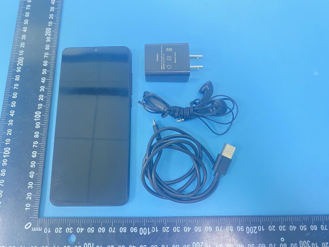
ZSW-30-144
Apr 16, 2026Mobile Phone
Equipment Class
PCE - PCS Licensed Transmitter held to ear
ZSW-10-052
Jan 21, 2026Mobile Phone
Equipment Class
PCE - PCS Licensed Transmitter held to ear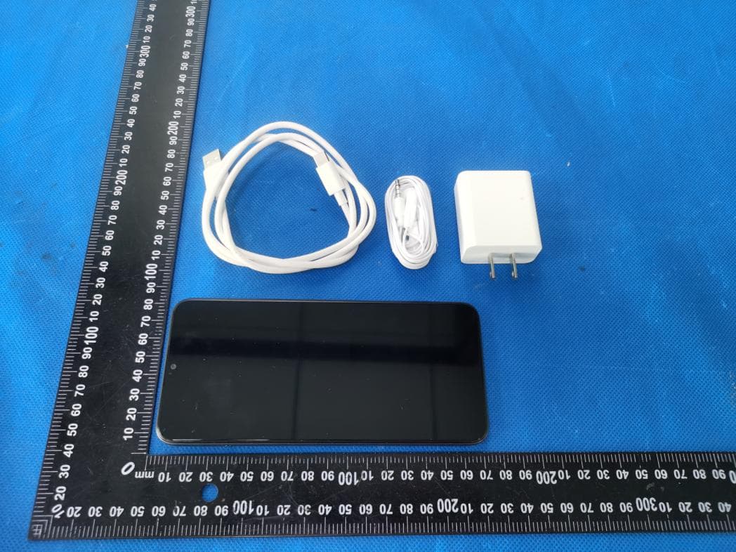
ZSW-30-143
Nov 20, 2025Mobile Phone
Equipment Class
JBP - Part 15 Class B Computing Device Peripheral
ZSW-30-136
Jan 24, 2025Mobile Phone
Equipment Class
PCE - PCS Licensed Transmitter held to ear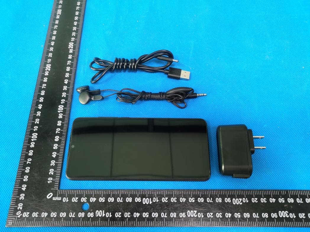
ZSW-30-135
Sep 10, 2024Mobile Phone
Equipment Class
DSS - Part 15 Spread Spectrum Transmitter