ZT9-TZ207021V2915 MHz USB Dongle
Toumaz Microsystems Ltd.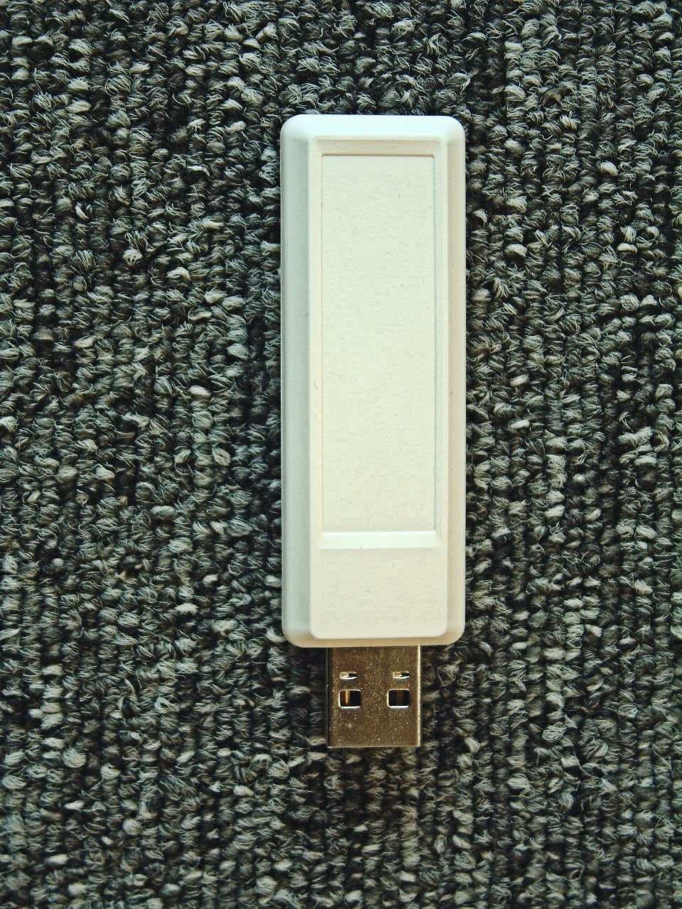
Click to zoom
Application Details
- Equipment Class
- DXT - Part 15 Low Power Transceiver, Rx Verified
- Date of Grant
- Oct 23, 2011
- Application Purpose
- Original Equipment
- Date of Application
- Oct 23, 2011
- Equipment Note
- 915 MHz USB Dongle
- Frequency Range
- 903.20000000 - 927.80000000
- Company
- Toumaz Microsystems Ltd.
- Country
- United Kingdom
Documents & Files
Document Text
Text extracted from the exhibit documents filed with the FCC. Open a document above to read the original.
Users Manual
connected freedom Toumaz UK Limited Building 3, 115 Milton Park, Abingdon, OX14 4RZ, UK Tel: +44 1235 438 950 Email: info@ www.toumaz.com Web: www.toumaz.com Toumaz Asia 11F No. 285, Sec 2, Tiding Blvd. Neihu District, Taipei Tel: +886 2 2799 8108 Telran TDK Kit User Guide Telran TDK TZ2070-IFU_v2.02 Sep 2011 connected freedom TZ2070-IFU ver 2.02 Sep 2011 Page 2 of 58 Copyright 2011 Toumaz UK Limited This document contains and refers to proprietary information, which is protected by copyright. Reproduction of any part of this document is prohibited without the prior written permission of Toumaz UK Limited. Notices Information contained in this publication regarding the Telran TZ1053 and the Telran TDK is provide as-is and may be superseded by updates. It is the Users responsibility to see that his/hers applications meets their own specifications. TOUMAZ MAKES NO REPRESENTATIONS OR WARRANTIES OF ANY KIND WHETHER EXPRESS OR IMPLIED, WRITTEN OR ORAL, STATUTORY OR OTHERWISE, RELATED TO THE INFORMATION, INCLUDING BUT NOT LIMITED TO ITS CONDITION, QUALITY, PERFORMANCE, MERCHANTABILITY OR FITNESS FOR PURPOSE. Toumaz disclaims all liability arising from this information and its use. Use of Toumaz’s products as critical components in life support systems is not authorized except with express written approval by Toumaz. No licenses are conveyed, implicitly or otherwise, under any Toumaz intellectual property rights. All information in this document is subject to change without notice. The products supplied may differ in appearance from that shown. Trademarks The Toumaz™ name and logo, and Telran™ are registered trademarks of Toumaz UK Limited. The Microchip name and logo, KEELOQ, MPLAB, PIC, are the registered trademarks of Microchip Technology Incorporated. UMI and the UMI logo are trademarks of Cambridge Consultants Ltd. All other trademarks mentioned herein are the property of their respective companies Document Revision History Issue Description Author Date 1.00 First Version for Telran TDK AM 20-Jan-2011 2.00 Updated for Version 2 TDKs AM 06-Jul-2011 2.01 Updated for Version 2 TDKs AM 10-Aug-2011 2.02 Safety Information Updated AM 22-Sep-2011 connected freedom TZ2070-IFU ver 2.02 Sep 2011 Page 3 of 58 Contents Copyright 2011 Toumaz UK Limited ............................................................................... 2 Notices ................................................................................................................................ 2 Trademarks ......................................................................................................................... 2 Document Revision History ................................................................................................ 2 Contents ............................................................................................................................. 3 Figures ................................................................................................................................ 5 1. Introduction ......................................................................................................................... 6 1.1 Document Layout................................................................................................................ 6 1.2 Screen Displays .................................................................................................................. 7 1.3 Conventions Used in this Guide ......................................................................................... 7 1.4 Recommended Reading ..................................................................................................... 7 1.5 The Toumaz Web Site ........................................................................................................ 7 1.6 Abbreviations ...................................................................................................................... 8 1.7 Customer Support............................................................................................................... 8 2. Regulatory Approval ........................................................................................................... 9 2.1 USA .................................................................................................................................... 9 2.2 Canada ............................................................................................................................. 10 2.2.1 Radio Frequency Module ................................................................................................. 10 2.2.2 USB Dongle ...................................................................................................................... 10 2.2.3 Sensor Development Board ............................................................................................. 10 2.3 Europe .............................................................................................................................. 11 2.3.1 Helpful Web Sites: ............................................................................................................ 12 3. Telran TDK Kit Contents ................................................................................................... 13 3.1 Deliverables ...................................................................................................................... 13 3.2 Electrostatic Warning ........................................................................................................ 14 3.3 Safety Notice .................................................................................................................... 14 3.4 Waste Electrical and Electronic Equipment (WEEE)........................................................ 14 3.5 Telran TDK Hardware Features ....................................................................................... 15 3.5.1 Telran TDK R…
Text truncated - open the document above for the full version.
Internal Photos
FCC ID: ZT9-TZ207021V2 IC ID:9809A-TZ207021V2 Toumaz UK Ltd TZ207021 – Telran USB Dongle 2011 Not to be reproduced, except in its entirety, Page 1 of 1 without the Permission of TÜV SÜD Product Service Ltd Reference: 75914477 PHOTOGRAPHS OF EQUIPMENT USB Dongle – Cover Removed PCB - Bottom View PCB - Top View
Operational Description
connected freedom TELRAN Technical Description Page 1 of 10 This copy printed on 9-Sep-11 1 Introduction This document specifies the tests and assessments that are required on the Telran TDK and it’s component parts that will allow regulatory approval in Canada, US and EU. This will allow:- Regulatory bodies to assess if the test and assessment regime as satisfactory to allow regulatory approval before testing. 3rd Part test laboratories to provide competitive costs for the testing involved. Toumaz to provide sufficient number and quality of test samples for the testing. 2 Product Overview The products that require approval are:- A USB Dongle. A Radio Transceiver Module. A Sensor Development Board. A TDK (consisting of the USB Dongle and both boards). The TDK is intended for use within an electronic engineering R&D environment. Usual laboratory ESD precautions are expected. connected freedom TELRAN Technical Description Page 2 of 10 This copy printed on 9-Sep-11 The RF Module is designed to be used and sold as a component of customer designed larger systems to provide low power wireless communications. It is not intended to be used as stand-alone equipment. The Sensor Development Board is designed as a development aid for engineers. It is expected to be used and sold solely for this reason and not as stand-alone equipment. The USB Dongle is designed for use with other Toumaz systems as well as the Telran TDK. There are 2 versions of these products, one for the North American market and one for the European Market. Description Europe North America TDK consisting of:- TZ1053TDK868 (Marketing) TZ1053TDK915 (Marketing) USB Dongle TZ207020-ASY TZ207021-ASY RF Module TZ1053RFM868 (Marketing) TZ207010-PCBA (Engineering) TZ1053RFM915 (Marketing) TZ207011-PCBA (Engineering) Sensor Development Board TZ207030-PCBA connected freedom TELRAN Technical Description Page 3 of 10 This copy printed on 9-Sep-11 3 Product Description 3.1 USB Dongle – TZ20702x The USB Dongle consists of a PIC micro processor, a RF transceiver, a FTDI USB transceiver and SPI RAM on a single PCB housed in a New Age Enclosure, P1A-260906U housing. This is shown in Figure 1. Figure 1 USB Dongle Functional Block Diagram 3.1.1 Digital A PIC 18LF25K22 microcontroller acts as a local host controller. It has an ISP connector to allow the PIC to be programmed. The PIC uses its internal 16 MHz oscillator. Two PIC USART connections are used to allow either the Telran, TZ1053 to communications directly with a PC via a USB interface, or the Telran to communicate via the PIC with a PC. NC7SZ157 gates are used to switch the data paths. A 256K SPI Bus Low-Power Serial SRAM (23A256) is used to allow greater storage and manipulation of data. The USB interface uses a FTDI FT232RQ. The USB port is protected by a TPD4E001 ESD diode array. LEDs show the states of the Telran status pins. These are for R&D use only and are not visible to the end user. 3.1.2 Radio The radio circuit is the same as the RF Module described in § 0. However the PCB layout is different. 3.1.3 Power Power is derived from the USB bus and regulated down to 3.3V by the FTDI IC for the PIC and further to 1.25 V by a MAX8863 LDO. PIC SPI Memory 5 x LEDs Serial Routing Circuitry USB Serial Data Telran TZ1053 Antenna Matching SPI Bus & Control USB Interface IC USB Connector, J3 PIC Reset, SW2 PIC Programming Port, J5 connected freedom TELRAN Technical Description Page 4 of 10 This copy printed on 9-Sep-11 3.1.4 USB Dongle information Item Value Comments Power supply sources USB 5.0 V nominal (4.4 V to 5.25 V.) Dimensions 65 x 23 x 15 mm (w x h x d) including USB Connector Temperature Range 0 to + 70 °C Connection Ports USB A connected freedom TELRAN Technical Description Page 5 of 10 This copy printed on 9-Sep-11 3.2 Radio Transceiver Module – TZ20701x The RTM consists of a single bare PCB with a Telran RF transceiver IC and integrated antenna. The North American version is houses the active RF circuits under a screening can. The unit is powered by a LR44 Alkaline cell, but an external power source can be used on the EU version. 3.2.1 RF Module Summary Item Value Comments Power supply sources Alkaline Cell LR44 nominal 1.5 V Operational Supply Range 1.08 to 1.50V Dimensions 43 x 23 x 7 mm (w x h x d) without battery holder. 43 x 23 x 14 mm (w x h x d) with battery holder. Temperature Range 0 to + 70 °C Connection Ports Digital Interface 20 Way 2 x 10 0.05” Samtec RF Test U-FL Hirose 3.2.2 Operational Frequencies The transceiver is designed to operate in the 866 MHz SRD band in Europe and the 915 MHz ISM band in the USA. Details of the frequency ranges are in Table 1. Table 1 Frequency Bands Frequency Bands From To Europe 863 870.0 US 902 928 3.2.3 Transceiver Description The radio is operates in a TDMA (Time Division Multiple Access) system using the same uplink and downlink frequency. The full RF system is contained in the Toumaz Telran TZ1053 IC along with a few additional components. The transceiver system consists of a separate Single Super-heterodyne transmit and receive chains with a common Local Oscillator System. The channel spacing is 200 kHz. This is shown in Figure 2 and described in greater detail in the following sections. 3.2.4 Transmitter The transmit section of the Telran transceiver comprises I Q modulation from baseband up to an IF of approximately 100 MHz followed by a final up conversion by 800 MHz to a final transmit frequency of around 900 MHz. The PA stage is designed to deliver up to -3dBm into a matched antenna load. The PA output stage is open drain and requires an external inductor as a load and a series capacitor match to a 50ohm SAW filter. The transceiver uses an on-chip switch to connect to a common SAW filter and antenna path. The PA circuitry incorporates a control loop which holds connected freedom TELRAN Technical Description Page 6 of 10 This copy printed on 9-Sep-11 the output power at the correct level. Control of the PA output power is in appr…
Text truncated - open the document above for the full version.
Test Report
Document 75914477 Report 03 Issue 2 October 2011 Report On Limited FCC and Industry Canada Testing of the Toumaz UK Ltd Telran TDK In accordance with FCC CFR 47 Part 15C and Industry Canada RSS-210 COMMERCIAL-IN-CONFIDENCE FCC IDs: RF Module: ZT9-TZ207011V2 , USB Dongle: ZT9-TZ207021V2 IC IDs: RF Module: 9809A-TZ207011V2 , USB Dongle: 9809A-TZ207021V2 TÜV SÜD Product Service Ltd, Octagon House, Concorde Way, Segensworth North, Fareham, Hampshire, United Kingdom, PO15 5RL Tel: +44 (0) 1489 558100. Website: www.tuvps.co.uk COMMERCIAL-IN-CONFIDENCE Document 75914477 Report 03 Issue 2 Page 1 of 48 COMMERCIAL-IN-CONFIDENCE REPORT ON Limited FCC and Industry Canada Testing of the Toumaz UK Ltd Telran TDK In accordance with FCC CFR 47 Part 15C and Industry Canada RSS-210 Document 75914477 Report 03 Issue 2 October 2011 PREPARED FOR Toumaz UK Ltd Building 3 115 Milton Park Abingdon Oxfordshire OX14 4RZ PREPARED BY Natalie Bennett Senior Administrator APPROVED BY Mark Jenkins Authorised Signatory DATED 14 October 2011 This report has been up issued to Issue 2 to include additional testing. ENGINEERING STATEMENT The measurements shown in this report were made in accordance with the procedures described on test pages. All reported testing was carried out on a sample equipment to demonstrate limited compliance with FCC CFR 47 Part 15C and Industry Canada RSS-210. The sample tested was found to comply with the requirements defined in the applied rules. Test Engineer(s); R Henley G Lawler B Airs Document 75914477 Report 03 Issue 2 Page 2 of 48 COMMERCIAL-IN-CONFIDENCE COMMERCIAL-IN-CONFIDENCE CONTENTS Section Page No 1 REPORT SUMMARY ................................................................................................................... 3 1.1 Introduction ................................................................................................................................... 4 1.2 Brief Summary of Results ............................................................................................................. 5 1.3 Application Form ........................................................................................................................... 6 1.4 Product Information ...................................................................................................................... 8 1.5 Test Conditions ............................................................................................................................. 8 1.6 Deviations from the Standard ....................................................................................................... 8 1.7 Modification Record ...................................................................................................................... 8 2 TEST DETAILS ............................................................................................................................ 9 2.1 AC Line Conducted Emissions ................................................................................................... 10 2.2 Field Strength of Fundamental ................................................................................................... 13 2.3 Field Strength of Spurious Emissions ......................................................................................... 20 2.4 Occupied Bandwidth Testing ...................................................................................................... 39 3 TEST EQUIPMENT USED ......................................................................................................... 44 3.1 Test Equipment Used ................................................................................................................. 45 3.2 Measurement Uncertainty .......................................................................................................... 46 4 ACCREDITATION, DISCLAIMERS AND COPYRIGHT ............................................................ 47 4.1 Accreditation, Disclaimers and Copyright ................................................................................... 48 Document 75914477 Report 03 Issue 2 Page 3 of 48 COMMERCIAL-IN-CONFIDENCE COMMERCIAL-IN-CONFIDENCE SECTION 1 REPORT SUMMARY Limited FCC and Industry Canada Testing of the Toumaz UK Ltd Telran TDK In accordance with FCC CFR 47 Part 15C and Industry Canada RSS-210 Document 75914477 Report 03 Issue 2 Page 4 of 48 COMMERCIAL-IN-CONFIDENCE COMMERCIAL-IN-CONFIDENCE 1.1 INTRODUCTION The information contained in this report is intended to show verification of the Limited FCC and Industry Canada Testing of the Toumaz UK Ltd Telran TDK to the requirements of FCC CFR 47 Part 15C and Industry Canada RSS-210. Objective To perform Limited FCC and Industry Canada Testing to determine the Equipment Under Test's (EUT’s) compliance with the Test Specification, for the series of tests carried out. Manufacturer Toumaz UK Ltd Model Number(s) Telran RF Module: TZ207011 Telran USB Dongle: TZ207021 Serial Number(s) DD 21 30 14 84 915 DD 21 90 A4 B4 915 Number of Samples Tested 2 Test Specification/Issue/Date FCC CFR 47 Part 15C: 2010 Industry Canada RSS-210: 2010 Incoming Release Date Application Form 17 July 2011 Disposal Reference Number Date Held Pending Disposal Not Applicable Not Applicable Order Number Date 4408 24 June 2011 Start of Test 31 July 2011 Finish of Test 12 October 2011 Name of Engineer(s) R Henley G Lawler B Airs Related Document(s) ANSI C63.10: 2009 Document 75914477 Report 03 Issue 2 Page 5 of 48 COMMERCIAL-IN-CONFIDENCE COMMERCIAL-IN-CONFIDENCE 1.2 BRIEF SUMMARY OF RESULTS A brief summary of the tests carried out in accordance with FCC CFR 47 Part 15C and Industry Canada RSS-210 is shown below. Section Spec Clause Test Description Result Comments/Base Standard USB Dongle 2.1 15.207 AC Line Conducted Emissions Pass 2.2 15.249 (a) and A2.9 Field Strength of Fundamental Pass 2.3 15.249 (a)(d), 15.209 and A2.9 Field Strength of Spurious Emissions Pass 2.4 AN…
Text truncated - open the document above for the full version.
Test Setup Photos
FCC ID: ZT9-TZ207021V2 IC ID:9809A-TZ207021V2 Toumaz UK Ltd TZ207021 – Telran USB Dongle 2011 Not to be reproduced, except in its entirety, Page 1 of 1 without the Permission of TÜV SÜD Product Service Ltd Reference: 75914477 PHOTOGRAPHS OF TEST SET UP 30MHz-1GHz – Radiated Emissions 1GHz-10GHz – Radiated Emissions
Contact Information
Applicant
Simon Pearmain(Mr)
Test Firm
TUV SUD Product ServiceMark Jenkins
Technical Specifications
| # | Rule Parts | Frequency Range | Power Output |
|---|---|---|---|
| 1 | 15C | 903.2 MHz - 927.8 MHz | - |
Other Applications from Toumaz Microsystems Ltd.
ZT9-TZ207011V2
Oct 05, 2011915 MHz RF Module
Equipment Class
DXT - Part 15 Low Power Transceiver, Rx Verified