ZTUDCT1905DECT Phone
CETIS,INC.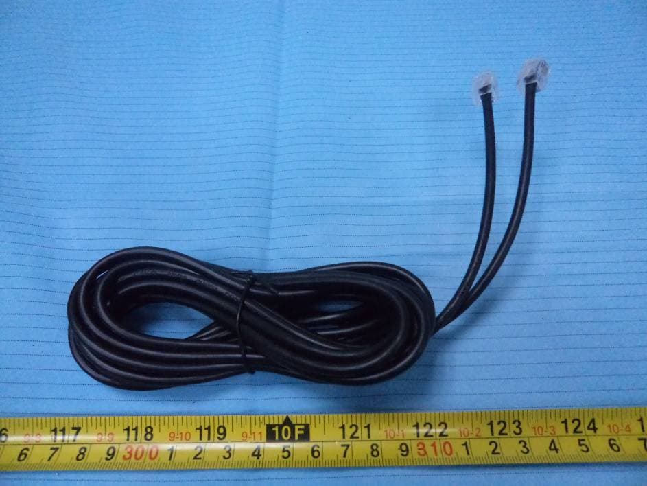
Click to zoom
Application Details
- Equipment Class
- PUB - Part 15 Unlicensed PCS Base Station
- Date of Grant
- Aug 03, 2012
- Application Purpose
- Original Equipment
- Date of Application
- Aug 03, 2012
- Equipment Note
- DECT Phone
- Frequency Range
- 1921.53600000 - 1928.44800000
- Company
- CETIS,INC.
- Country
- United States
Documents & Files
Document Text
Text extracted from the exhibit documents filed with the FCC. Open a document above to read the original.
Users Manual
INCLUDED IN YOUR PACKAGE Cordless HandsetAC Adapter Base UnitUser Guide Battery PackRJ-11 Line Cord Rubber Battery Screw CoverRJ-45 Cable Phillips ScrewClear Plastic Overlay PREPARING TO USE THE DCT1900 SERIES 1. Prepare to install the battery into the cordless handset by firmly pressing down on the top of the battery cover and sliding it off. If cover is secured with a screw, remove the screw first. 2. Locate the lightly embossed numbers “1” and “2” on the battery’s plastic connector. 3. Insert the battery connector into the handset’s connector with the embossed numbers facing up. Note: The handset may “beep” when the battery is connected. This is not an indication that the telephone is ready to use. To obtain optimal perform- ance of the telephone, be sure to charge the battery for 15 to 20 hours. 4. Replace the battery compartment cover and retaining screw. 5. Insert the provided rubber screw cover. 6. Turn the telephone base so the back panel is facing you. Insert either end of the RJ-45 cable into the jack on the back of the telephone labeled LINE. 7. Insert the other end of the cable into the jack on the AC adapter labeled PHONE. 8. Insert one end of the RJ-11 line cord into the jack on the AC adapter labeled LINE. 9. Insert the other end of this line cord into a telephone jack. 10. Plug the AC adapter into an unswitched electrical outlet. 11. Once your telephone is connected, remove the plastic overlay and place the paper faceplate over the keys. Replace the plastic overlay by hooking the tabs on the overlay into the recessed slots located on both sides. The overlay is easiest to insert when the left or right side tabs are inserted first, and the middle of the overlay is slightly bowed to allow for insertion of the other tabs. 12. Place the cordless handset on the base unit. CHARGING THE BATTERY The rechargeable battery must be fully charged before using the phone for the first time. It is recommended that that battery pack be charged for approximately 15 to 20 hours, without interruption, before use. To charge the battery, place the handset, keypad down, in the base unit. Make sure the CHARGELED on the base lights. If the LED does not light: 1. Ensure that the AC adapter is plugged in. 2. Ensure that the AC adapter is not plugged into a switched electrical outlet. 3. Ensure that the handset charging contacts at the bottom of the handset are making good contact with the base unit’s charging contacts. CLEANING THE BATTERY CONTACTS To maintain a good charge, it is important to clean all charging contacts on the handset and base unit. Use a pencil eraser or other contact cleaner. Do not use any liquids or solvents. BATTERY SAFETY INSTRUCTIONS 1. Use only Teledex-approved battery replacements. 2. Dispose of used batteries according to local codes pertaining to rechargeable batteries. 3. Do not dispose of batteries in fire, as they may explode 4. Charge the telephone's batteries only while in the telephone handset, and only by using the telephone base unit to charge. Do not attempt to remove the batteries and charge them in a separate charging unit. 5. Do not short-circuit the battery pack, as this may cause it to explode or catch fire. HANDSET/BASE REGISTRATION PROCEDURE This procedure establishes an exclusive link between a specific handset and base, thereby allowing no other access to this specific base. To accomplish this procedure, place the handset on the base in the charging position. The LINE indicator will blink while the process is occuring. This process occurs each time the handset is placed on the base in the charging cradle. ADJUSTING THE RING VOLUME The up and down volume keys will adjust the ringer volume of the telephone. Additionally, the DCT1900 series telephone has an optional “courtesy” ring mode, wherein the ring volume begins at the lowest setting, then automatically rings louder with each successive ring during an incoming call. To select the courtesy ring mode, follow these steps: Press the FLASHkey; then the 4key; then the STOREkey; then the 1key. To return to regular ring mode: Press the FLASHkey; then the 1 key; then the STOREkey; then the 1key. ADJUSTING SPEAKERPHONE VOLUME The speakerphone has eight (8) levels. To adjust speakerphone volume, locate the volume up/down keys, located on the front surface of the phone below the keypad. With the speaker active, press the “down” arrow key to decrease the volume level, and press the “up” arrow key to increase it. - IF THE PRODUCT HAS BEEN DROPPED OR THE CABINET HAS BEEN DAM- AGED. - IF THE PRODUCT EXHIBIT A DISTINCT CHANGE IN PERFORMANCE. 10. AVOID USING A TELEPHONE (OTHER THAN A CORDLESS TYPE) DURING AN ELECTRICAL STORM. THERE MAY BE A REMOTE RISK OF ELECTRIC SHOCK FROM LIGHTNING. 11. DO NOT USE THE TELEPHONE TO REPORT A GAS LEAK IN THE VICINITY OF THE LEAK. PLEASE SAVE THESE INSTRUCTIONS DCT1900 SERIES DIAGRAM DCT1900 SERIES USERS GUIDE 1.9 GHz DECT Single-Line Digital Cordless Telephone Part Number 600-0480-77 Copyright © 2006 Teledex LLC. ALL RIGHTS RESERVED. Telephone (408) 363-3100 (800) 794-8353 Internet www.teledex.com store.teledex.com Email [email protected] Mailing Address 6311 San Ignacio Avenue San Jose, CA 95119 USA CONTACTING TELEDEX 8. TO REDUCE THE RISK OF ELECTRIC SHOCK DO NOT DISASSEMBLE THIS PRODUCT. BUT TAKE IT TO A QUALIFIED SERVICE FACILITY IF SERVICE OR REPAIR WORK IS REQUIRED. OPENING OR REMOVING COVERS MAY EXPOSE YOU TO DANGEROUS VOLTAGES OR OTHER RISKS. INCORRECT REASSEMBLY CAN CAUSE ELECTRIC SHOCK WHEN THE APPLIANCE IS SUBSE- QUENTLY USED. 9. UNPLUG THIS PRODUCT FROM THE WALL OUTLET AND REFER SERVICING TO QUALIFIED SERVICE PERSONNEL UNDER THE FOLLOWING CON- DITIONS: - WHEN THE POWER SUPPLY CORD OR PLUG IS DAMAGED OR FRAYED. - IF LIQUID HAS BEEN SPILLED INTO THE PRODUCT. - IF THE PRODUCT HAS BEEN EXPOSED TO RAIN OR WATER. - IF THE PRODUCT DOES NOT OPERATE NORMALLY BY FOLLOWING THE OPERATING INSTRUCTIONS. ADJUST ONLY THOSE CONTROLS THAT ARE COV- ERED BY THE OPERATING INSTRUCTIONS, AS IMPR…
Text truncated - open the document above for the full version.
Cover Letter(s)
Cetis, Inc. 5025 Galley Road, Colorado Springs CO, 80915, USA Tel: 719-638-8821 Fax: 719-638-8815 FCC Confidential Authorization 6/19/12 FEDERAL COMMUNICATIONS COMMISSIONS Authorization and Evaluation Division 7435 Oakland Mills Road Columbia, MD 21046 Confidentiality Request regarding application for certification of FCC ID: ZTUDCT1905 Pursuant to Sections 0.457 and 0.459 of the Commission’s Rules, we hereby request confidential treatment of information accompanying this application as outlined below: • Detailed Circuit Schematics of EUT--- (Long term) • Block Diagram--- (Long term) • Circuit Description--- (Long term) The above materials contain trade secrets and proprietary information not customarily released to the public. The public disclosure of these materials may be harmful to the applicant and provide unjustified benefits to its competitors. The applicant understands that pursuant to Section 0.457 of the Rules, disclosure of this application and all accompanying documentation will not be made before the date of the Grant for this application. Sincerely Yours, Brock Munsell Chief Technology Officer
External Photos
EXHIBIT B - EUT EXTERNAL PHOTOGRAPHS EUT – Full View (Model: DCT1905) EUT – Full View (Model: DCT1910) EUT – Full View (Model: DCT2905) EUT – Full View (Model: DCT2910) EUT – Top View EUT – Bottom View EUT – Side View EUT – Adapter View EUT – Adapter Port View EUT – Adapter Label View EUT – Power Cable View EUT – RJ11 Cable View
ID Label/Location Info
EXHIBIT A - FCC ID LABELING AND LOCATION FCC ID Label FCC ID Label Location The label shown shall be permanently affixed at a conspicuous location on the device and be readily visible to the user at the time purchase (Labeling requirements per 2.925)
Internal Photos
EXHIBIT C - EUT INTERNAL PHOTOGRAPHS EUT – Cover off View EUT – Main Board Top View EUT – Main Board Top Shielding off View EUT – Main Board Bottom View EUT – Key Board Top View EUT – Key Board Bottom View EUT – Antenna View Antenna
RF Exposure Info
Bay Area Compliance Laboratories Corp. (Shenzhen) Report No.: RSZ120129010-00FP FCC Part 15D Page 9 of 50 FCC§ 15.319 (i) &2.1091 - RF RADIATION EXPOSURE Limit According to FCC §15.319(i) and §1.1307(b)(1), systems operating under the provisions of this section shall be operated in a manner that ensures that the public is not exposed to radio frequency energy level in excess of the Commission’s guidelines. Limits for Maximum Permissible Exposure (MPE) (§1.1310, §2.1091) Frequency Range (MHz) Electric Field Strength (V/m) Magnetic Field Strength (A/m) Power Density (mW/cm2) Averaging Time (minute) Limits for General Population/Uncontrolled Exposure 0.3-1.34 614 1.63 *(100) 30 1.34-30 842/f 2.19/f *(180/f\2\) 30 30-300 27.5 0.073 0.2 30 300-1500 / / f/1500 30 1500-100,000 / / 1.0 30 f = frequency in MHz * = Plane-wave equivalent power density MPE Calculation Predication of MPE limit at a given distance S = PG/4πR 2 Where: S = power density (in appropriate units, e.g. mW/cm 2 ); P = power input to the antenna (in appropriate units, e.g., mW); G = power gain of the antenna in the direction of interest relative to an isotropic radiator R = distance to the center of radiation of the antenna (appropriate units, e.g., cm); Antenna Gain Conducted Power Frequency (MHz) (dBi) (numeric) (dBm) (mW) Evaluation Distance (cm) Power Density (mW/cm 2 ) MPE Limit (mW/cm 2 ) 1921.536 0 1 16.60 45.71 20 0.00909 1 1924.992 0 1 16.59 45.60 20 0.00907 1 1928.448 0 1 16.54 45.08 20 0.00897 1 Result: The device meets MPE limit at 20 cm distance.
Test Report
Note: This test report is prepared for the customer shown above and for the device described herein. It may not be duplicated or used in part without prior written consent from Bay Area Compliance Laboratories Corp. (Shenzhen).This report must not be used by the customer to claim product certification, approval, or endorsement by NVLAP*, or any agency of the Federal Government. * This report contains data that are not covered by the NVLAP accreditation and are marked with an asterisk “★” (Rev.2) FCC PART 15D MEASUREMENT AND TEST REPORT For CETIS, INC. 5025 GALLEY ROAD, COLORADO SPRINGS, CO 80915, USA FCC ID: ZTUDCT1905 Report Type: Original Report Product Type: DECT Telephone (Base) Test Engineer: Jimmy Xiao Report Number: RSZ120129010-00FP Report Date: 2012-07-26 Reviewed By: Sula Huang RF Engineer Test Laboratory: Bay Area Compliance Laboratories Corp. (Shenzhen) 6/F, the 3rd Phase of WanLi Industrial Building ShiHua Road, FuTian Free Trade Zone Shenzhen, Guangdong, China Tel: +86-755-33320018 Fax: +86-755-33320008 www.baclcorp.com.cn Bay Area Compliance Laboratories Corp. (Shenzhen) Report No.: RSZ120129010-00FP FCC Part 15D Page 2 of 50 TABLE OF CONTENTS GENERAL INFORMATION.......................................................................................................................................4 PRODUCT DESCRIPTION FOR EQUIPMENT UNDER TEST (EUT) ....................................................................................4 OBJECTIVE...................................................................................................................................................................4 RELATED SUBMITTAL(S)/GRANT(S).............................................................................................................................4 TEST METHODOLOGY..................................................................................................................................................4 TEST FACILITY.............................................................................................................................................................5 SYSTEM TEST CONFIGURATION ..........................................................................................................................6 DESCRIPTION OF TEST CONFIGURATION......................................................................................................................6 EQUIPMENT MODIFICATIONS.......................................................................................................................................6 LOCAL SUPPORT EQUIPMENT LIST AND DETAILS........................................................................................................6 EXTERNAL I/O CABLE..................................................................................................................................................6 CONFIGURATION OF TEST SETUP.................................................................................................................................6 BLOCK DIAGRAM OF TEST SETUP................................................................................................................................7 SUMMARY OF TEST RESULTS...............................................................................................................................8 FCC§ 15.319 (I) &2.1091 - RF RADIATION EXPOSURE .......................................................................................9 LIMIT...........................................................................................................................................................................9 MPE CALCULATION.....................................................................................................................................................9 FCC§15.317&§15.203 - ANTENNA REQUIREMENT ...........................................................................................10 APPLICABLE STANDARD............................................................................................................................................10 ANTENNA CONNECTOR CONSTRUCTION....................................................................................................................10 FCC§15.315 & §15.207 - CONDUCTED EMISSIONS............................................................................................11 MEASUREMENT UNCERTAINTY..................................................................................................................................11 EUT SETUP................................................................................................................................................................11 EMI TEST RECEIVER SETUP.......................................................................................................................................12 TEST EQUIPMENT LIST AND DETAILS.........................................................................................................................12 TEST PROCEDURE......................................................................................................................................................12 TEST RESULTS SUMMARY..........................................................................................................................................12 TEST DATA................................................................................................................................................................12 FCC§15.323 (A) - EMISSION BANDWIDTH ..........................................................................................................15 APPLICABLE STANDARD............................................................................................................................................15 TEST EQUIPMENT LIST AND DETAILS............................................................................…
Text truncated - open the document above for the full version.
Test Setup Photos
EXHIBIT D - TEST SETUP PHOTOGRAPHS Conducted Emissions - Front View Conducted Emissions - Side View Spurious Emissions View Frequency Stability
Contact Information
Applicant
Brock E Munsell(Chief Technology Officer)
Test Firm
Bay Area Compliance Laboratory Corp. (Shenzhen)John Chan
Technical Specifications
| # | Rule Parts | Frequency Range | Power Output |
|---|---|---|---|
| 1 | 15D | 1.92 GHz - 1.93 GHz | 45.71 mW |
Other Applications from CETIS,INC.

ZTU-V103IP
Jul 07, 2026Cordless IP Phone
Equipment Class
PUB - Part 15 Unlicensed PCS Base Station
ZTU-V103
Jul 06, 2026Cordless Phone
Equipment Class
PUB - Part 15 Unlicensed PCS Base Station
ZTU-V103IPHDKIT
Jul 06, 2026Cordless IP Phone
Equipment Class
PUE - Part 15 Unlicensed PCS portable Tx held to ear
ZTU-9702HDKIT
May 17, 2020Cordless Phone
Equipment Class
PUE - Part 15 Unlicensed PCS portable Tx held to ear
ZTU-9702IPMWD
May 03, 2020VOIP Phone
Equipment Class
PUB - Part 15 Unlicensed PCS Base Station