ZTUM200B10Corded telephone with BT function
CETIS,INC.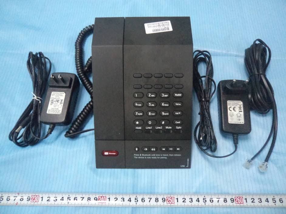
Click to zoom
Application Details
- Equipment Class
- DSS - Part 15 Spread Spectrum Transmitter
- Date of Grant
- Nov 24, 2014
- Application Purpose
- Original Equipment
- Date of Application
- Nov 24, 2014
- Equipment Note
- Corded telephone with BT function
- Frequency Range
- 2402.00000000 - 2480.00000000
- Company
- CETIS,INC.
- Country
- United States
Documents & Files
Document Text
Text extracted from the exhibit documents filed with the FCC. Open a document above to read the original.
Users Manual
M Series Multimedia Phone User Guide Thank you for buying the M series multimedia phone from Cetis! Thank you for buying the superior M series multimedia phone fro m Cetis. Cetis is the founder of global hotel tel ephony and moreover the appointed standard for the guestroom telephone in star hotel. We provide the unique warranty service for the telephone . If you have any question about the telephone or warranty, pleas e contact us. We pay our gratit ude for your purchase. This user guide is only for your reference. When the change occ urs due to the version update, Cetis reserves the right of final interpretation. Contents Installation Installation‐‐‐‐‐‐‐‐‐‐‐‐‐‐‐‐‐‐‐‐‐‐‐‐‐‐‐‐‐‐‐‐‐‐‐‐‐‐‐‐‐‐‐‐‐‐‐‐‐‐‐ ‐‐‐‐‐‐‐‐‐‐‐‐‐‐‐‐‐‐‐‐‐‐‐‐‐‐‐‐‐‐‐‐‐‐‐‐‐‐‐‐‐‐‐‐‐‐‐‐‐‐2 Installation Prompts‐‐‐‐‐‐‐‐‐‐‐‐‐‐‐‐‐‐‐‐‐‐‐‐‐‐‐‐‐‐‐‐‐‐‐‐‐‐‐‐‐‐‐ ‐‐‐‐‐‐‐‐‐‐‐‐‐‐‐‐‐‐‐‐‐‐‐‐‐‐‐‐‐‐‐‐‐‐‐‐‐‐‐‐‐‐‐‐‐‐‐2 Setting Line Voltage Selection‐‐‐‐‐‐‐‐‐‐‐‐‐‐‐‐‐‐‐‐‐‐‐‐‐‐‐‐‐‐‐‐‐‐‐‐‐‐‐‐‐ ‐‐‐‐‐‐‐‐‐‐‐‐‐‐‐‐‐‐‐‐‐‐‐‐‐‐‐‐‐‐‐‐‐‐‐‐‐‐‐‐‐‐‐‐‐‐‐3 Message Waiting Selection‐‐‐‐‐‐‐‐‐‐‐‐‐‐‐‐‐‐‐‐‐‐‐‐‐‐‐‐‐‐‐‐‐‐‐‐‐‐ ‐‐‐‐‐‐‐‐‐‐‐‐‐‐‐‐‐‐‐‐‐‐‐‐‐‐‐‐‐‐‐‐‐‐‐‐‐‐‐‐‐‐‐‐3 Operation Volume‐‐‐‐‐‐‐‐‐‐‐‐‐‐‐‐‐‐‐‐‐‐‐‐‐‐‐‐‐‐‐‐‐‐‐‐‐‐‐‐‐‐‐‐‐‐‐‐‐‐‐‐‐‐‐‐‐ ‐‐‐‐‐‐‐‐‐‐‐‐‐‐‐‐‐‐‐‐‐‐‐‐‐‐‐‐‐‐‐‐‐‐‐‐‐‐‐‐‐‐‐‐‐‐‐‐‐3 Indicator‐‐‐‐‐‐‐‐‐‐‐‐‐‐‐‐‐‐‐‐‐‐‐‐‐‐‐‐‐‐‐‐‐‐‐‐‐‐‐‐‐‐‐‐‐‐‐‐‐‐‐‐‐‐ ‐‐‐‐‐‐‐‐‐‐‐‐‐‐‐‐‐‐‐‐‐‐‐‐‐‐‐‐‐‐‐‐‐‐‐‐‐‐‐‐‐‐‐‐‐‐‐‐‐‐4 Function Keys ‐‐‐‐‐‐‐‐‐‐‐‐‐‐‐‐‐‐‐‐‐‐‐‐‐‐‐‐‐‐‐‐‐‐‐‐‐‐‐‐‐‐‐‐‐‐‐‐‐‐‐‐‐‐‐‐‐‐‐‐‐‐‐ ‐‐‐‐‐‐‐‐‐‐‐‐‐‐‐‐‐‐‐‐‐‐‐‐‐‐‐‐‐‐‐‐‐4 Making a Call Making a Call with Handset‐‐‐‐‐‐‐‐‐‐‐‐‐‐‐‐‐‐‐‐‐‐‐‐‐‐‐‐‐‐‐‐‐‐‐‐‐ ‐‐‐‐‐‐‐‐‐‐‐‐‐‐‐‐‐‐‐‐‐‐‐‐‐‐‐‐‐‐‐‐‐‐‐‐‐‐‐‐‐‐‐5 Making a Call with Han dset or Speakerphone‐‐‐‐‐‐‐‐‐‐‐‐‐‐‐‐‐‐‐‐‐ ‐‐‐‐‐‐‐‐‐‐‐‐‐‐‐‐‐‐‐‐‐‐‐‐‐‐‐‐‐‐‐‐‐‐‐‐5 Making a Call with Speakerphone ‐‐‐‐‐‐‐‐‐‐‐‐‐‐‐‐‐‐‐‐‐‐‐‐‐‐‐‐‐‐‐ ‐‐‐‐‐‐‐‐‐‐‐‐‐‐‐‐‐‐‐‐‐‐‐‐‐‐‐‐‐‐‐‐‐‐‐‐‐‐‐‐6 Programming Speed Dial Memory Key and Flash Programming ‐‐‐‐‐‐‐‐‐‐‐‐‐‐‐‐‐‐‐ ‐‐‐‐‐‐‐‐‐‐‐‐‐‐‐‐‐‐‐‐‐‐‐‐‐‐‐‐‐‐‐‐‐6 Storing a Number into a Speed Dial Key‐‐‐‐‐‐‐‐‐‐‐‐‐‐‐‐‐‐‐‐‐‐‐‐‐ ‐‐‐‐‐‐‐‐‐‐‐‐‐‐‐‐‐‐‐‐‐‐‐‐‐‐‐‐‐‐‐‐‐‐‐‐‐‐‐6 Flash Time Programming ‐‐‐‐‐‐‐‐‐‐‐‐‐‐‐‐‐‐‐‐‐‐‐‐‐‐‐‐‐‐‐‐‐‐‐‐‐‐‐‐ ‐‐‐‐‐‐‐‐‐‐‐‐‐‐‐‐‐‐‐‐‐‐‐‐‐‐‐‐‐‐‐‐‐‐‐‐‐‐‐‐‐‐6 “Flash” Off‐hooking ‐‐‐‐‐‐‐‐‐‐‐‐‐‐‐‐‐‐‐‐‐‐‐‐‐‐‐‐‐‐‐‐‐‐‐‐‐‐‐‐‐‐‐ ‐‐‐‐‐‐‐‐‐‐‐‐‐‐‐‐‐‐‐‐‐‐‐‐‐‐‐‐‐‐‐‐‐‐‐‐‐‐‐‐‐‐‐‐‐‐7 Bluetooth Function Setting the Name‐‐‐‐‐‐‐‐‐‐‐‐‐‐‐‐‐‐‐‐‐‐‐‐‐‐‐‐‐‐‐‐‐‐‐‐‐‐‐‐‐‐‐‐‐‐‐ ‐‐‐‐‐‐‐‐‐‐‐‐‐‐‐‐‐‐‐‐‐‐‐‐‐‐‐‐‐‐‐‐‐‐‐‐‐‐‐‐‐‐‐‐‐‐7 Device Pairing and Use‐‐‐‐‐‐‐‐‐‐‐‐‐‐‐‐‐‐‐‐‐‐‐‐‐‐‐‐‐‐‐‐‐‐‐‐‐‐‐‐‐ ‐‐‐‐‐‐‐‐‐‐‐‐‐‐‐‐‐‐‐‐‐‐‐‐‐‐‐‐‐‐‐‐‐‐‐‐‐‐‐‐‐‐‐‐7 Trouble Shooting ‐‐‐‐‐‐‐‐‐‐‐‐‐‐‐‐‐‐‐‐‐‐‐‐‐‐‐‐‐‐‐‐‐‐‐‐‐‐‐‐‐‐‐‐‐‐‐‐‐‐‐‐‐‐‐‐‐‐‐‐‐‐‐ ‐‐‐‐‐‐‐‐‐‐‐‐‐‐‐‐‐‐‐‐‐‐‐‐‐‐‐‐17 Global Head Office: 5025 Galley Road Colorado Springs, Co 80915 USA Head Office Website: www.CetisGroup.com The Appointed Standard for the Guestroom Telephone in Global Star Hotels The Founder of Global Hotel Telephony 1 Unpacking your telephone: Verify that the package contains the following supplied items: Telephone base unit Handset Power adaptor 10’coiled handset cord 15’straight line cord Installation The M series telephone is designed for use behind a registered PBX system. The telephone user or system installer must supply an RJ‐11 modular wall jack to c onnect this telephone to the PBX system. The PBX “station port” type must be “Industry Standard Analog” or “POTS.” This telephone cannot be used with “ digital” PBX station ports. Connect the one end of supplied coiled handset cord to Handset jack on the left side in the front of base unit. Connect the free end of the coiled handset cord to t he jack on the left side of handset. Place the handset in its cradle. Connect the supplied straight modular cord to the TEL LINE jack located on the FRONT of the telephone. Connect the remaining e nd of this cord to the telephone system RJ‐11 wall jack. Lift the handset and verify that dial tone is present. Caution • Never install telephone wiring during a lightning storm. • Never install telephone jacks in wet locations unless the jac k is specifically designed for wet locations. • Never touch uninstalled telephone wires or terminals unless t he telephone line has been disconnected at the network interface. • Use caution when installing or modifying telephone lines. Setting Line Voltage Selectors The M series is designed to operate behind PBX telephone system s rated between 24 volts and 48 volts. The line voltage selectio n of telephone uses the auto de tect, without needing to set the switches. Message Waiting Selectors This telephone automat ically responds to both “NEON” or low‐vol tage “LED” signals via the “TYPE” setting which is the defa ult at factory. If the reverse polarity message signaling is selected, just move the MW switch to “LR1” or “LR2” (LR means “line rever se”). Operation Volume... Handset & Speaker Volume Control The volume control key increases or decreases the volume of the handset and speaker. When the handset is off hook or speaker key engaged on speakerp hones, press “Vol ” and “Vol ” key to increase or decrease the volume. Both the hands et and speaker volume control is a 5‐step operation. The handsets of all models are hearing aid compatible. Ringer Volume Control The ringer volume control shares the same “Vol ” and “Vol ” ke y. To adjust the ringer volume : when the phone is at standby mode, press “Vol ” to increase th e ringer volume and press “Vol ” key to decrease the ringer volume. Indicators... Speaker, Mute Status Indicator, Line Indicator and Bluetooth Indicator Speakerphones are equipped with L ED indicators to show the curr ent feature key status. Press Speaker or Mute Feature Key to use that service ‐ LED wil l light Red when that key is IN USE. 2 3 The line indicator shows the cur rent status of that line ‐ LED will light Red when that line is IN USE. The red LED keeps blinking when the line is on hold. Press and hold “ ” key, a “toot” prompt sound will be heard. The BT LED keeps bl inking at 1S on and 1S off. This represents that the Bluetooth is initiated, an d other device can locate it for pairing and using …
Text truncated - open the document above for the full version.
Cover Letter(s)
Cetis, Inc. Address: 5025 Galley Road, Colorado Springs CO, 80915, USA Tel: (719) 571-9231 Fax: (719) 638-8815 FCC Confidential Authorization 12/3/2014 FEDERAL COMMUNICATIONS COMMISSIONS Authorization and Evaluation Division 7435 Oakland Mills Road Columbia, MD 21046 Confidentiality Request regarding application for certification of FCC ID: ZTUM200B10 Pursuant to Sections 0.457 and 0.459 of the Commission’s Rules, we hereby request confidential treatment of information accompanying this application as outlined below: § Block Diagram--- (Long term) § Circuit Description--- (Long term) § Detailed Circuit Schematics of EUT--- (Long term) The above materials contain trade secrets and proprietary information not customarily released to the public. The public disclosure of these materials may be harmful to the applicant and provide unjustified benefits to its competitors. The applicant understands that pursuant to Section 0.457 of the Rules, disclosure of this application and all accompanying documentation will not be made before the date of the grant for this application. Sincerely Yours, Bing Sun President & CEO
External Photos
EXHIBIT B - EUT EXTERNAL PHOTOGRAPHS EUT – All View EUT – Front View EUT – Rear View EUT – Top View EUT – Bottom View EUT – Left View EUT – Right View EUT – Adapter Label View
ID Label/Location Info
EXHIBIT A - FCC ID LABEL AND LOCATION FCC ID Label FCC ID Label Location Information The label shown shall be permanently affixed at a conspicuous location on the device and be readily visible to the user at the time purchase (Labeling requirements per 2.925)
Internal Photos
EUT – INTERNAL PHOTOGRAPHS EUT (Base) – Cover off View 1 EUT (Base) – Cover off View 2 EUT (Base) – Cover off View 3 EUT (Base) – Main Board 1 Top View EUT (Base) – Main Board 1 Bottom View EUT (Base) – Main Board 2 Top View EUT (Base) – Main Board 2 Bottom View EUT (Base) – Keyboard Top View EUT (Base) – Keyboard Bottom View EUT (Base) – Subboard 1 Top View EUT (Base) – Subboard 1 Bottom View EUT (Base) – Subboard 2 Top View BT Antenna EUT (Base) – Subboard 2 Bottom View EUT (Base) – Subboard 3 Top View EUT (Base) – Subboard 3 Bottom View EUT (Handset) – Cover off View
Test Report
Note: This test report is prepared for the customer shown above and for the equipment described herein. It may not be duplicated or used in part without prior written consent from Bay Area Compliance Laboratories Corp. FCC PART 15.247 TEST REPORT For CETIS, INC. 5025 GALLEY ROAD, COLORADO SPRINGS, CO 80915 USA FCC ID: ZTUM200B10 Report Type: Original Report Product Type: Corded Telephone with BT Function Test En gineer: Gardon Zhang Re port Number: RSZ140422010-00 Re port Date: 2014-10-09 Reviewed B y: Jimmy Xiao RF En gineer Prepared By: Bay Area Compliance Laboratories Corp. (Shenzhen) 6/F, the 3rd Phase of WanLi Industrial Building ShiHua Road, FuTian Free Trade Zone Shenzhen, Guangdong, China Tel: +86-755-33320018 Fax: +86-755-33320008 www.baclcorp.com.cn Bay Area Compliance Laboratories Corp. (Shenzhen) Report No.: RSZ140422010-00 FCC Part 15.247 Page 2 of 64 TABLE OF CONTENTS GENERAL INFORMATION ....................................................................................................................................... 4 PRODUCT DESCRIPTION FOR EQUIPMENT UNDER TEST (EUT) ..................................................................................... 4 OBJECTIVE ................................................................................................................................................................... 4 RELATED SUBMITTAL(S)/GRANT(S) ............................................................................................................................. 4 TEST METHODOLOGY .................................................................................................................................................. 4 TEST FACILITY ............................................................................................................................................................. 5 SYSTEM TEST CONFIGURATION .......................................................................................................................... 6 DESCRIPTION OF TEST CONFIGURATION ...................................................................................................................... 6 EUT EXERCISE SOFTWARE .......................................................................................................................................... 6 SPECIAL ACCESSORIES ................................................................................................................................................. 6 EQUIPMENT MODIFICATIONS ....................................................................................................................................... 6 SUPPORT EQUIPMENT LIST AND DETAILS .................................................................................................................... 6 EXTERNAL I/O CABLE .................................................................................................................................................. 6 BLOCK DIAGRAM OF TEST SETUP ................................................................................................................................ 7 SUMMARY OF TEST RESULTS ............................................................................................................................... 8 FCC §15.247 (i) & §2.1093 – RF EXPOSURE ............................................................................................................ 9 APPLICABLE STANDARD .............................................................................................................................................. 9 FCC §15.203 – ANTENNA REQUIREMENT .......................................................................................................... 10 APPLICABLE STANDARD ............................................................................................................................................ 10 ANTENNA CONNECTOR CONSTRUCTION .................................................................................................................... 10 FCC §15.207 (a) – AC LINE CONDUCTED EMISSIONS ..................................................................................... 11 APPLICABLE STANDARD ............................................................................................................................................ 11 MEASUREMENT UNCERTAINTY .................................................................................................................................. 11 EUT SETUP ................................................................................................................................................................ 11 EMI TEST RECEIVER SETUP ....................................................................................................................................... 12 TEST PROCEDURE ...................................................................................................................................................... 12 TEST EQUIPMENT LIST AND DETAILS ......................................................................................................................... 12 CORRECTED FACTOR & MARGIN CALCULATION ....................................................................................................... 12 TEST RESULTS SUMMARY .......................................................................................................................................... 13 TEST DATA ................................................................................................................................................................ 13 FCC §15.205, §15.209 & §15.247(d) – RADIATED EMISSIONS ........................................................................... 16 APPLICABLE STANDARD ............................................................................................................................................ 16 MEASUREMENT UNCERTAINTY .…
Text truncated - open the document above for the full version.
Test Setup Photos
EXHIBIT D - TEST SETUP PHOTOGRAPHS Conducted Emissions - Front View Conducted Emissions - Side View Radiated Emissions – Front View (30-1000 MHz) Radiated Emissions – Rear View (30-1000 MHz) Radiated Emissions – Front View (1-25 GHz) Radiated Emissions – Rear View (1-25 GHz)
Contact Information
Applicant
Brock E Munsell(Chief Technology Officer)
Test Firm
Bay Area Compliance Laboratory Corp. (Shenzhen)John Chan
Technical Specifications
| # | Rule Parts | Frequency Range | Power Output |
|---|---|---|---|
| 1 | 15C | 2.40 GHz - 2.48 GHz | 2.30 mW |
Other Applications from CETIS,INC.

ZTU-V103IP
Jul 07, 2026Cordless IP Phone
Equipment Class
PUB - Part 15 Unlicensed PCS Base Station
ZTU-V103
Jul 06, 2026Cordless Phone
Equipment Class
PUB - Part 15 Unlicensed PCS Base Station
ZTU-V103IPHDKIT
Jul 06, 2026Cordless IP Phone
Equipment Class
PUE - Part 15 Unlicensed PCS portable Tx held to ear
ZTU-9702HDKIT
May 17, 2020Cordless Phone
Equipment Class
PUE - Part 15 Unlicensed PCS portable Tx held to ear
ZTU-9702IPMWD
May 03, 2020VOIP Phone
Equipment Class
PUB - Part 15 Unlicensed PCS Base Station