ZUBWIFI-601WiFi video door phone
Shenzhen Zhuohao Intelligent Electronic Development Co., Ltd.
Click to zoom
Application Details
- Equipment Class
- DTS - Digital Transmission System
- Date of Grant
- Nov 16, 2014
- Application Purpose
- Original Equipment
- Date of Application
- Nov 16, 2014
- Equipment Note
- WiFi video door phone
- Frequency Range
- 2412.00000000 - 2462.00000000
- Country
- China
Documents & Files
Document Text
Text extracted from the exhibit documents filed with the FCC. Open a document above to read the original.
Users Manual
This device complies with part 15 of the FCC Rules. Operation is subject to the following two conditions: (1) This device may not cause harmful interference, and (2) this device must accept any interference received, including interference that may cause undesired operation Note: This equipment has been tested and found to comply with the limits for a Class B digital device, pursuant to part 15 of the FCC Rules. These limits are designed to provide reasonable protection against harmful interference in a residential installation. This equipment generates uses and can radiate radio frequency energy and, if not installed and used in accordance with the instructions, may cause harmful interference to radio communications. However, there is no guarantee that interference will not occur in a particular installation. If this equipment does cause harmful interference to radio or television reception, which can be determined by turning the equipment off and on, the user is encouraged to try to correct the interference by one or more of the following measures: -Reorient or relocate the receiving antenna. -Increase the separation between the equipment and receiver. -Connect the equipment into an outlet on a circuit different from that to which the receiver is connected. -Consult the dealer or an experienced radio/TV technician for help. Any Changes or modifications not expressly approved by the party responsible for compliance could void the user's authority to operate the equipment. This equipment complies with FCC radiation exposure limits set forth for an uncontrolled environment. 目录 Contents Contents 1 1、Introduce of product 1 2、Installation 2 3 3、Port definition 3 4 4、Operate Explanation 4 5 5、Doorbell Setting 5 5 5.1、Add doorbell settings 5 6 5.2、System settings 6 7 5.3、White list settings 7 8 5.4、Alarm settings 8 9 5.5、Equipment clock settings 9 9 5.6、Interface settings 9 10 5.7、Wifi settings 10 11 6、Introduce of functions 11 12 6.1、Intercom 12 13 6.2、Monitor 13 14 6.3、Real-time Alerts 14 15 6.4、Video replay 15 16 6.5、Local pictures 16 17 6. 6、Visitors/Alarm record 17 18 7、Software system settings 18 19 8、Specification of product 19 20 9、Components 20 Contents 1、Introduce of product 2、Installation 3、Port definition 4、Operate Explanation 5、Doorbell Setting 5.1、Add doorbell settings 5.2、System settings 5.3、White list settings 5.4、Alarm settings 5.5、Equipment clock settings 5.6、Interface settings 5.7、Wifi settings 6、Introduce of functions 6.1、Intercom 6.2、Monitor 6.3、Real-time Alerts 6.4、Video replay 6.5、Local pictures 6. 6、Visitors/Alarm record 7、Software system settings 8、Specification of product 1 2 3 4 5 5 6 7 8 9 9 10 11 11 12 13 14 15 16 17 18 19 9、Components 1 1. Introduce of product Wifi Visual intercom doorbell is a doorbell with wifi connected camera . It connect with home wifi to achieve two-way intercom between doorbell and cell phone .When visitors press the doorbell ,doorbell sounds and meanwhile camera will start to work sending real-time video and call to smart phone . User receive the call and see the video to check who is outside ,can intercom with visitors and remotely unlock door etc . Wifi Visual intercom doorbell have alarm and motion detector functions, make your home security has more powerful barrier . Advance infrared light design make users can distinguish the visitors in the evening. AC/DC power supply , eliminate the troubles of frequenty replacing battery . 2.4G wifi transmission systems , real-time video transmission , Audio and video data transmission up to 100M at most , Support Android OS . One doorbell can support 10 pcs cell phone at most . Make you see the outdoor anytime anywhere with wifi/3g/4g internet . Pass CE , RoHS certification Thank you for your support of this products , your satisfaction is our aim ! 1 2、Installstion Diagram 1. Switch four screws in the top part and bottom part . Open the cover from middle position ,connect 12V/1A power wire . 2. Fix the doorbell and 86 box with screws 3. Cover up the cover just opened , and install the 4 screws to finish . 2 3、Port Deflnatlon 3 3.1.Initial Installation( set door camera to connect with smart phone) 初次操作 4 三.Operate explanation 1. According to the installation diagram and connection diagram install doorbell , connect to power and lock . 2. Wait about one minutes , after speak “successfully start system , welcome to use “ , doorbell start successful can normal working . 3. Cellphone Configuration : 1.Install wifi door phone APP in cellphone . Press the doorbell button above 3 seconds , Doorbell enter in Configuration model , and give a notice “Network configuration model now , set it down in 5mins’’. 2.Open cell phone wifi , connect to the hot spot named “BELL-00******”, Initial password is 123456789,.After connecting successful , open wifi door phone app again , press “ Add doorbell” , then click search or shake cellphone ,when smart phone show a ID number , Click the id number , then click “done” icon to finish. 3. First connected cellphone Defaults to the administrator. If need to add cellphone user , set up at administrator cellphone phone .Enter into white list setting add user name and password . 4. Network Configuration : 1. Enter into wifi settings , add home wifi ,click “done” to finish 2. Insert internet cable to LAN port directly ,wifi setting is no need 5. Change administrator password : administrator cellphone enter into white list settings , click “admin user “, put into password click “done”to finish .Notice :After set up administrator password , need to delete doorbell and add again by new password . Or cell phone will notice wrong password . 6. Each time connect to power, press the doorbell button above 10S , can restore factory settings . ACTOP 5、The bell set 5.1、Add door bell 5 5.2、System settings 1.Voice prompt switch : turn on or turn off . Turn on by factory settings. 2.Configuration mode switch: turn on or turn off .Turn on by factory settings. 3.Monitoring the maximum length …
Text truncated - open the document above for the full version.
Cover Letter(s)
Shenzhen Zhuohao Intelligent Electronic Development Co., Ltd. FCC Confidentiality Request Number: CF303 Version: V01 Date: 01-02-2010 To the FCC and FCC TCB handling this application for certification Pursuant to 47 CFR Section 0.459(a) & (b), we, (the applicant / grantee) Company name Shenzhen Zhuohao Intelligent Electronic Development Co., Ltd. Addresss 5F, Building B2, Shangrong Industry Zone, Baolong 5th Road, Longgang District City Shenzhen Country China request non-disclosure and confidential treatment for our certification under: Grantee Code Product Number FCC ID: ZUB WIFI-601 of the following materials submitted within this certification application: (please cross what is applicable, or add other documents) x Operational Description x Block Diagrams x Schematics Diagrams Bill of Materials Above materials contain secrets, proprietary and technical information, which would customarily be guarded from competitors under 47 CFR, section 0.457(d)(2). Disclosure or publication or any portion of this company confidential material to other parties could cause substantial competitive harm and provide unjustified benefits for competitors. We understand that pursuant to 47 CFR section 0.457(d)(1)(ii) disclosure of the applicant and all accompanying documentation will not be made before the date of the grant. Attestation: City and Country: Date: Name: (this must be a person) Function: Signature: (or official company stamp) SHENZHEN 2014.11.02 Zhenhai Zhou MANAGER
Cover Letter(s)
Shenzhen Zhuohao Intelligent Electronic Development Co., Ltd. 5F, Building B2, Shangrong Industry Zone, Baolong 5th Road, Longgang District Shenzhen China Date: Nov. 12, 2014 FCC ID: ZUBWIFI-601 Subject: Ad Hoc Mode Function Declaration To Whom it may concern, This device is acting as slave and operating in the 2.4 GHz (2412 – 2462 MHz) band.Ad Hoc function is supported but not able to operate on non-US frequencies.Please contact the one signed below or the authorized agent for this filing. Regards, Yours sincerely, Signatory Signature Name: Zhenhai Zhou Title: Manager Tel: 0755-28574903
External Photos
APPENDIX-PHOTOGRAPHS OF EUT CONSTRUCTIONAL DETAILS Photo 1 Photo 2 Photo 3 Photo 4 Photo 5 Photo 6 Photo 7
ID Label/Location Info
FCC ID LABELING AND LOCATION FCC ID Label WiFi video door phone Model NO.: WiFi-601 Input Rating: DC 12V FCC ID: ZUBWIFI-601 Shenzhen Zhuohao Intelligent Electronic Development Co., Ltd. Made in China FCC ID Label Location The label shown shall be permanently affixed at a conspicuous location on the device and be readily visible to the user at the time purchase (Labeling requirements per 2.925)
Internal Photos
Photo 8 Photo 9 Photo 10 Photo 11 Photo 12 Photo 13 Photo 14 Photo 15 ANT
RF Exposure Info
FCC ID : ZUBWIFI-601 RF EXPOSURE EVALUATION METHOD SAR Test Exclusion Thresholds for 100 MHz – 6 GHz and ≤ 50 mm Approximate SAR Test Exclusion Power Thresholds at Selected Frequencies and Test Separation Distances are illustrated in the following Table. The 1-g and 10-g SAR test exclusion thresholds for 100 MHz to 6 GHz at test separation distances ≤ 50 mm are determined by: [(max. power of channel, including tune-up tolerance, mW)/(min. test separation distance, mm)] · [√f(GHz)] ≤ 3.0 for 1-g SAR and ≤ 7.5 for 10-g extremity SAR,where f(GHz) is the RF channel transmit frequency in GHz Power and distance are rounded to the nearest mW and mm before calculation The result is rounded to one decimal place for comparison The test exclusions are applicable only when the minimum test separation distance is ≤ 50 mm and for transmission frequencies between 100 MHz and 6 GHz. When the minimum test separation distance is < 5 mm, a distance of 5 mm is applied to determine SAR test exclusion. Maximum measured transmitter power. 802.11b Test Channel Frequency (MHz) AV Output Power (dBm) AV Output Power (mW) CH01 2412 9.41 8.73 CH06 2437 9.65 9.23 CH11 2462 9.54 9.00 802.11g CH01 2412 8.57 7.19 CH06 2437 8.66 7.35 CH11 2462 8.64 7.31 802.11n(H20) CH01 2412 7.36 5.45 CH06 2437 7.58 5.73 CH11 2462 7.61 5.77 Remark: The best case gain of the antenna is 2.5dBi. 2.5 dBi logarithmic terms convert to numeric result is nearly 1.78 The 1-g and 10-g SAR test exclusion thresholds for 100 MHz to 6 GHz at test separation distances ≤ 50 mm are determined by: [(max. power of channel, including tune-up tolerance, mW)/(min. test separation FCC ID : ZUBWIFI-601 distance,mm)] · [√f(GHz)] Mode [(max. power of channel, including tune- up tolerance, mW) (min. test separation distance,mm)] [√f(GHz)] ResultLimit 802.11b CH01 9.5 5 2.412 2.951 3 CH06 9.5 5 2.437 2.966 3 CH11 9.5 5 2.462 2.981 3 802.11g CH01 9.5 5 2.412 2.951 3 CH06 9.5 5 2.437 2.966 3 CH11 9.5 5 2.462 2.981 3 802.11g CH01 9.5 5 2.412 2.951 3 CH06 9.5 5 2.437 2.966 3 CH11 9.5 5 2.462 2.981 3 The test Result is less than 3.0 for 1-g SAR and ≤ 7.5 for 10-g extremity SAR. Conclusion: No SAR is required.
Test Report
Report No. ATT-2014SZ1031058F - Page 1 of 67 - FCC RADIO TEST REPORT FCC ID: ZUBWIFI-601 Product: WiFi video door phone Trade Name: N/A Model Name: WiFi-601 Serial Model: N/A Prepared for Shenzhen Zhuohao Intelligent Electronic Development Co., Ltd. 5F, Building B2, Shangrong Industry Zone, Baolong 5th Road, Longgang District, Shenzhen, China Prepared by Shenzhen Asia Test Technology Co.,Ltd. 1/6, Bldg.8, Zhonghua Industrial City, Chuangye Rd., Nanshan District, Shenzhen, Guangdong, China Report No. ATT-2014SZ1031058F - Page 2 of 67 - TEST RESULT CERTIFICATION Applicant’s name........ Shenzhen Zhuohao Intelligent Electronic Development Co., Ltd. Address ........................ 5F, Building B2, Shangrong Industry Zone, Baolong 5th Road, Longgang District, Shenzhen, China Manufacture's Name... Shenzhen Zhuohao Intelligent Electronic Development Co., Ltd. Address ........................ 5F, Building B2, Shangrong Industry Zone, Baolong 5th Road, Longgang District, Shenzhen, China Product description Product name .................WiFi video door phone Model and/or type reference ..................... WiFi-601 Serial Model .................... N/A Standards.................... FCC Part15.247 Test procedure ................ ANSI C63.4-2003 This device described above has been tested by ATT, and the test results show that the equipment under test (EUT) is in compliance with the FCC requirements. And it is applicable only to the tested sample identified in the report. This report shall not be reproduced except in full, without the written approval of ATT, this document may be altered or revised by ATT, personal only, and shall be noted in the revision of the document. Date of Test...................................... Date (s) of performance of tests ....... Oct 31, 2014 ~ Nov 12, 2014 Date of Issue..................................... Nov 12, 2014 Test Result......................................... Pass Testing Engineer : (Eric Wang) Technical Manager : (Jerry You) Authorized Signatory : (Jack yu) Report No. ATT-2014SZ1031058F - Page 3 of 67 - Table of Contents Page 1 . SUMMARY OF TEST RESULTS 5 1.1 TEST FACILITY 6 1.2 MEASUREMENT UNCERTAINTY 6 2 . GENERAL INFORMATION 7 2.1 GENERAL DESCRIPTION OF EUT 7 2.2 DESCRIPTION OF TEST MODES 8 2.3 BLOCK DIGRAM SHOWING THE CONFIGURATION OF SYSTEM TESTED 9 2.4 DESCRIPTION OF SUPPORT UNITS(CONDUCTED MODE) 10 2.5 EQUIPMENTS LIST FOR ALL TEST ITEMS 11 3 . EMC EMISSION TEST 12 3.1 CONDUCTED EMISSION MEASUREMENT 12 3.1.1 POWER LINE CONDUCTED EMISSION LIMITS 12 3.1.2 TEST PROCEDURE 13 3.1.3 DEVIATION FROM TEST STANDARD 13 3.1.4 TEST SETUP 13 3.1.5 EUT OPERATING CONDITIONS 13 3.1.6 TEST RESULTS 14 3.2 RADIATED EMISSION MEASUREMENT 16 3.2.1 RADIATED EMISSION LIMITS 16 3.2.2 TEST PROCEDURE 17 3.2.3 DEVIATION FROM TEST STANDARD 17 3.2.4 TEST SETUP 18 3.2.5 EUT OPERATING CONDITIONS 19 3.2.6 TEST RESULTS (BETWEEN 9KHZ – 30 MHZ) 20 3.2.7 TEST RESULTS (BETWEEN 30MHZ – 1GHZ) 21 3.2.8 TEST RESULTS (ABOVE 1000 MHZ) 22 4 . POWER SPECTRAL DENSITY TEST 41 4.1 APPLIED PROCEDURES / LIMIT 41 4.1.1 TEST PROCEDURE 41 4.1.2 DEVIATION FROM STANDARD 41 4.1.3 TEST SETUP 41 4.1.4 EUT OPERATION CONDITIONS 41 4.1.5 TEST RESULTS 42 5 . BANDWIDTH TEST 49 Report No. ATT-2014SZ1031058F - Page 4 of 67 - Table of Contents Page 5.1 APPLIED PROCEDURES / LIMIT 49 5.1.1 TEST PROCEDURE 49 5.1.2 EUT OPERATION CONDITIONS 49 5.1.3 TEST RESULTS 50 6 . PEAK OUTPUT POWER TEST 58 6.1 APPLIED PROCEDURES / LIMIT 58 6.1.1 TEST PROCEDURE 58 6.1.2 DEVIATION FROM STANDARD 58 6.1.3 TEST SETUP 58 6.1.4 EUT OPERATION CONDITIONS 58 6.1.5 TEST RESULTS 59 7 . 100 KHZ BANDWIDTH OF FREQUENCY BAND EDGE 60 7.1 DEVIATION FROM STANDARD 60 7.2 TEST SETUP 60 7.3 EUT OPERATION CONDITIONS 60 7.4 TEST RESULTS 61 8 . ANTENNA REQUIREMENT 65 8.1 STANDARD REQUIREMENT 65 8.2 EUT ANTENNA 65 9 . EUT TEST PHOTO 66 APPENDIX-PHOTOGRAPHS OF EUT CONSTRUCTIONAL DETAILS Report No. ATT-2014SZ1031058F - Page 5 of 67 - 1. SUMMARY OF TEST RESULTS Test procedures according to the technical standards: FCC Part15 (15.247) , Subpart C Standard Section Test Item Judgment Remark 15.207 Conducted Emission PASS 15.247 (a)(2) 6dB Bandwidth PASS 15.247 (b) Peak Output Power PASS 15.247 (c) Radiated Spurious Emission PASS 15.247 (d) Power Spectral Density PASS 15.205 Band Edge Emission PASS 15.203 Antenna Requirement PASS NOTE: (1)” N/A” denotes test is not applicable in this Test Report Report No. ATT-2014SZ1031058F - Page 6 of 67 - 1.1 TEST FACILITY Shenzhen STONE Testing Technology Co.,Ltd. Add.: F/6, Bldg.12, Zhongxing Industrial City, Chuangye Rd., Nanshan District Shenzhen P.R. China FCC Registration No.: 323508; IC Registration No.: 11043A 1.2 MEASUREMENT UNCERTAINTY The reported uncertainty of measurement y ± U,where expended uncertainty U is based on a standard uncertainty multiplied by a coverage factor of k=2,providing a level of confidence of approximately 95 %。 No. Item Uncertainty 1 Conducted Emission Test ±1.38dB 2 RF power,conducted ±0.16dB 3 Spurious emissions,conducted ±0.21dB 4 All emissions,radiated(<1G) ±4.68dB 5 All emissions,radiated(>1G) ±4.89dB 6 Temperature ±0.5°C 7 Humidity ±2% Report No. ATT-2014SZ1031058F - Page 7 of 67 - 2. GENERAL INFORMATION 2.1 GENERAL DESCRIPTION OF EUT Equipment WiFi video door phone Model Name WiFi-601 Serial Model N/A Model Difference N/A WIFI Supported type: 802.11b/802.11g/802.11n(H20) Modulation: 802.11b: DSSS 802.11g/802.11n(H20): OFDM Operation frequency: 802.11b/802.11g/802.11n(H20): 2412MHz~2462MHz Channel number: 802.11b/802.11g/802.11n(H20): 11 Channel separation: 5MHz Antenna type: Internal Antenna Antenna gain: 2.5 dBi Ratings DC 12V by adapter Adapter Model:DLL05122000 Input:100-240V,50/60Hz, 0.55A Output:12V , 2A Battery N/A Connecting I/O Port(s) Please refer to the User's Manual Channel List for 802.11b/g/n(H20) Channel Frequency (MHz) Channel Frequency (MHz)ChannelFrequency (MHz)Channel Frequency (MHz) 01 2412 04 2427 07 2442 10 2457 02 2417 05 2432 08 2447 11 2462 03 2422 06 2437 09 …
Text truncated - open the document above for the full version.
Test Setup Photos
Report No. ATT-2014SZ1031058F - Page 66 of 67 - 9. EUT TEST PHOTO Radiated Measurement Photos Report No. ATT-2014SZ1031058F - Page 67 of 67 - Conducted Measurement Photos
Contact Information
Applicant
Zhenhai Zhou(Manager)
Test Firm
Shenzhen STONE Testing Technology Co.,Ltd.Ethan Chen
[email protected]8607552658
Technical Specifications
| # | Rule Parts | Frequency Range | Power Output |
|---|---|---|---|
| 1 | 15C | 2.41 GHz - 2.46 GHz | 23.70 mW |
Other Applications from Shenzhen Zhuohao Intelligent Electronic Development Co., Ltd.
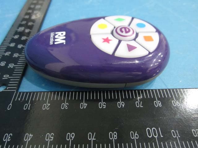
ZUBRM18588TX
Aug 17, 2011RM Easirespond
Equipment Class
DXT - Part 15 Low Power Transceiver, Rx Verified
ZUBRM18585RX
Aug 16, 2011RM Easirespond
Equipment Class
DXT - Part 15 Low Power Transceiver, Rx Verified