ZVA04BT Module
Tonly Technology Co., Ltd.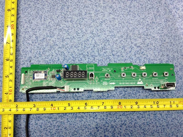
Click to zoom
Application Details
- Equipment Class
- DSS - Part 15 Spread Spectrum Transmitter
- Date of Grant
- Jan 27, 2014
- Application Purpose
- Original Equipment
- Date of Application
- Jan 27, 2014
- Equipment Note
- BT Module
- Frequency Range
- 2402.00000000 - 2480.00000000
- Company
- Tonly Technology Co., Ltd.
- Country
- China
Documents & Files
Document Text
Text extracted from the exhibit documents filed with the FCC. Open a document above to read the original.
Users Manual
BTM8630 Product User Guide BTM8630 is a Bluetooth stereo module which can be used to design Bluetooth stereo speakers . Besides, BTM8630 can be as a direct connection to any Bluetooth mobile phone when designed into stereo speakers device. Interface - PIO BTM8630 has a total 8 programmable I/O terminals and 3 LEDs. These are controlled by firmware running on the device. Microcontroller The microcontroller (MCU), interrupt controller and event timer run the Bluetooth software stack and control the radio and host interfaces. A 16- bit reduced instruction set computer (RISC) microcontroller is used for low power consumption and efficient use of memory. Audio Interface The audio interface circuit consists of a audio CODEC, dual audio inputs and outputs. The CODEC supports playback and recording of audio signals at multiple sample rates with a resolution of 16-bit. The ADC and the DAC of the CODEC each contain two independent channels. Any ADC or DAC channel can be run at its own independent sample rate. The audio input circuitry consists of a dual audio input that can be configured to be either single ended or fully differential and programmed for line input. The audio output circuitry consists of a dual differential class A-B output stage. Clock Input and Generation The reference clock for the system is generated from a TCXO or crystal input 26MHz. All internal reference clocks are generated using a phase locked loop, which is locked to the external reference frequency. BTM8630 Product User Guide Radio Common TX/RX terminal simplifies external matching; eliminates external antenna switch. BIST minimises production test time. No external trimming is required in production Full RF reference designs available Bluetooth V4.0 Specification compliant Bluetooth Software Stacks CSR’s Bluetooth Protocol Stack runs on the on-chip and MCU in a variety of configurations: - Standard HCI (UART or USB) - Fully embedded RFCOMM - Customised builds with embedded application code Power For Class 2 Bluetooth applications, the regulator used to derive 3.3V Federal Communication Commission Interference Statement This equipment has been tested and found to comply with the limits for a Class B digital device, pursuant to Part 15 of the FCC Rules. These limits are designed to provide reasonable protection against harmful interference in a residential installation. This equipment generates, uses and can radiate radio frequency energy and, if not installed and used in accordance with the instructions, may cause harmful interference to radio communications. However, there is no guarantee that interference will not occur in a particular installation. If this equipment does cause harmful interference to radio or television reception, which can be determined by turning the equipment off and on, the user is encouraged to try to correct the interference by one of the following measures: - Reorient or relocate the receiving antenna. - Increase the separation between the equipment and receiver. - Connect the equipment into an outlet on a circuit different from that to which the receiver is connected. - Consult the dealer or an experienced radio/TV technician for help. FCC Caution: Any changes or modifications not expressly approved by the party responsible for compliance could void the user's authority to operate this equipment. This device complies with Part 15 of the FCC Rules. Operation is subject to the following two conditions: (1) This device may not cause harmful interference, and (2) This device must accept any interference received, including interference that may cause undesired operation. BTM8630 Product User Guide FCC Radiation Exposure Statement: This equipment complies with FCC radiation exposure limits set forth for an uncontrolled environment. This equipment should be installed and operated with minimum distance 20cm between the radiator & your body. This transmitter must not be co-located or operating in conjunction with any other antenna or transmitter. This device is intended only for OEM integrators under the following conditions: 1. The antenna must be installed such that 20 cm is maintained between the antenna and users, and 2. The transmitter module may not be co-located with any other transmitter or antenna, IMPORTANT NOTE: In the event that these conditions can not be met (for example certain laptop configurations or co-location with another transmitter), then the FCC authorization is no longer considered valid and the FCC ID can not be used on the final product. In these circumstances, the OEM integrator will be responsible for re-evaluating the end product (including the transmitter) and obtaining a separate FCC authorization. End Product Labelling This transmitter module is authorized only for use in device where the antenna may be installed such that 20 cm may be maintained between the antenna and users. The final end product must be labelled in a visible area with the following: “Contains FCC ID: ZVA04”. Manual Information to the End User The OEM integrator has to be aware not to provide information to the end user regarding how to install or remove this RF module in the user’s manual of the end product which integrates this module. The Module must be installed in BLU-RAY DISC HOME THEATER SOUND SYSTEM.
Cover Letter(s)
TCL Technoly Electronics (Huizhou) Co., Ltd. Jan. 02, 2014 To whom it may concern: We the undersigned, hereby authorize Neutron Engineering Inc. to act on our behalf in all manners relating to application for equipment authorization, including signing of all documents relating to these matters. Any and all acts carried out by Neutron Engineering Inc. on our behalf shall have the same affect as acts of our own. This authorization is valid until further written notice from TCL Technoly Electronics (Huizhou) Co., Ltd. Sincerely, Weirun Peng Approbation Engineer
Cover Letter(s)
TCL Technoly Electronics (Huizhou) Co., Ltd. Federal Communications Commission 7435 Oakland Mills Road Columbia, MD 21046 Gentlemen: This letter is to comply with Sections 0.457 and 0.459 pertaining to confidential material. TCL Technoly Electronics (Huizhou) Co., Ltd. would like the following documents regarding this submission for FCC ID: ZVA04 to be kept confidential. 1. Schematics. 2. Block diagram, 3. Operation description The above material contains trade secrets or technical data, which would customarily be guarded from competitors. We do not want these documents to be accessible to the general public. Sincerely, Weirun Peng /Approbation Engineer Date: 2014-01-02
Cover Letter(s)
TCL Technoly Electronics (Huizhou) Co., Ltd. Modular Approval Request FCC (per DA 00-1407) FCC ID: ZVA04 Company name: TCL Technoly Electronics (Huizhou) Co., Ltd. Address: Section 37, Zhongkai High-tech development Zone, Huizhou, China Request for Modular Approval Items to be covered Answer from applicant 1. The modular transmitter must have its own RF shielding. No, Please refer to external photos. 2. The modular transmitter must have buffered modulation/data inputs (if such inputs are provided) to ensure that the module will comply with Part 15 requirements under conditions of excessive data rates or over-modulation. Yes, the EUT has buffered data inputs, it is integrated in chip BTM8630 3. The modular transmitter must have its own power supply regulation. Yes, the power interface provides DC 3.0.~4.2V. 4. The modular transmitter must comply with the antenna requirements of Section 15.203 and 15.204(c). The antenna must either be permanently attached or employ a “unique” antenna coupler (at all connections between the module and the antenna, including the cable).. Yes, the EUT meets the FCC Antenna requirement. PIFA antenna used. 5. The modular transmitter must be tested in a stand-alone configuration, i.e., the module must not be inside another device during testing. This is intended to demonstrate that the module is capable of complying with Part 15 emission limits regardless of the device into which it is eventually installed. No, The EUT is tested in a BLU-RAY DISC HOME THEATER SOUND SYSTEM. 6. The modular transmitter must be labeled with its own FCC ID number, and, if the FCC ID is not visible when the module is installed inside another device, then the outside of the device into which the module is installed must also display a label referring to the enclosed module. This exterior label can use wording such as the following: “Contains Transmitter Module FCC ID: W8UWF2” or “Contains FCC ID: ZVA03.” Any similar wording that expresses the same meaning may be used. The Grantee may either provide such a label, an example of which must be included in the application for equipment authorization, or, must provide adequate instructions along with the module which explain this requirement. In the latter case, a copy of these instructions must be included in the application for equipment authorization. Yes, please refer to the exhibition label sample for this module. 7. The modular transmitter must comply with any specific rule or operating requirements applicable to the transmitter and the manufacturer must provide adequate instructions along with the module to explain any such requirements. A copy of these instructions must be included in the application for equipment authorization. For example, there are very strict operational and timing requirements that must be met before a transmitter is authorized for operation under Section 15.231. For instance, data transmission is prohibited, except for operation under Section 15.231(e), in which case there are separate field strength level and timing requirements. Compliance with these requirements must be assured. Yes, the EUT is compliant with all applicable FCC Rules, please refer to the user manual 8. The modular transmitter must comply with any applicable RF exposure requirements. For example, FCC Rules in Sections 2.1091, 2.1093 and specific Sections of Part 15, including 15.319(i), 15.407(f), 15.253(f) and 15.255(g), require that Unlicensed PCS, UNII and millimeter wave devices perform routine environmental evaluation for RF Exposure to demonstrate compliance. In addition, spread spectrum transmitters operating under Section 15.247 are required to address RF Exposure compliance in accordance with Section 15.247(b)(4). Modular transmitters approved under other Sections of Part 15, when necessary, may also Yes, due to the output power and EIRP value is much lower than FCC SAR exemption threshold, this module comply with any TCL Technoly Electronics (Huizhou) Co., Ltd. need to address certain RF Exposure concerns, typically by providing specific installation and operating instructions for users, installers and other interested parties to ensure compliance. applicable RF exposure requirement. Note: If compliance with one or more of the numbered requirements, listed above, cannot be demonstrated, it may be possible to obtain a “Limited Modular Approval” (LMA). Name and surname of applicant (or authorized representative): Weirun Peng Date: 2014-01-02 Signature:
External Photos
Neutron Engineering Inc. Project No.: 1311C118 Page 1 of 4 ATTACHMENT PHOTOGRAPHS OF EUT Neutron Engineering Inc. Project No.: 1311C118 Page 2 of 4 Neutron Engineering Inc. Project No.: 1311C118 Page 3 of 4 Neutron Engineering Inc. Project No.: 1311C118 Page 4 of 4
Internal Photos
Neutron Engineering Inc. Project No.: 1311C118 Page 1 of 4 ATTACHMENT PHOTOGRAPHS OF EUT Neutron Engineering Inc. Project No.: 1311C118 Page 2 of 4 Neutron Engineering Inc. Project No.: 1311C118 Page 3 of 4 Neutron Engineering Inc. Project No.: 1311C118 Page 4 of 4
RF Exposure Info
Neutron Engineering Inc. FCC RF EXPOSURE REPORT FCC ID: ZVA04 Project No. : 1311C118 Equipment : BT Module Model : BTM8630 Applicant : TCL TECHNOLY ELECTRONICS (HUIZHOU) CO., LTD Address : Section 37, Zhongkai High-tech Development Zone, Huizhou City, Guang Dong Province, China. According: : FCC Guidelines for Human Exposure IEEE C95.1 Neutron Engineering Inc. No.3, Jinshagang 1st Road, ShiXia, Dalang Town, Dong Guan, China. TEL : (0769) 8318-3000 FAX : (0769) 8319-6000 Neutron Engineering Inc. MPE CALCULATION METHOD: Calculation Method of RF Safety Distance: where: S = power density P = power input to the antenna G = power gain of the antenna in the direction of interest relative to an isotropic radiator R = distance to the center of radiation of the antenna Table for Field Antenna: Ant. Brand Model Name Antenna Type Connector Gain (dBi) Note 1 N/A N/A PIFA N/A 0 TX/RX Neutron Engineering Inc. TEST RESULTS EUT: BT Module Model Name BTM8630 Temperature: 25 °C Relative Humidity: 58 % Pressure: 1016 hPa Test Voltage : AC 120V/60Hz Test Mode : CH00, CH39, CH78-1Mbps Antenna Gain (dBi) Antenna Gain (numeric) Peak Output Power (dBm) Peak Output Power (mW) Power Density (S) (mW/cm 2 ) Limit of Power Density (S) (mW/cm 2 ) Te s t Result 0 1.0000 2.3000 1.6982 0.000338031 Complies 0 1.0000 2.3300 1.7100 0.000340371 Complies 0 1.0000 2.2400 1.6749 0.000333391 Complies EUT: BT Module Model Name BTM8630 Temperature: 25 °C Relative Humidity: 58 % Pressure: 1016 hPa Test Voltage : AC 120V/60Hz Test Mode : CH00, CH39, CH78-3Mbps Antenna Gain (dBi) Antenna Gain (numeric) Peak Output Power (dBm) Peak Output Power (mW) Power Density (S) (mW/cm 2 ) Limit of Power Density (S) (mW/cm 2 ) Te s t Result 0 1.0000 2.3300 1.7100 0.000340371 Complies 0 1.0000 2.3400 1.7140 0.000341151 Complies 0 1.0000 2.3000 1.6982 0.000338031 Complies Note: 1) The calculation distance is 20 cm.
Test Report
Neutron Engineering Inc. Report No.: NEI-FCCP-1-1311C118 Page 1 of 105 FCC Radio Test Report FCC ID: ZVA04 This report concerns (check one): Original Grant Class II Change Issued Date : Nov. 29, 2013 Project No. : 1311C118 Equipment : BT Module Model Name : BTM8630 Applicant : TCL TECHNOLY ELECTRONICS (HUIZHOU) CO., LTD Address : Section 37, Zhongkai High-tech Development Zone, Huizhou City, Guang Dong Province, China. Tested by: Neutron Engineering Inc. EMC Laboratory Date of Receipt: Nov. 19, 2013 Date of Test: Nov. 19, 2013 ~ Nov. 28, 2013 Testing Engineer : (David Mao) Technical Manager : (Leo Hung) Authorized Signatory: (Steven Lu) Neutron Engineering Inc. No.3,Jinshagang 1st Road, ShiXia, Dalang Town, Dong Guan, China. TEL: 0769-8318-3000 FAX: 0769-8319-6000 Neutron Engineering Inc. Report No.: NEI-FCCP-1-1311C118 Page 2 of 105 Declaration Neutron represents to the client that testing is done in accordance with standard procedures as applicable and that test instruments used has been calibrated with the standards traceable to National Measurement Laboratory (NML) of CHINA, or National Institute of Standards and Technology (NIST) of U.S.A. Neutron's reports apply only to the specific samples tested under conditions. It is manufacture’s responsibility to ensure that additional production units of this model are manufactured with the identical electrical and mechanical components. Neutronshall have no liability for any declarations, inferences o r generalizations drawn by the client or others from Neutron issued reports. Neutron’s reports must not be used by the client to claim product endorsement by the authorities or any agency of the Government. This report is the confidential property of the client. As a mutual protection to the clients, the public and Neutron-self, extracts from the test report shall not be reproduced except in full with Neutron’s authorized written approval. Neutron’s laboratory quality assurance procedures are in compliance with the ISO Guide 17025 requirements, and accredited by the conformity assessment authorities listed in this test report. Limitation For the use of the authority's logo is limited unless the Test Standard(s)/Scope(s)/Item(s) mentioned in this test report is (are) included in the conformity assessment authorities acceptance respective. Neutron Engineering Inc. Report No.: NEI-FCCP-1-1311C118 Page 3 of 105 Table of Contents Page 1 . CERTIFICATION 7 2 . SUMMARY OF TEST RESULTS 8 2.1 TEST FACILITY 9 2.2 MEASUREMENT UNCERTAINTY 9 3 . GENERAL INFORMATION 10 3.1 GENERAL DESCRIPTION OF EUT 10 3.2 DESCRIPTION OF TEST MODES 12 3.3 TABLE OF PARAMETERS OF TEXT SOFTWARE SETTING 12 3.4 BLOCK DIAGRAM SHOWING THE CONFIGURATION OF SYSTEM TESTED 13 3.5 DESCRIPTION OF SUPPORT UNITS 14 4 . EMC EMISSION TEST 15 4.1 CONDUCTED EMISSION MEASUREMENT 15 4.1.1 POWER LINE CONDUCTED EMISSION LIMITS 15 4.1.2 MEASUREMENT INSTRUMENTS LIST AND SETTING 15 4.1.3 TEST PROCEDURE 16 4.1.4 DEVIATION FROM TEST STANDARD 16 4.1.5 TEST SETUP 16 4.1.6 EUT OPERATING CONDITIONS 16 4.1.7 TEST RESULTS 17 4.2 RADIATED EMISSION MEASUREMENT 20 4.2.1 RADIATED EMISSION LIMITS 20 4.2.2 MEASUREMENT INSTRUMENTS LIST ANS SETTING 21 4.2.3 TEST PROCEDURE 21 4.2.4 DEVIATION FROM TEST STANDARD 21 4.2.5 TEST SETUP 22 4.2.6 EUT OPERATING CONDITIONS 23 4.2.7 TEST RESULTS (BELOW 30MHZ) 24 4.2.8 TEST RESULTS: 30MHZ - 1000MHZ 25 4.2.9 TEST RESULTS (ABOVE 1000 MHZ) 32 5 . NUMBER OF HOPPING CHANNEL 56 5.1 APPLIED PROCEDURES 56 5.1.1 MEASUREMENT INSTRUMENTS LIST AND SETTING 56 5.1.2 TEST PROCEDURE 56 5.1.3 DEVIATION FROM STANDARD 56 5.1.4 TEST SETUP 56 5.1.5 EUT OPERATION CONDITIONS 56 5.1.6 TEST RESULTS 57 Neutron Engineering Inc. Report No.: NEI-FCCP-1-1311C118 Page 4 of 105 Table of Contents Page 6 . AVERAGE TIME OF OCCUPANCY 59 6.1 APPLIED PROCEDURES / LIMIT 59 6.1.1 MEASUREMENT INSTRUMENTS LIST 59 6.1.2 TEST PROCEDURE 59 6.1.3 DEVIATION FROM STANDARD 59 6.1.4 TEST SETUP 60 6.1.5 EUT OPERATION CONDITIONS 60 6.1.6 TEST RESULTS 61 7 . HOPPING CHANNEL SEPARATION MEASUREMENT 73 7.1 APPLIED PROCEDURES / LIMIT 73 7.1.1 MEASUREMENT INSTRUMENTS LIST AND SETTING 73 7.1.2 TEST PROCEDURE 73 7.1.3 DEVIATION FROM STANDARD 73 7.1.4 TEST SETUP 73 7.1.5 EUT OPERATION CONDITIONS 73 7.1.6 TEST RESULTS 74 8 . BANDWIDTH TEST 78 8.1 APPLIED PROCEDURES 78 8.1.1 MEASUREMENT INSTRUMENTS LIST AND SETTING 78 8.1.2 TEST PROCEDURE 78 8.1.3 DEVIATION FROM STANDARD 78 8.1.4 TEST SETUP 78 8.1.5 EUT OPERATION CONDITIONS 78 8.1.6 TEST RESULTS 79 9 . PEAKOUTPUT POWER TEST 83 9.1 APPLIED PROCEDURES / LIMIT 83 9.1.1 MEASUREMENT INSTRUMENTS LIST AND SETTING 83 9.1.2 TEST PROCEDURE 83 9.1.3 DEVIATION FROM STANDARD 83 9.1.4 TEST SETUP 83 9.1.5 EUT OPERATION CONDITIONS 83 9.1.6 TEST RESULTS 84 10 . ANTENNA CONDUCTED SPURIOUS EMISSION 88 10.1 APPLIED PROCEDURES / LIMIT 88 10.1.1 MEASUREMENT INSTRUMENTS LIST AND SETTING 88 10.1.2 TEST PROCEDURE 88 10.1.3 DEVIATION FROM STANDARD 88 10.1.4 TEST SETUP 89 10.1.5 EUT OPERATION CONDITIONS 89 10.1.6 TEST RESULTS 90 Neutron Engineering Inc. Report No.: NEI-FCCP-1-1311C118 Page 5 of 105 Table of Contents Page 11 . EUT TEST PHOTO 102 Neutron Engineering Inc. Report No.: NEI-FCCP-1-1311C118 Page 6 of 105 REPORT ISSUED HISTORY Issued No. Description Issued Date NEI-FCCP-1-1311C118 Original Issue. Nov. 29, 2013 Neutron Engineering Inc. Report No.: NEI-FCCP-1-1311C118 Page 7 of 105 1. CERTIFICATION Equipment : BT Module Brand Name : Panasonic Model Name : BTM8630 Applicant : TCL TECHNOLY ELECTRONICS (HUIZHOU) CO., LTD Manufacturer : Panasonic Corporation Address : 1-15 Matsuo-cho Kadoma-shi, Osaka 571-8504 Japan Factory : TCL TECHNOLY ELECTRONICS (HUIZHOU) CO., LTD Address : Section 37, Zhongkai High-tech Development Zone, Huizhou City, Guang Dong Province, China. Date of Test : Nov. 19, 2013 ~ Nov. 28, 2013 Test Item : ENGINEERING SAMPLE Standard(s) : FCC Part15, Subpart C(15.247) :2012 / ANSI C63.4 : 2009 / FCC Public Notice DA 00-705, March 30, 2000. The above equipment has been tested and found compliance …
Text truncated - open the document above for the full version.
Test Setup Photos
Neutron Engineering Inc. Report No.: NEI-FCCP-1-1311C118 Page 102 of 105 11. EUT TEST PHOTO Conducted Measurement Photos Neutron Engineering Inc. Report No.: NEI-FCCP-1-1311C118 Page 103 of 105 Radiated Measurement Photos 9KHz ~ 30MHz Neutron Engineering Inc. Report No.: NEI-FCCP-1-1311C118 Page 104 of 105 Radiated Measurement Photos 30M~1000MHz Neutron Engineering Inc. Report No.: NEI-FCCP-1-1311C118 Page 105 of 105 Radiated Measurement Photos Above 1000MHz
Contact Information
Applicant
Hao Wang(Compliance Director)
Test Firm
BTL Inc.Daisy Dai
Technical Specifications
| # | Rule Parts | Frequency Range | Power Output |
|---|---|---|---|
| 1 | 15C | 2.40 GHz - 2.48 GHz | 1.70 mW |
Other Applications from Tonly Technology Co., Ltd.
ZVAOH000037
Apr 28, 2026BDX Character Robot
Equipment Class
DSS - Part 15 Spread Spectrum TransmitterZVAOH000038
Apr 28, 2026LoRa Backpack
Equipment Class
DSS - Part 15 Spread Spectrum TransmitterZVAYY7870E
Apr 01, 2026WIRELESS SPEAKER
Equipment Class
DSS - Part 15 Spread Spectrum TransmitterZVAYY7871E
Mar 31, 2026WIRELESS SPEAKER
Equipment Class
DTS - Digital Transmission System
ZVASB000027
Nov 06, 20232.1 Soundbar System
Equipment Class
DSS - Part 15 Spread Spectrum Transmitter