ZVABDDMPBD87BLU-RAY DISC PLAYER
Tonly Technology Co., Ltd.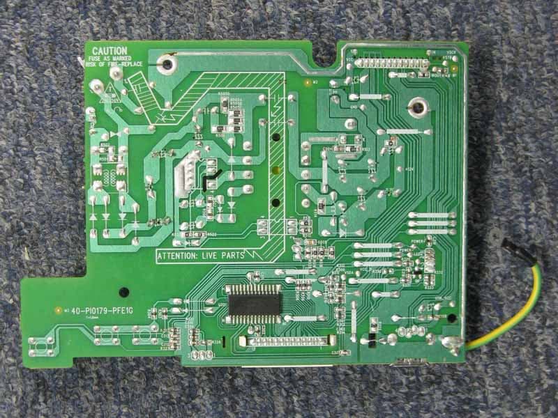
Click to zoom
Application Details
- Equipment Class
- DTS - Digital Transmission System
- Date of Grant
- Dec 27, 2011
- Application Purpose
- Original Equipment
- Date of Application
- Dec 27, 2011
- Equipment Note
- BLU-RAY DISC PLAYER
- Frequency Range
- 2422.00000000 - 2452.00000000
- Company
- Tonly Technology Co., Ltd.
- Country
- China
Documents & Files
Document Text
Text extracted from the exhibit documents filed with the FCC. Open a document above to read the original.
Users Manual
VQT3V18 Owner’s Manual Blu-ray Disc TM Player Model No. DMP-BD87 DMP-BD77 Dear customer Thank you for purchasing this product. For optimum performance and safety, please read these instructions carefully. Please keep this manual for future reference. If you have any questions contact U.S.A. and Puerto Rico : 1-800-211-PANA(7262) Canada : 1-800-561-5505 until 2012/01/5 PPC DMP-BD87_77_VQT3V18_eng.book 1 ページ 2011年10月24日 月曜日 午後2時45分 2 VQT3V18 Getting started IMPORTANT SAFETY INSTRUCTIONS Read these operating instructions carefully before using the unit. Follow the safety instructions on the unit and the applicable safety instructions listed below. Keep these operating instructions handy for future reference. 1 Read these instructions. 2 Keep these instructions. 3 Heed all warnings. 4 Follow all instructions. 5 Do not use this apparatus near water. 6 Clean only with dry cloth. 7 Do not block any ventilation openings. Install in accordance with the manufacturer’s instructions. 8 Do not install near any heat sources such as radiators, heat registers, stoves, or other apparatus (including amplifiers) that produce heat. 9 Do not defeat the safety purpose of the polarized or grounding-type plug. A polarized plug has two blades with one wider than the other. A grounding-type plug has two blades and a third grounding prong. The wide blade or the third prong are provided for your safety. If the provided plug does not fit into your outlet, consult an electrician for replacement of the obsolete outlet. 10 Protect the power cord from being walked on or pinched particularly at plugs, convenience receptacles, and the point where they exit from the apparatus. 11 Only use attachments/accessories specified by the manufacturer. 12 Use only with the cart, stand, tripod, bracket, or table specified by the manufacturer, or sold with the apparatus. When a cart is used, use caution when moving the cart/apparatus combination to avoid injury from tip-over. 13 Unplug this apparatus during lightning storms or when unused for long periods of time. 14 Refer all servicing to qualified service personnel. Servicing is required when the apparatus has been damaged in any way, such as power-supply cord or plug is damaged, liquid has been spilled or objects have fallen into the apparatus, the apparatus has been exposed to rain or moisture, does not operate normally, or has been dropped. (Inside of product) The lightning flash with arrowhead symbol, within an equilateral triangle, is intended to alert the user to the presence of uninsulated “dangerous voltage” within the product’s enclosure that may be of sufficient magnitude to constitute a risk of electric shock to persons. CAUTION CAUTION :TO REDUCE THE RISK OF ELECTRIC SHOCK, DO NOT REMOVE SCREWS. NO USER-SERVICEABLE PARTS INSIDE. REFER SERVICING TO QUALIFIED SERVICE PERSONNEL. The exclamation point within an equilateral triangle is intended to alert the user to the presence of important operating and maintenance (servicing) instructions in the literature accompanying the appliance. RISK OF ELECTRIC SHOCK DO NOT OPEN THE FOLLOWING APPLIES ONLY IN THE U.S.A. FCC Note: This equipment has been tested and found to comply with the limits for a Class B digital device, pursuant to Part 15 of the FCC Rules. These limits are designed to provide reasonable protection against harmful interference in a residential installation. This equipment generates, uses, and can radiate radio frequency energy and, if not installed and used in accordance with the instructions, may cause harmful interference to radio communications. However, there is no guarantee that interference will not occur in a particular installation. If this equipment does cause harmful interference to radio or television reception, which can be determined by turning the equipment off and on, the user is encouraged to try to correct the interference by one or more of the following measures: ≥Reorient or relocate the receiving antenna. ≥Increase the separation between the equipment and receiver. ≥Connect the equipment into an outlet on a circuit different from that to which the receiver is connected. ≥Consult the dealer or an experienced radio/TV technician for help. FCC Caution: To assure continued compliance, follow the attached installation instructions and use only shielded interface cables when connecting to peripheral devices. Any changes or modifications not expressly approved by the party responsible for compliance could void the user’s authority to operate this equipment. This device complies with Part 15 of the FCC Rules. Operation is subject to the following two conditions: (1) This device may not cause harmful interference, and (2) this device must accept any interference received, including interference that may cause undesired operation. Responsible Party: Panasonic Corporation of North America One Panasonic Way, Secaucus, NJ 07094 Support Contact: Panasonic Consumer Electronics Company Telephone No.: 1-800-211-PANA (7262) DMP-BD87_77_VQT3V18_eng.book 2 ページ 2011年10月24日 月曜日 午後2時45分 3 VQT3V18 Unit To reduce the risk of fire, electric shock or product damage, ≥Install this unit so that the power cord can be unplugged from the socket outlet immediately if any problem occurs. ≥Do not expose this unit to rain, moisture, dripping or splashing. ≥Do not place objects filled with liquids, such as vases, on this unit. ≥Use only the recommended accessories. ≥Do not remove covers. ≥Do not repair this unit by yourself. Refer servicing to qualified service personnel. Unit ≥This unit utilizes a laser. Use of controls or adjustments or performance of procedures other than those specified herein may result in hazardous radiation exposure. ≥Do not place sources of naked flames, such as lighted candles, on this unit. Placement To reduce the risk of fire, electric shock or product damage, ≥Do not install or place this unit in a bookcase, built-in cabinet or in another confined space. Ensure this unit is well ventilated. ≥Do not obs…
Text truncated - open the document above for the full version.
Users Manual
21 VQT3V18 Settings Option menu Optional playback operations and settings are available from this menu. Available options differ depending on the playing contents and the condition of the unit. : Settings of the items with this indication are saved by the respective users registered in the Home menu. Please refer to page 15 for details about user registration and switching. 1Press [OPTION]. e.g., BD-Video 2Select an item and change the settings according to the indications. To exit the screen Press [OPTION]. Regarding Language : (>31) Soundtrack Show or change the soundtrack. Audio channel Select the audio channel number. (>16, “Changing audio”) Subtitles Turn the subtitle on/off, and change the language depending on the media. Subtitle Settings Make the subtitle settings. Angle Select the number of the angle. Repeat Play (Only when the elapsed time is being displayed on the unit’s display.) Select the item which you want to repeat. The items displayed differ depending on the type of media. Select “Off” to cancel. Random Select whether or not to play random. Start Slideshow Start the slideshow. Status Show the still picture properties. Rotate Right Rotate Left Rotate the still picture. Wallpaper Set the still picture to the wallpaper of HOME screen. (>14) Icon Set the still picture to the icon of HOME menu. (>15) Operation Menu Menu Top Menu Control Panel Status Repeat Play Angle Subtitle Settings Soundtrack Off 1 1 ENG Digital 3/2. 1ch Operation Menu Playback DMP-BD87_77_VQT3V18_eng.book 21 ページ 2011年10月24日 月曜日 午後2時45分 22 VQT3V18 Video The recording method of original video appears. Primary Video The recording method of original video appears. Secondary Video Settings Top Menu Display Top Menu. Pop-up Menu Display Pop-up Menu. Menu Display Menu. Picture Mode Select the picture quality mode during play. ≥If you select “User”, you can make settings in “Picture Adjustment”. Picture Adjustment Specific picuture quality settings can be performed. Progressive Select the method of conversion for progressive output to suit the type of material being played. ≥When the content is distorted change the settings from “Auto” to “Video”. Reset to Default Picture Settings Return video settings to the factory preset. Video Select on/off of images. The recording method of original video appears. Soundtrack Select on/off of audio and the language. Picture Settings DMP-BD87_77_VQT3V18_eng.book 22 ページ 2011年10月24日 月曜日 午後2時45分 23 VQT3V18 Setup menu Change the unit’s settings if necessary. The settings remain intact even if you switch the unit to standby. : Settings of the items with this indication are saved by the respective users registered in the Home menu. Please refer to page 15 for details about user registration and switching. 1Press [SETUP]. 2Select an item and change the settings according to the indications. To exit the screen Press [SETUP]. Picture Mode (>22) Picture Adjustment (>22) HDMI Output HDMI Resolution The items supported by the connected devices are indicated on the screen as “ ¢”. When any item without “ ¢” is selected, the images may be distorted. ≥If “Auto” is selected, automatically selects the output resolution best suited to the connected television. ≥To enjoy high-definition video up-converted to 1080p, you need to connect the unit directly to 1080p compatible HDTV (High Definition Television). If this unit is connected to an HDTV through other equipment, it must also be 1080p compatible. 24p Output When this unit is connected to a TV supporting 1080/24p output using an HDMI cable, movies and other material recorded at 24p are output at 24p. ≥When playing DVD-Video, set to “On”. ≥When BD-Video images other than 24p are played, images are output at 60p. ≥24p : A progressive image recorded at a rate of 24 frames per second (motion-picture film). Many BD-Video movie contents are recorded in 24 frames/second in accordance with the film materials. Deep Color Output This setting is for selecting whether to use Deep Color output when a television that supports Deep Color is connected. Contents Type Flag Depending on the playback content, the TV will output adjusting to the optimal method when a TV that supports this function is connected. Black Level Control Select lighter or darker for adjusting the black level control to the desired setting for picture enhancement. Digital Audio Output Press [OK] to show the following settings: Dolby D/Dolby D +/Dolby TrueHD DTS/DTS-HD Select the audio signal to output. ≥Select “PCM”, when the connected equipment cannot decode the respective audio format. This unit decodes the audio format and transmits to the connected equipment. ≥Not making the proper settings may result in noise. BD-Video Secondary Audio Select whether to mix or not mix the primary audio and secondary audio (including the button click sound). (>17) If “Off” is selected, the unit outputs the primary audio only. Picture Settings OK RETURN Player Settings System Settings Ratings Network Language 3D Settings Audio Settings Picture Settings Black Level Control Seamless Play Still Mode (paused video) HDMI Connection Super Resolution Detail Clarity Chroma Process Picture Adjustment Picture Mode Lighter Off Auto 1 Off Off Normal Audio Settings Settings DMP-BD87_77_VQT3V18_eng.book 23 ページ 2011年10月24日 月曜日 午後2時45分 24 VQT3V18 HDMI Audio Output This setting selects whether or not to output audio from HDMI. Downmix Select the downmix system of multi-channel to 2-channel sound. ≥Select “Surround encoded”, when the connected equipment supports the virtual surround function. ≥There is no effect on “Bitstream” via HDMI AV OUT and DIGITAL AUDIO OUT. ≥The audio will be output in “Stereo” in the following cases: – AVCHD playback – Playback of secondary audio (including the button click sound). Audio Language Choose the language for audio. ≥If “Original” is selected, the original language of each disc will be selected. ≥Enter a code (>31) with the number buttons when you select “Other ¢¢¢¢”. Subtitle Langu…
Text truncated - open the document above for the full version.
ID Label/Location Info
67-BD77B1-1E0B1 Main label area 67-BD77B1-1E0B1 BD 87 P silkscreen:Black Label
Internal Photos
R AUDIX Technology (Shenzhen) Co., Ltd. IC:9976A-DMPBD87 page Audix Technology (Shenzhen) Co., ltd. Report No. ACS-I11100 15-4 Figure 7 General Appearance of the EUT Figure 8 Inside of the EUT R AUDIX Technology (Shenzhen) Co., Ltd. IC:9976A-DMPBD87 page Audix Technology (Shenzhen) Co., ltd. Report No. ACS-I11100 15-5 Figure 9 Inside of the EUT Figure 10 Inside of the EUT R AUDIX Technology (Shenzhen) Co., Ltd. IC:9976A-DMPBD87 page Audix Technology (Shenzhen) Co., ltd. Report No. ACS-I11100 15-6 Figure 11 Inside of the EUT Figure 12 Component Side of the PCB R AUDIX Technology (Shenzhen) Co., Ltd. IC:9976A-DMPBD87 page Audix Technology (Shenzhen) Co., ltd. Report No. ACS-I11100 15-7 Figure 13 Component Side of the PCB Figure 14 Component Side of the PCB R AUDIX Technology (Shenzhen) Co., Ltd. IC:9976A-DMPBD87 page Audix Technology (Shenzhen) Co., ltd. Report No. ACS-I11100 15-8 Figure 15 Component Side of the PCB Figure 16 Component Side of the PCB R AUDIX Technology (Shenzhen) Co., Ltd. IC:9976A-DMPBD87 page Audix Technology (Shenzhen) Co., ltd. Report No. ACS-I11100 15-9 Figure 17 Component Side of the PCB Figure 18 Component Side of the PCB R AUDIX Technology (Shenzhen) Co., Ltd. IC:9976A-DMPBD87 page Audix Technology (Shenzhen) Co., ltd. Report No. ACS-I11100 15-10 Figure 19 Component Side of the PCB Figure 20 Component Side of the PCB R AUDIX Technology (Shenzhen) Co., Ltd. IC:9976A-DMPBD87 page Audix Technology (Shenzhen) Co., ltd. Report No. ACS-I11100 15-11 Figure 21 Component Side of the PCB Figure 22 Remote Controller
RF Exposure Info
R AUDIX Technology (Shenzhen) Co., Ltd. FCC ID: ZVABDDMPBD87 Page 11-1 Audix Technology (Shenzhen) Co., Ltd. Report No. ACS-F11284 11. MPE ESTIMATION 11.1.Limit for General Population/ Uncontrolled Exposures Frequency Power density (mW/ cm 2 ) Averaging time(minutes) 300MHz----1.5GHz F/1500 30 1.5GHz---100GHz 1.0 30 Frequency(MHz) Power density (mW/ cm 2 ) Averaging time(minutes) 2412 1 30 2437 1 30 2462 1 30 Note: F= Frequency in MHz 11.2.Estimation Result EUT: BLU-RAY DISC PLAYER M/N: DMP-BD87 Test date: 2011-12-12 Pressure: 100.6 kpa Humidity: 47.9% Tested by: Leo-Li Test site: RF Site Temperature:25.6°C Cable loss: 1 dB Attenuator loss: 20 dB Antenna Gain: dBi Test Mode CH Frequency (MHz) Peak Output Power (dBm) Output Power (mW) Antenna Gain (dBi) Antenna Gain (Linear) MPE 11b CH1 2412 17.34 54.20 1.5 1.41 0.0152 CH6 2437 16.70 46.77 1.5 1.41 0.0132 CH11 2462 16.05 40.27 1.5 1.41 0.0113 11g CH1 2412 19.44 87.90 1.5 1.41 0.0247 CH6 2437 19.16 82.41 1.5 1.41 0.0232 CH11 2462 18.34 68.23 1.5 1.41 0.0192 11n HT20 CH1 2412 20.12 102.80 1.5 1.41 0.0289 CH6 2437 19.40 87.10 1.5 1.41 0.0245 CH11 2462 18.29 67.45 1.5 1.41 0.0190 11n HT40 CH1 2422 16.98 49.89 1.5 1.41 0.0140 CH4 2437 16.33 42.95 1.5 1.41 0.0121 CH7 2452 15.98 39.63 1.5 1.41 0.0111 Note:The estimate distance is 20cm
Test Report
R AUDIX Technology (Shenzhen) Co., Ltd. FCC ID: ZVABDDMPBD87 Audix Technology (Shenzhen) Co., Ltd. Report No. ACS-F11284 ` FCC PART 15C TEST REPORT FOR CERTIFICATION On Behalf of TCL Technoly Electronics (Huizhou) Co., Ltd. BLU-RAY DISC PLAYER Brand Name Model Number Panasonic DMP-BD87 FCC ID: ZVABDDMPBD87 Prepared for : TCL Technoly Electronics (Huizhou) Co., Ltd. Section 19, Zhongkai High-tech Development Zone,Huizhou City,Guangdong Province, China 516006 Prepared By : Audix Technology (Shenzhen) Co., Ltd. No. 6, Ke Feng Rd., 52 Block, Shenzhen Science & Industrial Park, Nantou, Shenzhen, Guangdong, China Tel: (0755) 26639496 Report Number : ACS-F11284 Date of Test : Dec.08~15, 2011 Date of Report : Dec.22, 2011 R AUDIX Technology (Shenzhen) Co., Ltd. FCC ID: ZVABDDMPBD87 Audix Technology (Shenzhen) Co., Ltd. Report No. ACS-F11284 TABLE OF CONTENTS Description Page 1. SUMMARY OF STANDARDS AND RESULTS ...................................................... 1-1 1.1. Description of Standards and Results ............................................................................... 1-1 2. GENERAL INFORMATION ...................................................................................... 2-1 2.1. Description of Device (EUT) ............................................................................................ 2-1 2.2. Test information ................................................................................................................ 2-2 2.3. Tested Supporting System Details .................................................................................... 2-3 2.4. Block diagram of connection between the EUT and simulators ....................................... 2-3 2.5. Test Facility ....................................................................................................................... 2-4 2.6. Measurement Uncertainty (95% confidence levels, k=2) ................................................. 2-4 3. POWER LINE CONDUCTED EMISSION TEST .................................................... 3-1 3.1. Test Equipments ................................................................................................................ 3-1 3.2. Block Diagram of Test Setup ............................................................................................ 3-1 3.3. Power Line Conducted Emission Test Limits ................................................................... 3-1 3.4. Configuration of EUT on Test .......................................................................................... 3-1 3.5. Operating Condition of EUT ............................................................................................. 3-2 3.6. Test Procedure ................................................................................................................... 3-2 3.7. Power Line Conducted Emission Test Results ................................................................. 3-2 4. RADIATED EMISSION TEST ................................................................................... 4-1 4.1. Test Equipment ................................................................................................................. 4-1 4.2. Block Diagram of Test Setup ............................................................................................ 4-1 4.3. Radiated Emission Limit ................................................................................................... 4-2 4.4. EUT Configuration on Test ............................................................................................... 4-3 4.5. Operating Condition of EUT ............................................................................................. 4-3 4.6. Test Procedure ................................................................................................................... 4-3 4.7. Radiated Emission Test Results ........................................................................................ 4-4 5. CONDUCTED SPURIOUS EMISSIONS ................................................................ 5-78 5.1. Test Equipment ............................................................................................................... 5-78 5.2. Limit ................................................................................................................................ 5-78 5.3. Test Procedure ................................................................................................................. 5-78 5.4. Test result ........................................................................................................................ 5-78 6. BAND EDGE COMPLIANCE TEST ......................................................................... 6-1 6.1. Test Equipment ................................................................................................................. 6-1 6.2. Limit .................................................................................................................................. 6-1 6.3. Test Produce ...................................................................................................................... 6-1 6.4. Test Results ....................................................................................................................... 6-1 7. 6dB Bandwidth Test ................................................................................................... 7-34 7.1. Test Equipment ............................................................................................................... 7-34 7.2. Limit ................................................................................................................................ 7-34 7.3. Test Procedure ................................................................................................................. 7-34 7.4. Test Results ............................................................................…
Text truncated - open the document above for the full version.
Test Setup Photos
R AUDIX Technology (Shenzhen) Co., Ltd. IC:9976A-DMPBD87 page Audix Technology (Shenzhen) Co., ltd. Report No. ACS-I11100 14-1 14. PHOTOGRAPH OF TEST 14.1.Photos of Power Line Conducted Emission Test R AUDIX Technology (Shenzhen) Co., Ltd. IC:9976A-DMPBD87 page Audix Technology (Shenzhen) Co., ltd. Report No. ACS-I11100 14-2 14.2.Photos of Radiated Emission Test R AUDIX Technology (Shenzhen) Co., Ltd. IC:9976A-DMPBD87 page Audix Technology (Shenzhen) Co., ltd. Report No. ACS-I11100 14-3 (Above 1000MHz)
Contact Information
Applicant
Hao Wang(Compliance Director)
Technical Contact
AUDIX Technology (Shenzhen) Co., Ltd.Lu Ken
52 Block Shenzhen Science&Industry · Shenzhen · China
Test Firm
Audix Technology (Shenzhen) Co.Smart Tsai
Technical Specifications
| # | Rule Parts | Frequency Range | Power Output |
|---|---|---|---|
| 2 | 15C | 2.42 GHz - 2.45 GHz | 49.90 mW |
Other Applications from Tonly Technology Co., Ltd.
ZVAOH000037
Apr 28, 2026BDX Character Robot
Equipment Class
DSS - Part 15 Spread Spectrum TransmitterZVAOH000038
Apr 28, 2026LoRa Backpack
Equipment Class
DSS - Part 15 Spread Spectrum TransmitterZVAYY7870E
Apr 01, 2026WIRELESS SPEAKER
Equipment Class
DSS - Part 15 Spread Spectrum TransmitterZVAYY7871E
Mar 31, 2026WIRELESS SPEAKER
Equipment Class
DTS - Digital Transmission System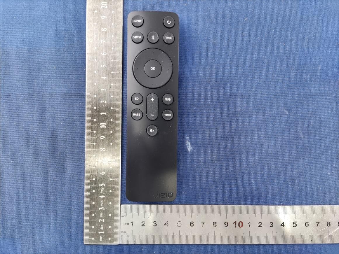
ZVASB000027
Nov 06, 20232.1 Soundbar System
Equipment Class
DSS - Part 15 Spread Spectrum Transmitter