ZVASB000016HOME THEATRE SYSTEM
Tonly Technology Co., Ltd.
Click to zoom
Application Details
- Equipment Class
- DTS - Digital Transmission System
- Date of Grant
- Nov 04, 2014
- Application Purpose
- Original Equipment
- Date of Application
- Nov 03, 2014
- Equipment Note
- HOME THEATRE SYSTEM
- Frequency Range
- 2402.00000000 - 2480.00000000
- Company
- Tonly Technology Co., Ltd.
- Country
- China
Documents & Files
Document Text
Text extracted from the exhibit documents filed with the FCC. Open a document above to read the original.
Users Manual
F:\HT-XZ1-11_UC\4559030111\4559030111HTXT100UC\01US- HTXT100UC\010COV.fm masterpage: Right HT-XT100 4-559-030-11(1) 4-559-030-11(1) HT-XT100 Operating Instructions US Guide de référence FR Manual de instrucciones ES Home Theatre System 010COV.fm Page 1 Monday, August 18, 2014 3:51 PM 2 US HT-XT100 4-559-030-11(1) F:\HT-XZ1-11_UC\4559030111\4559030111HTXT100UC\01US- HTXT100UC\020REG.fm masterpage: Left Owner’s Record The model and serial numbers are located on the rear panel of the unit. Record serial numbers in the space provided below. Refer to them whenever you call upon your Sony dealer regarding this product. Model No. HT-XT100 Serial No._____________________________ To reduce the risk of fire or electric shock, do not expose this apparatus to rain or moisture. The unit is not disconnected from the mains as long as it is connected to the AC outlet, even if the unit itself has been turned off. To reduce the risk of fire, do not cover the ventilation opening of the appliance with newspapers, tablecloths, curtains, etc. Do not expose the appliance to naked flame sources (for example, lighted candles). To reduce the risk of fire or electric shock, do not expose this appliance to dripping or splashing, and do not place objects filled with liquids, such as vases, on the appliance. As the main plug is used to disconnect the unit from the mains, connect the unit to an easily accessible AC outlet. Should you notice an abnormality in the unit, disconnect the main plug from the AC outlet immediately. Do not install the appliance in a confined space, such as a bookcase or built-in cabinet. Do not expose batteries or appliances with battery-installed to excessive heat, such as sunshine and fire. Indoor use only. For the customers in the U.S.A. This symbol is intended to alert the user to the presence of uninsulated “dangerous voltage” within the product’s enclosure that may be of sufficient magnitude to constitute a risk of electric shock to persons. This symbol is intended to alert the user to the presence of important operating and maintenance (servicing) instructions in the literature accompanying the appliance. Important Safety Instructions 1) Read these instructions. 2) Keep these instructions. 3) Heed all warnings. 4) Follow all instructions. 5) Do not use this apparatus near water. 6) Clean only with dry cloth. 7) Do not block any ventilation openings. Install in accordance with the manufacturer’s instructions. 8) Do not install near any heat sources such as radiators, heat registers, stoves, or other apparatus (including amplifiers) that produce heat. 9) Do not defeat the safety purpose of the polarized or grounding-type plug. A polarized plug has two blades with one wider than the other. A grounding type plug has two blades and a third grounding prong. The wide blade or the third prong are provided for your safety. If the provided plug does not fit into your outlet, consult an electrician for replacement of the obsolete outlet. WARNING 010COV.book Page 2 Monday, August 18, 2014 3:50 PM H-1001-0001 A-1015-0001 A-1021-0001 A-1022-0002 A-1016-0005 A-1020-0001 A-1018-0001 A-1025-0002 A-1017-0001 A-1110-0001 F:\HT-XZ1-11_UC\4559030111\4559030111HTXT100UC\01US- HTXT100UC\020REG.fm masterpage: Right 3 US HT-XT100 4-559-030-11(1) 10) Protect the power cord from being walked on or pinched particularly at plugs, convenience receptacles, and the point where they exit from the apparatus. 11) Only use attachments/accessories specified by the manufacturer. 12) Use only with the cart, stand, tripod, bracket, or table specified by the manufacturer, or sold with the apparatus. When a cart is used, use caution when moving the cart/ apparatus combination to avoid injury from tip-over. 13) Unplug this apparatus during lightning storms or when unused for long periods of time. 14) Refer all servicing to qualified service personnel. Servicing is required when the apparatus has been damaged in any way, such as power- supply cord or plug is damaged, liquid has been spilled or objects have fallen into the apparatus, the apparatus has been exposed to rain or moisture, does not operate normally, or has been dropped. The following FCC statement applies only to the version of this model manufactured for sale in the U.S.A. Other versions may not comply with FCC technical regulations. NOTE: This equipment has been tested and found to comply with the limits for a Class B digital device, pursuant to Part 15 of the FCC Rules. These limits are designed to provide reasonable protection against harmful interference in a residential installation. This equipment generates, uses, and can radiate radio frequency energy and, if not installed and used in accordance with the instructions, may cause harmful interference to radio communications. However, there is no guarantee that interference will not occur in a particular installation. If this equipment does cause harmful interference to radio or television reception, which can be determined by turning the equipment off and on, the user is encouraged to try to correct the interference by one or more of the following measures: – Reorient or relocate the receiving antenna (aerial). – Increase the separation between the equipment and receiver. – Connect the equipment into an outlet on a circuit different from that to which the receiver is connected. – Consult the dealer or an experienced radio/TV technician for help. Properly shielded and grounded cables and connectors must be used for connection to host computers and/or peripherals in order to meet FCC emission limits. CAUTION You are cautioned that any changes or modifications not expressly approved in this manual could void your authority to operate this equipment. This equipment must not be co-located or operated in conjunction with any other antenna or transmitter. This equipment complies with FCC radiation exposure limits set forth for an uncontrolled environment and meets the FCC radio frequency (RF) Exposure Guidelines. This e…
Text truncated - open the document above for the full version.
Cover Letter(s)
TCL TECHNOLY ELECTRONICS (HUI ZHOU) CO.,LTD Section 37 Zhongkai High-tech Development Zone, Huizhou City, Guangdong Province, 516006 P.R. China TEL: 86 752-2638000 FAX: 86 752-2606641 Website: www.tcl.com AGENCY AUTHORIZATION LETTER FCC ID:ZVASB000016 Date: 2014-9-18 To whom it may concern: We, the undersigned, hereby authorize Audix Technology (ShenZhen) Co.,Ltd to act on our behalf, as our agent, in the following matters related to the FCC approval of our products: report submittal, related correspondence, the signing of all documents relating to these matters, and any other lawful activity necessary to obtain such certification. Any act carried out by Audix within the scope of this authorization shall have the same effects as our own. This authorization shall expire 6 months form original date. If you have any Questions regarding the authorization, please don’t hesitate to contact us. Thank you. Sincerely, Name of authorized signer):Weirun Peng Title of authorized signer: Chief Approbation Engineer Company Name: TCL TECHNOLY ELECTRONICS (HUIZHOU) CO., LTD Section 37,Zhongkai High-Tech Development Zone, Huizhou City, Guangdong Province, P.R.China Tel: 86-752-2606710 Fax: ? Web site: www.tcl.com E-mail: [email protected]
Cover Letter(s)
TCL TECHNOLY ELECTRONICS (HUI ZHOU) CO.,LTD Section 37 Zhongkai High-tech Development Zone, Huizhou City, Guangdong Province, 516006 P.R. China TEL: 86 752-2638000 FAX: 86 752-2606641 Website: www.tcl.com Date: 2014-9-8 Federal Communications Commission Authorization and Evaluation Division FCC ID: ZVASB000016 Confidentiality Request Pursuant to Sections 0.457 and 0.459 of the Commission’s Rules, the Applicant hereby requests confidential treatment of information accompanying this application as outlined below: 1. Block diagram 2. Schematics 3. Operation Description The above materials contain trade secrets and proprietary information not customarily released to the public. The public disclosure of these matters might to harmful to the applicant and provide unjustified benefits to its competitors. The applicant understands that pursuant to Rule 0.457, disclosure of this application and all accompanying documentation will not be made before the date of the grant for this application. Sincerely, Name of authorized signer): Weirun Peng Title of authorized signer: Approbation Engineer Company Name: TCL Technoly Electronics(Huizhou) Co.,Ltd. Tel: 86-752-2606710 Fax:86-752 3270728 Web site:www.tcl.com E-mail: [email protected]
External Photos
R AUDIX Technology (Shenzhen) Co., Ltd. FCC ID:ZVASB000016 page Audix Technology (Shenzhen) Co., Ltd. Report No. ACS-F14308 14-1 14. PHOTOGRAPH OF EUT Figure 1 General Appearance of the EUT Figure 2 General Appearance of the EUT R AUDIX Technology (Shenzhen) Co., Ltd. FCC ID:ZVASB000016 page Audix Technology (Shenzhen) Co., Ltd. Report No. ACS-F14308 14-2 Figure 3 General Appearance of the EUT Figure 4 General Appearance of the EUT R AUDIX Technology (Shenzhen) Co., Ltd. FCC ID:ZVASB000016 page Audix Technology (Shenzhen) Co., Ltd. Report No. ACS-F14308 14-3 Figure 5 General Appearance of the EUT Figure 6 I/O Port of the EUT
ID Label/Location Info
MATERIAL COMPOSITION FIGURE Polyester Film(t0.016) Laminate Printing surface Polyester Film(TLW50/50#PET) Acrylic-base pressure-sensitive adhesive Silicone-impregnated release paper PETP + PSA (t=0.119) <CAUTION> 3) This drawing is for printing contents. Letterring font, size and position are depending on the print data. この図面は印刷表示内容を示す。書体、文字大きさ、配置寸法など詳細は印刷データに拠ること。 1) Purchase recycled resins and wire rods only from the business partners that Sony approves as Green Partners. 再生樹脂・被覆電線はグリーンパートナー認定取引先から調達すること。 2) This part should not contain any substances which are specified in SS-00259-01. この部品には SS-00259-01 に指定する物質を含んだ材料は、使用してはならない。 EC-F ‘14. V&S 2014.8.11 川 畑 SOUND2,HA4 V&S 2014.8.11 川 畑 SOUND2,HA4 Location
Internal Photos
R AUDIX Technology (Shenzhen) Co., Ltd. FCC ID:ZVASB000016 page Audix Technology (Shenzhen) Co., Ltd. Report No. ACS-F14308 14-4 Figure 7 Inside of the EUT Figure 8 Inside of the EUT R AUDIX Technology (Shenzhen) Co., Ltd. FCC ID:ZVASB000016 page Audix Technology (Shenzhen) Co., Ltd. Report No. ACS-F14308 14-5 Figure 9 Inside of the EUT Figure 10 Inside of the EUT R AUDIX Technology (Shenzhen) Co., Ltd. FCC ID:ZVASB000016 page Audix Technology (Shenzhen) Co., Ltd. Report No. ACS-F14308 14-6 Figure 11 Frontside of the Main Board Figure 12 Backside of the Main Board R AUDIX Technology (Shenzhen) Co., Ltd. FCC ID:ZVASB000016 page Audix Technology (Shenzhen) Co., Ltd. Report No. ACS-F14308 14-7 Figure 13 Frontside of the Power Board Figure 14 Backside of the Power Board R AUDIX Technology (Shenzhen) Co., Ltd. FCC ID:ZVASB000016 page Audix Technology (Shenzhen) Co., Ltd. Report No. ACS-F14308 14-8 Figure 15 Frontside of the PCB Board Figure 16 Backside of the PCB Board R AUDIX Technology (Shenzhen) Co., Ltd. FCC ID:ZVASB000016 page Audix Technology (Shenzhen) Co., Ltd. Report No. ACS-F14308 14-9 Figure 17 Frontside of the PCB Board Figure 18 Backside of the PCB Board R AUDIX Technology (Shenzhen) Co., Ltd. FCC ID:ZVASB000016 page Audix Technology (Shenzhen) Co., Ltd. Report No. ACS-F14308 14-10 Figure 19 Frontside of the PCB Board Figure 20 Backside of the PCB Board R AUDIX Technology (Shenzhen) Co., Ltd. FCC ID:ZVASB000016 page Audix Technology (Shenzhen) Co., Ltd. Report No. ACS-F14308 14-11 Figure 21 Frontside of the PCB Board Figure 22 Remote Commander R AUDIX Technology (Shenzhen) Co., Ltd. FCC ID:ZVASB000016 page Audix Technology (Shenzhen) Co., Ltd. Report No. ACS-F14308 14-12 Figure 23 Remote Commander Figure 24 Optical Cable
Test Report
R AUDIX Technology (Shenzhen) Co., Ltd. FCC ID:ZVASB000016 Audix Technology (Shenzhen) Co., Ltd. Report No. ACS-F14309 FCC PART 15C TEST REPORT FOR CERTIFICATION On Behalf of TCL Technoly Electronics (Huizhou) Co., Ltd. HOME THEATRE SYSTEM Brand NameModel No. Sony HT-XT100 FCC ID: ZVASB000016 Prepared for : TCL Technoly Electronics (Huizhou) Co., Ltd. Secion 37, Zhongkai High-tech Development Zone, Huizhou City, Guangdong Province, P.R. China. Prepared By : Audix Technology (Shenzhen) Co., Ltd. No. 6, Ke Feng Rd., 52 Block, Shenzhen Science & Industrial Park, Nantou, Shenzhen, Guangdong, China Tel: (0755) 26639496 Report Number : ACS-F14309 Date of Test : Sep.11~22, 2014 Date of Report : Oct.23, 2014 R AUDIX Technology (Shenzhen) Co., Ltd. FCC ID:ZVASB000016 Audix Technology (Shenzhen) Co., Ltd. Report No. ACS-F14309 TABLE OF CONTENTS Description Page 1. SUMMARY OF STANDARDS AND RESULTS ......................................................... 1-1 1.1. Description of Standards and Results .................................................................................. 1-1 2. GENERAL INFORMATION ......................................................................................... 2-1 2.1. Description of Device (EUT) ............................................................................................... 2-1 2.2. Tested Supporting System Details ....................................................................................... 2-2 2.3. Block Diagram of connection between EUT and simulators ............................................... 2-2 2.4. Test information ................................................................................................................... 2-2 2.5. Test Facility.......................................................................................................................... 2-3 2.6. Measurement Uncertainty (95% confidence levels, k=2) .................................................... 2-3 3. POWER LINE CONDUCTED EMISSION MEASUREMENT ................................. 3-1 3.1. Test Equipment .................................................................................................................... 3-1 3.2. Block Diagram of Test Setup ............................................................................................... 3-1 3.3. Power Line Conducted Emission Test Limits...................................................................... 3-1 3.4. Configuration of EUT on Test ............................................................................................. 3-2 3.5. Operating Condition of EUT................................................................................................ 3-2 3.6. Test Procedure...................................................................................................................... 3-2 3.7. Conducted Emission at Mains Terminals Test Results ........................................................ 3-2 4. RADIATED EMISSION MEASUREMENT ................................................................ 4-1 4.1. Test Equipment .................................................................................................................... 4-1 4.2. Block Diagram of Test Setup ............................................................................................... 4-2 4.3. Radiated Emission Limit Standard: FCC 15.209 ................................................................. 4-3 4.4. EUT Configuration on Test.................................................................................................. 4-3 4.5. Operating Condition of EUT................................................................................................ 4-3 4.6. Test Procedure...................................................................................................................... 4-4 4.7. Radiated Emission Test Results ........................................................................................... 4-4 5. CONDUCTED SPURIOUS EMISSIONS ..................................................................... 5-1 5.1. Test Equipment .................................................................................................................... 5-1 5.2. Limit..................................................................................................................................... 5-1 5.3. Test Procedure...................................................................................................................... 5-1 5.4. Test result ............................................................................................................................. 5-1 6. 6dB BANDWIDTH TEST ............................................................................................... 6-1 6.1. Test Equipment .................................................................................................................... 6-1 6.2. Limit..................................................................................................................................... 6-1 6.3. Test Procedure...................................................................................................................... 6-1 6.4. Test Results .......................................................................................................................... 6-1 7. MAXIMUM PEAK OUTPUT POWER TEST ............................................................. 7-1 7.1. Test Equipment .................................................................................................................... 7-1 7.2. Limit..................................................................................................................................... 7-1 7.3. Test Procedure...................................................................................................................... 7-1 7.4. Test Results ................................................…
Text truncated - open the document above for the full version.
Test Report
R AUDIX Technology (Shenzhen) Co., Ltd. FCC ID:ZVASB000016 page Audix Technology (Shenzhen) Co., Ltd. Report No. ACS-F14309 4-19 R AUDIX Technology (Shenzhen) Co., Ltd. FCC ID:ZVASB000016 page Audix Technology (Shenzhen) Co., Ltd. Report No. ACS-F14309 4-20 Frequency (MHz) Peak level (dBuv/m) Duty cycle factor (dB) AV level (dBuv/m) Limit(dBuv/m) Conclusion 7440 58.82 -43.742 15.078 54 Pass R AUDIX Technology (Shenzhen) Co., Ltd. FCC ID:ZVASB000016 page Audix Technology (Shenzhen) Co., Ltd. Report No. ACS-F14309 5-1 5. CONDUCTED SPURIOUS EMISSIONS 5.1. Test Equipment Item Equipment ManufacturerModel No. Serial No. Last Cal. Cal. Interval 1. Spectrum AnalyzerAgilent E4446A US44300459 Oct.31, 13 1 Year 2. Attenuator Agilent 8491B MY39262165Apr.24,14 1 Year 3. RF Cable HubersuhnerSUCOFLEX10228618/2 Apr.24,14 1 Year 5.2. Limit In any 100kHz bandwidth outside the frequency bands in which the spread spectrum intentional radiator in operating, the radio frequency power that is produced by the intentional radiator shall be at least 20dB below that in the 100kHz bandwidth within the band that contains the highest level of the desired power. 5.3. Test Procedure The transmitter output was connected to a spectrum analyzer, The resolution bandwidth is set to 100 kHz, The video bandwidth is set to 300 kHz and measure all the emissions detected. 5.4. Test result PASS (The testing data was attached in the next pages.) R AUDIX Technology (Shenzhen) Co., Ltd. FCC ID:ZVASB000016 page Audix Technology (Shenzhen) Co., Ltd. Report No. ACS-F14309 5-2 GFSK 2402MHz R AUDIX Technology (Shenzhen) Co., Ltd. FCC ID:ZVASB000016 page Audix Technology (Shenzhen) Co., Ltd. Report No. ACS-F14309 5-3 R AUDIX Technology (Shenzhen) Co., Ltd. FCC ID:ZVASB000016 page Audix Technology (Shenzhen) Co., Ltd. Report No. ACS-F14309 5-4 2440MHz R AUDIX Technology (Shenzhen) Co., Ltd. FCC ID:ZVASB000016 page Audix Technology (Shenzhen) Co., Ltd. Report No. ACS-F14309 5-5 2480MHz R AUDIX Technology (Shenzhen) Co., Ltd. FCC ID:ZVASB000016 page Audix Technology (Shenzhen) Co., Ltd. Report No. ACS-F14309 5-6 R AUDIX Technology (Shenzhen) Co., Ltd. FCC ID:ZVASB000016 page Audix Technology (Shenzhen) Co., Ltd. Report No. ACS-F14309 5-7 R AUDIX Technology (Shenzhen) Co., Ltd. FCC ID:ZVASB000016 page Audix Technology (Shenzhen) Co., Ltd. Report No. ACS-F14309 6-1 6. 6dB BANDWIDTH TEST 6.1. Test Equipment Item Equipment ManufacturerModel No. Serial No. Last Cal. Cal. Interval 1. Spectrum Agilent N9030A MY51380221Oct.31, 13 1Year 2. Attenuator (20dB) Agilent 8491B MY39262165Apr. 28,14 1 Year 3. RF Cable HubersuhnerSUCOFLEX10228620/2 Apr. 28,14 1 Year 6.2. Limit For direct sequence systems, the minimum 6dB bandwidth shall be at least 500kHz 6.3. Test Procedure The transmitter output was connected to a spectrum analyzer, The bandwidth of the fundamental frequency was measured by spectrum analyzer with 100kHz RBW and 300kHz VBW. The 6dB bandwidth is defined as the total spectrum the power of which is higher than peak power minus 6dB. 6.4. Test Results EUT: HOME THEATRE SYSTEM M/N: HT-XT100 Test date: 2014-09-15 Pressure: 101.4±1.0 kpa Humidity: 53.5±1.0% Tested by: Kobe-Huang Test site: RF site Temperature:22.6±1.0°C Test Mode Frequency (MHz) -6dB bandwidth (KHz) Limit (KHz) 2402 694.8 >500 2440 688.4 >500 GFSK 2480 693.8 >500 Conclusion:PASS R AUDIX Technology (Shenzhen) Co., Ltd. FCC ID:ZVASB000016 page Audix Technology (Shenzhen) Co., Ltd. Report No. ACS-F14309 6-2 GFSK Test Frequency: 2402MHz Test Frequency: 2440MHz R AUDIX Technology (Shenzhen) Co., Ltd. FCC ID:ZVASB000016 page Audix Technology (Shenzhen) Co., Ltd. Report No. ACS-F14309 6-3 Test Frequency: 2480MHz R AUDIX Technology (Shenzhen) Co., Ltd. FCC ID:ZVASB000016 page Audix Technology (Shenzhen) Co., Ltd. Report No. ACS-F14309 7-1 7. MAXIMUM PEAK OUTPUT POWER TEST 7.1. Test Equipment Ite m Equipment Manufacturer Model No. Serial No. Last Cal. Cal. Interval 1. Spectrum Agilent N9030A MY51380221Oct.31, 13 1Year 2. Power meter Anritsu ML2487A 6K00002472 Apr. 28,14 1Year 3. Power sensor Anritsu MA2491A 0033005 Apr. 28,14 1Year 4. Attenuator (20dB) Agilent 8491B MY39262165Apr. 28,14 1 Year 5 RF Cable Hubersuhner SUCOFLEX10228610/2 Apr. 28,14 1 Year 7.2. Limit For frequency hopping systems operating in the 2400-2483.5 MHz band employing at least 75 non-overlapping hopping channels, and all frequency hopping systems in the 5725-5850 MHz band: 1 watt. For all other frequency hopping systems in the 2400-2483.5 MHz band: 0.125 watts. 7.3. Test Procedure Connected the EUT’s antenna port to Power Sensor, and use power meter to test peak output power. 7.4. Test Results EUT: HOME THEATRE SYSTEM M/N: HT-XT100 Test date: 2014-09-15 Pressure: 101.6±1.0kpa Humidity: 53.4±1.0% Tested by: Kobe-Huang Test site: RF site Temperature:22.6±1.0°C Test Mode Frequency (MHz) Peak output Power (dBm) Limit (dBm) 2402 7.298 30 2440 8.545 30 GFSK 2480 8.579 30 Conclusion: PASS R AUDIX Technology (Shenzhen) Co., Ltd. FCC ID:ZVASB000016 page Audix Technology (Shenzhen) Co., Ltd. Report No. ACS-F14309 8-1 8. BAND EDGE COMPLIANCE TEST 8.1. Test Equipment Item Equipment ManufacturerModel No. Serial No. Last Cal. Cal. Interval 1. Amp HP 8449B 3008A02495Apr. 28,14 1 Year 2. Horn Antenna ETS 3115 9510-4580 Jun. 06, 14 1 Year 3. HF Cable Hubersuhner Sucoflex104274094/4 Apr. 28,14 1 Year 4. RF Cable Hubersuhner Sucoflex10228610/2 Apr. 28,14 1 Year 8.2. Limit All the lower and upper band-edges emissions appearing within 2310MHz to 2390MHz and 2483.5MHz to 2500MHz restricted frequency bands shall not exceed the limits shown in 15.209, all the other emissions outside operation frequency band 2400MHz to 2483.5MHz shall be at least 20dB below the fundamental emissions, or comply with 15.209 limits. 8.3. Test Produce For upper band emissions that are up to two bandwidths(2MHz) away (2483.5MHz to 2485.5MHz)from the band-edge use below produce: 1. Choose a spectrum analyzer span that encompasses both the peak of the fundamental emis…
Text truncated - open the document above for the full version.
Test Setup Photos
R AUDIX Technology (Shenzhen) Co., Ltd. FCC ID:ZVASB000016 page Audix Technology (Shenzhen) Co., Ltd. Report No. ACS-F14308 13-1 13. HOTOGRAPH OF TEST 13.1.Photos of Power Line Conducted Emission Test R AUDIX Technology (Shenzhen) Co., Ltd. FCC ID:ZVASB000016 page Audix Technology (Shenzhen) Co., Ltd. Report No. ACS-F14308 13-2 13.2.Photos of Radiated Emission Test 30-1000MHz R AUDIX Technology (Shenzhen) Co., Ltd. FCC ID:ZVASB000016 page Audix Technology (Shenzhen) Co., Ltd. Report No. ACS-F14308 13-3 Above 1000MHz
Contact Information
Applicant
Hao Wang(Compliance Director)
Technical Contact
AUDIX Technology (Shenzhen) Co., Ltd.
[email protected]86-755-26639497
52 Block Shenzhen Science&Industry · Shenzhen · China
Non-Technical Contact
AUDIX Technology (Shenzhen) Co., Ltd.
[email protected]86-755-26639497
Test Firm
Audix Technology (Shenzhen) Co.Smart Tsai
Technical Specifications
| # | Rule Parts | Frequency Range | Power Output |
|---|---|---|---|
| 1 | 15C | 2.40 GHz - 2.48 GHz | 7.20 mW |
Other Applications from Tonly Technology Co., Ltd.
ZVAOH000037
Apr 28, 2026BDX Character Robot
Equipment Class
DSS - Part 15 Spread Spectrum TransmitterZVAOH000038
Apr 28, 2026LoRa Backpack
Equipment Class
DSS - Part 15 Spread Spectrum TransmitterZVAYY7870E
Apr 01, 2026WIRELESS SPEAKER
Equipment Class
DSS - Part 15 Spread Spectrum TransmitterZVAYY7871E
Mar 31, 2026WIRELESS SPEAKER
Equipment Class
DTS - Digital Transmission System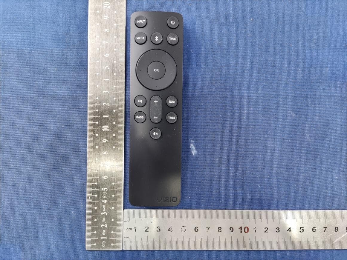
ZVASB000027
Nov 06, 20232.1 Soundbar System
Equipment Class
DSS - Part 15 Spread Spectrum Transmitter