ZVASB000024Sound Bar System
Tonly Technology Co., Ltd.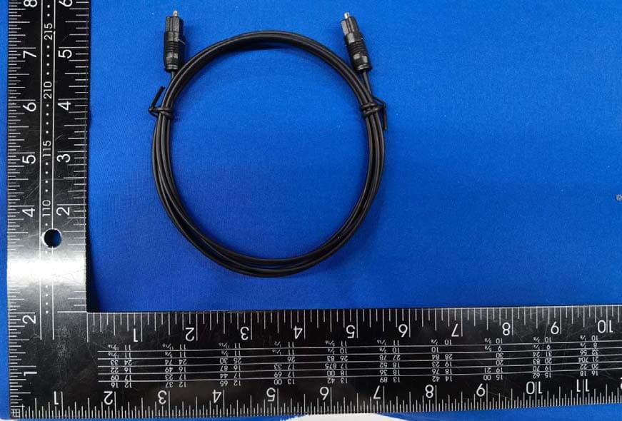
Click to zoom
Application Details
- Equipment Class
- DSS - Part 15 Spread Spectrum Transmitter
- Date of Grant
- May 08, 2021
- Application Purpose
- Original Equipment
- Date of Application
- May 08, 2021
- Equipment Note
- Sound Bar System
- Frequency Range
- 2402.00000000 - 2480.00000000
- Company
- Tonly Technology Co., Ltd.
- Country
- China
Documents & Files
Document Text
Text extracted from the exhibit documents filed with the FCC. Open a document above to read the original.
Users Manual
V-Series ™ 2.0 User Manual Scan to learn more. Model: V20-J8 Please read this guide before using the product. ENG - ii ENG - iii Accessibility Contact VIZIO for accessibility support at: Email: [email protected] Phone: 1-877-698-4746 Binding Arbitration Agreement and Class Action Waiver This purchase is subject to full VIZIO Terms and Conditions, including Binding Arbitration Agreement and Class Action Waiver, which may be viewed at vizio.com/en/terms/terms-of-service. By using this device, you accept those Terms and Conditions. You have the right to opt out of the Binding Arbitration Agreement and Class Action Waiver within 60 calendar days of your purchase. Please refer to the Limited Warranty section of this User Manual or view the full VIZIO Terms and Conditions for opt-out instructions. ENG - iv IMPORTANT SAFETY INSTRUCTIONS Your Unit is designed and manufactured to operate within defined design limits, and misuse may result in electric shock or fire. To prevent your Unit from being damaged, the following rules should be observed for its installation, use, and maintenance. Please read the following safety instructions before operating your Unit. Keep these instructions in a safe place for future reference. • Heed all warnings. • Follow all instructions. • Do not use this Unit near water. • Clean only with a dry cloth. • Do not block any ventilation openings. Install in accordance with the manufacturer’s instructions. • Do not install near any heat sources such as radiators, heat registers, stoves, or other Unit (including amplifiers) that produce heat. • Do not defeat the safety purpose of the polarized or grounding-type plug. A polarized plug has two blades with one wider than the other. A grounding type plug has two blades and a third grounding prong. The wide blade or the third prong are provided for your safety. If the provided plug does not fit into your outlet, consult an electrician for replacement of the obsolete outlet. • Protect the power cord from being walked on or pinched particularly at the ends where the plug is located, near convenience receptacles, or where they exit from the Unit. • Only use attachments/accessories specified by the manufacturer. • Use only with the stand, tripod, or bracket specified by the manufacturer, or sold with the Unit. When a cart is used, use caution when moving the cart/Unit combination to avoid injury from tip-over. • Unplug this Unit during lightning storms or when unused for long periods of time. • Refer all servicing to qualified service personnel. Servicing is required when the Unit has been damaged in any way, such as when the power supply cord or plug is damaged, liquid has been spilled or objects have fallen into the Unit, the Unit has been exposed to rain or moisture, does not operate normally, or has been dropped. • To reduce the risk of electric shock or component damage, switch off the power before connecting other components to your Unit. • Unplug the power cord before cleaning your Unit. A damp cloth is sufficient for cleaning. Do not use a liquid or a spray cleaner on your Unit. Do not use abrasive cleaners. • Always use the accessories recommended by the manufacturer to ensure compatibility. • When moving your Unit from an area of low temperature to an area of high temperature, condensation may form in the housing. Wait before turning on your Unit to avoid causing fire, electric shock, or component damage. • Slots and openings in the back and bottom of the Unit are provided for ventilation. To ensure reliable operation of your Unit and to protect it from overheating, be sure these openings are not blocked or covered. Do not place your Unit in a bookcase or cabinet unless proper ventilation is provided. • Never push any object into the slots and openings on your Unit. Do not place any objects on the top of your Unit. Doing so could short circuit parts causing a fire or electric shock. Never spill liquids on your Unit. • Do not block the subwoofer ports. Allow for 1-2 inches of space around all sides for ventilation. • WARNING: Exposure to loud sounds can damage your hearing causing hearing loss and tinnitus (ringing or buzzing in the ears). With continued exposure to loud noises, ears may become accustomed to the sound level, which may result in permanent damage to hearing without any noticeable discomfort. • When connected to a power outlet, power is always flowing into your Unit. To totally disconnect power, unplug the power cord. • Do not overload power strips and extension cords. Overloading can result in fire or electric shock. • The wall socket should be located near your Unit and be easily accessible. • Keep your Unit away from moisture. Do not expose your Unit to rain or moisture. If water penetrates into your Unit, unplug the power cord and contact your dealer. Continuous use in this case may result in fire or electric shock. ENG - v IMPORTANT SAFETY INSTRUCTIONS • Do not use your Unit if any abnormality occurs. If any smoke or odor becomes apparent, unplug the power cord and contact your dealer immediately. Do not try to repair your Unit yourself. • Avoid using dropped or damaged appliances. If your Unit is dropped and the housing is damaged, the internal components may function abnormally. Unplug the power cord immediately and contact your dealer for repair. Continued use of your Unit may cause fire or electric shock. • Do not install your Unit in an area with heavy dust or high humidity. Operating your Unit in environments with heavy dust or high humidity may cause fire or electric shock. • Ensure that the power cord and any other cables are unplugged before moving your Unit. • When unplugging your Unit, hold the power plug, not the cord. Pulling on the power cord may damage the wires inside the cord and cause fire or electric shock. When your Unit will not be used for an extended period of time, unplug the power cord. • To reduce risk of electric shock, do not touch the connector with wet hands. • Insert …
Text truncated - open the document above for the full version.
Users Manual
Quick Setup Guide More questions? Get customer support help and view the User Manual here: support.vizio.com Unlock the best picture and audio quality with a VIZIO SmartCast® TV. Scan here to shop our V-series ™ TVs: HDMI ARC (to TV) HOME THEATER DISPLAY | QUICK START GUIDE Installation Guide | Models: HDMI (ARC or eARC) • Then use the included HDMI cable to connect to your TV. 2 Why HDMI? Highest Quality Connection. Connect to the HDMI ARC/eARC port on your TV for the best possible sound quality. Get easy setup videos and more. Scan with your phone camera or QR reader. vizio.com/qr/V20-J8 Connect. • Plug in the power cable to power on your sound bar. 1 FAQs Best speaker placement for my sound bar? For the best sound experience, position the sound bar and subwoofer as shown. The sound bar should be close to ear level. If the subwoofer is too boomy or lacking impact, adjust the Subwoofer level with your remote control or try various placements. Can I connect to a Voice Assistant (VA) device? Connect your voice assistant devices (sold separately) to the sound bar for an amplified audio experience that’s always ready to respond. Please see the User Manual for more information. The sound bar will automatically lower the volume while watching a movie or listening to music, when a VA device is connected. OR Bluetooth ConnectionConnect to the AUX VA port How do I adjust sound settings and levels? Using the included remote, you can easily adjust many different sound settings and levels to optimize your listening experience, including EQ modes, bass level, treble level, and more. 1. Push a setting button to adjust, and/or 2. Use the Left/Right buttons to change each setting. (See the User Manual for more mode and level settings.)
Attestation Statements
TCL Technoly Electronics (Huizhou) Co., Ltd. I, the signer, The difference between the two models is only the difference of appearance accessories, and the PCB inside the product is exactly the same Item Name:Sound Bar System Model Number:V20-J8 Additional Model:V20x-J8 FCC ID:ZVASB000024 <Signature> Name: Hao wang Title: Compliance Director Company: TCL Technoly Electronics (Huizhou) Co., Ltd.
Cover Letter(s)
DATE : 2021.3.12 Equipment Autorisation Division Federal Communications Commission 7435 Oakland Mills Road Columbia, MD 21046 FCC ID: 2VASB000024 Product Name: Sound Bar System Request for Confidentiality Pursuant to Sections 0.457 and 0.459 of the commissions rules, we hereby request that the following documents be held confidential: (List here the documents for which you are seeking confidentiality – for example ...) Schematics Block diagram Operation description These materials contain trade secrets and proprietary information and are not customarily released to the public. The public disclosure of this information might be harmful to the company and provide unjustified benefits to our competitors. <Signature> Name: Hao wang Title: Compliance Director Company: TCL Technoly Electronics (Huizhou) Co., Ltd.
Cover Letter(s)
DATE :2021.3.12 Federal Communications Commission Authorization & Evaluation Division 7345 Oakland Mills Road Columbia, Maryland 21046 Authority to Act asAgent On our behalf, I appointEST Technology Co., Ltd. Address:Chilingxiang, Qishantou, Santun, Houjie, Dongguan, Guangdong, China(Name of Agent company name andaddress) to act as our agent in the preparation of this application for equipment certification. I certify that submitted documents properly describe the device or system for which equipment certification is sought. I also certify that each unit manufactured, imported or marketed, as defined in the Federal Communications Commission’s regulations will have affixed to it a label identical to that submitted for approval with this application. Forinstanceswhereourauthorizedagentsignstheapplicationforcertificationonourbehalf,Iacknowle dgethatallresponsibilityforcomplyingwiththetermsandconditionsforcertification,still resides withTCL Technoly Electronics (Huizhou) Co., Ltd. Address: 6244 Technology Ave. Kalamazoo, Michigan United States 49009(Applicant Name and address) <Signature> Name: Haowang Title: Compliance Director Company: TCL Technoly Electronics (Huizhou) Co., Ltd.
Cover Letter(s)
DATE : 2021.5.8 Equipment Autorisation Division Federal Communications Commission 7435 Oakland Mills Road Columbia, MD 21046 FCC ID: ZVASB000024 Product Name: Sound Bar System Request for Short-Term Confidentiality Pursuant to Sections 0.457 and 0.459 of the commission rules, and in accordance with the FCC Public notice dated June 15, 2004 (DA 04-1705), we hereby request short-term confidentiality for the following items prior to marketing the device.: Test Setup Photos External Photos Internal Photos User Manual The applicant requests the exhibits selected above as short term confidential be withheld from public view for a period of 180 days from the date of the Grant of Equipment Authorization and prior to marketing. This is to avoid premature release of sensitive information prior to marketing or release of the product to the public. <Signature> Name: Hao wang Title: Compliance Director Company: TCL Technoly Electronics (Huizhou) Co., Ltd.
External Photos
External Photos, Please see Annex 2 External Photos M/N: V20‐J8 External Photos M/N: V20‐J8 External Photos M/N: V20‐J8 External Photos M/N: V20‐J8 Internal Photos M/N: V20‐J8 External Photos M/N: V20‐J8 External Photos M/N: V20‐J8
ID Label/Location Info
label location is on equipment enclosure side
Internal Photos
Internal Photos, Please see Annex 3 Internal Photos M/N: V20‐J8 Internal Photos M/N: V20‐J8 Internal Photos M/N: V20‐J8 Internal Photos M/N: V20‐J8 Internal Photos M/N: V20‐J8 Internal Photos M/N: V20‐J8 Internal Photos M/N: V20‐J8 Internal Photos M/N: V20‐J8 Internal Photos M/N: V20‐J8 Internal Photos M/N: V20‐J8 Bluetooth Antenna Connector
RF Exposure Info
FCC ID: ZVASB000024 EST Technology Co. ,Ltd Report No. ESTE-R2103121 Page 1 of 4 FCC 47 CFR MPE REPORT TCL Technoly Electronics (Huizhou) Co., Ltd. Sound Bar System Model Number: V20-J8 Additional Model: V20x-J8 FCC ID: ZVASB000024 Prepared for: TCL Technoly Electronics (Huizhou) Co., Ltd. Section 37, Zhongkai High-tech Development Zone,Huizhou City, Guangdong Province, P,R. China Prepared By: EST Technology Co., Ltd. Chilingxiang, Qishantou, Santun, Houjie, Dongguan, Guangdong, China Tel: 86-769-83081888-808 Report Number: ESTE-R2103121 Date of Test: Feb. 23~Mar. 12, 2021 Date of Report: Mar. 12, 2021 FCC ID: ZVASB000024 EST Technology Co. ,Ltd Report No. ESTE-R2103121 Page 2 of 4 Maximum Permissible Exposure 1. Applicable Standards Systems operating under the provisions of this section shall be operated in a manner that ensures that the public is not exposed to radio frequency energy level in excess limit for maximum permissible exposure. In accordance with 47 CFR FCC Part 2 Subpart J, section 2.1091 this device has been defined as a mobile device whereby a distance of 0.2m normally can be maintained between the user and the device. 1.1. Limits for Maximum Permissible Exposure (MPE) (a) Limits for Occupational/Controlled Exposure Frequency Range (MHz) Electric Field Strength (E) (V/m) Magnetic Field Strength (H) (A/m) Power Density (S) (mW/cm 2 ) Averaging Times ︱E︱ 2 ,︱H︱ 2 or S (minutes) 0.3-3.0 614 1.63 (100)* 6 3.0-30 1842/f 4.89/f (900/f)* 6 30-300 61.4 0.163 1.0 6 300-1500 F/300 6 1500-10000 5 6 (b) Limits for General Population / Uncontrolled Exposure Frequency Range (MHz) Electric Field Strength (E) (V/m) Magnetic Field Strength (H) (A/m) Power Density (S) (mW/cm 2 ) Averaging Times ︱E︱ 2 ,︱H︱ 2 or S (minutes) 0.3-1.34 614 1.63 (100)* 30 1.34-30 824/f 2.19/f (180/f)* 30 30-300 27.5 0.073 0.2 30 300-1500 F/1500 30 1500-10000 1.o 30 Note: f=frequency in MHz; *Plane-wave equivalent power density FCC ID: ZVASB000024 EST Technology Co. ,Ltd Report No. ESTE-R2103121 Page 3 of 4 1.2. MPE Calculation Method E (V/m) = d G×P×30 Power Density: Pd (W/m 2 ) = 377 E 2 E = Electric Field (V/m) P = Peak RF output Power (W) G = EUT Antenna numeric gain (numeric) d = Separation distance between radiator and human body (m) The formula can be changed to Pd = 2 d×377 G×P×30 From the peak EUT RF output power, the minimum mobile separation distance, d=0.2m, as well as the gain of the used antenna, the RF power density can be obtained FCC ID: ZVASB000024 EST Technology Co. ,Ltd Report No. ESTE-R2103121 Page 4 of 4 2. Conducted Power Result Mode Frequency (MHz) Peak output power (dBm) Peak output power (mW) Target power (dBm) Antenna gain (dBi) (Linear) GFSK 2402 4.37 2.735 4 ±1 3.69 2.339 2441 4.27 2.673 4 ±1 3.69 2.339 2480 3.87 2.438 3 ±1 3.69 2.339 8-DPSK 2402 5.30 3.388 5 ±1 3.69 2.339 2441 5.24 3.342 5 ±1 3.69 2.339 2480 4.88 3.076 4 ±1 3.69 2.339 3. Calculated Result and Limit Mode Target power (dBm) Antenna gain Power Density (S) (mW/cm 2 ) Limited of Power Density (S) (mW/cm 2 ) Test Result (dBi) (Linear) 2.4G Band GFSK 5 3.69 2.3390.00147 1 Complies 8-DPSK 6 3.69 2.3390.00185 1 Complies End of Test Report
Test Report
FCC ID: ZVASB000024 EST Technology Co., Ltd Report No. ESTE-R2103120 Page 1 of 67 FCC PART 15C TEST REPORT FOR CERTIFICATION On Behalf of TCL Technoly Electronics (Huizhou) Co., Ltd. Sound Bar System Model Number: V20-J8 Additional Model: V20x-J8 FCC ID: ZVASB000024 Prepared for: TCL Technoly Electronics (Huizhou) Co., Ltd. Section 37, Zhongkai High-tech Development Zone,Huizhou City, Guangdong Province, P,R. China Prepared By: EST Technology Co., Ltd. Chilingxiang, Qishantou, Santun, Houjie, Dongguan, Guangdong, China Tel: 86-769-83081888-808 Report Number: ESTE-R2103120 Date of Test: Feb. 23~Mar. 11, 2021 Date of Report: Mar. 12, 2021 FCC ID: ZVASB000024 EST Technology Co., Ltd Report No. ESTE-R2103120 Page 2 of 67 TABLE OF CONTENTS Description Page TEST REPORT VERIFICATION......................................................................................................................... 3 1. GENERAL INFORMATION ................................................................................................................. 5 1.1. Description of Device (EUT) ........................................................................................................... 5 1.2. Antenna Information ........................................................................................................................ 5 2. SUMMARY OF TEST ......................................................................................................................... 6 2.1. Summary of test result ...................................................................................................................... 6 2.2. Test Facilities ................................................................................................................................... 7 2.3. Measurement uncertainty ................................................................................................................. 8 2.4. Assistant equipment used for test ..................................................................................................... 8 2.5. Block Diagram ................................................................................................................................. 8 2.6. Test mode ......................................................................................................................................... 9 2.7. Channel List ................................................................................................................................... 10 2.8. Power Setting of Test Software ...................................................................................................... 10 2.9. Test Equipmen ................................................................................................................................ 11 3. MAXIMUM PEAK OUTPUT POWER ................................................................................................. 12 3.1. Limit ............................................................................................................................................... 12 3.2. Test Setup ....................................................................................................................................... 12 3.3. Spectrum Analyzer Setting ............................................................................................................. 12 3.4. Test Procedure ................................................................................................................................ 12 3.5. Test Result ...................................................................................................................................... 13 4. 20 DB BANDWIDTH ....................................................................................................................... 18 4.1. Limit ............................................................................................................................................... 18 4.2. Test Setup ....................................................................................................................................... 18 4.3. Spectrum Analyzer Setting ............................................................................................................. 18 4.4. Test Procedure ................................................................................................................................ 18 4.5. Test Result ...................................................................................................................................... 19 5. CARRIER FREQUENCY SEPARATION .............................................................................................. 24 5.1. Limit ............................................................................................................................................... 24 5.2. Test Setup ....................................................................................................................................... 24 5.3. Spectrum Analyzer Setting ............................................................................................................. 24 5.4. Test Procedure ................................................................................................................................ 24 5.5. Test Result ...................................................................................................................................... 25 6. NUMBER OF HOPPING CHANNEL .................................................................................................. 30 6.1. Limit ............................................................................................................................................... 30 6.2. Test Setup ....................................................................................................................................... 30 6.3. Spectrum Analyzer Setting ....…
Text truncated - open the document above for the full version.
Test Setup Photos
PHOTOGRAPHS OF TEST SET, Please see Annex 1 Conducted Test Radiated Test (Below 1GHz) Radiated Test (Above 1GHz)
Contact Information
Applicant
Hao Wang(Compliance Director)
Test Firm
EST Technology Co., Ltd.Iceman Hu
[email protected]+86 0769-83081888
Technical Specifications
| # | Rule Parts | Frequency Range | Power Output |
|---|---|---|---|
| 1 | 15C | 2.40 GHz - 2.48 GHz | 3.39 mW |
Other Applications from Tonly Technology Co., Ltd.
ZVAOH000037
Apr 28, 2026BDX Character Robot
Equipment Class
DSS - Part 15 Spread Spectrum TransmitterZVAOH000038
Apr 28, 2026LoRa Backpack
Equipment Class
DSS - Part 15 Spread Spectrum TransmitterZVAYY7870E
Apr 01, 2026WIRELESS SPEAKER
Equipment Class
DSS - Part 15 Spread Spectrum TransmitterZVAYY7871E
Mar 31, 2026WIRELESS SPEAKER
Equipment Class
DTS - Digital Transmission System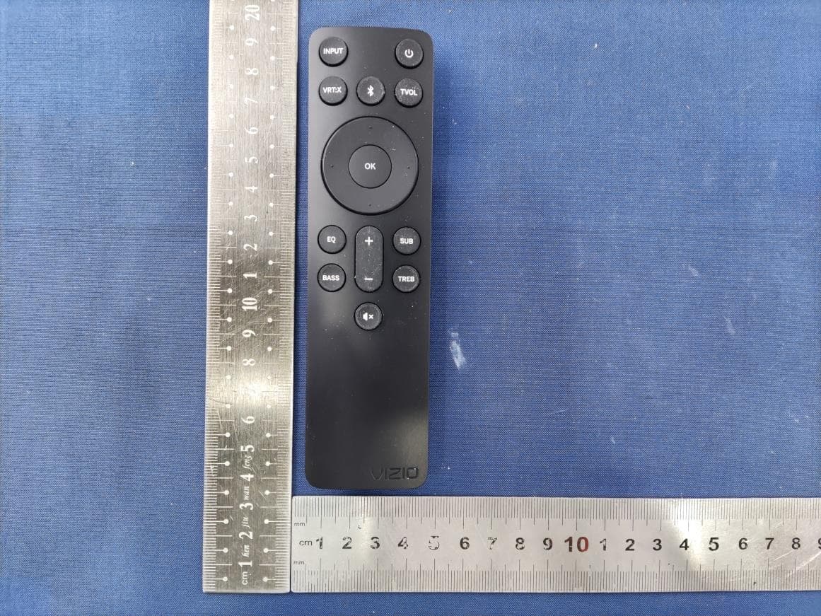
ZVASB000027
Nov 06, 20232.1 Soundbar System
Equipment Class
DSS - Part 15 Spread Spectrum Transmitter