ZVD-S0000AZ0R3Eco-Sign ZigBee Gateway
PERVASIVE DISPLAYS INC.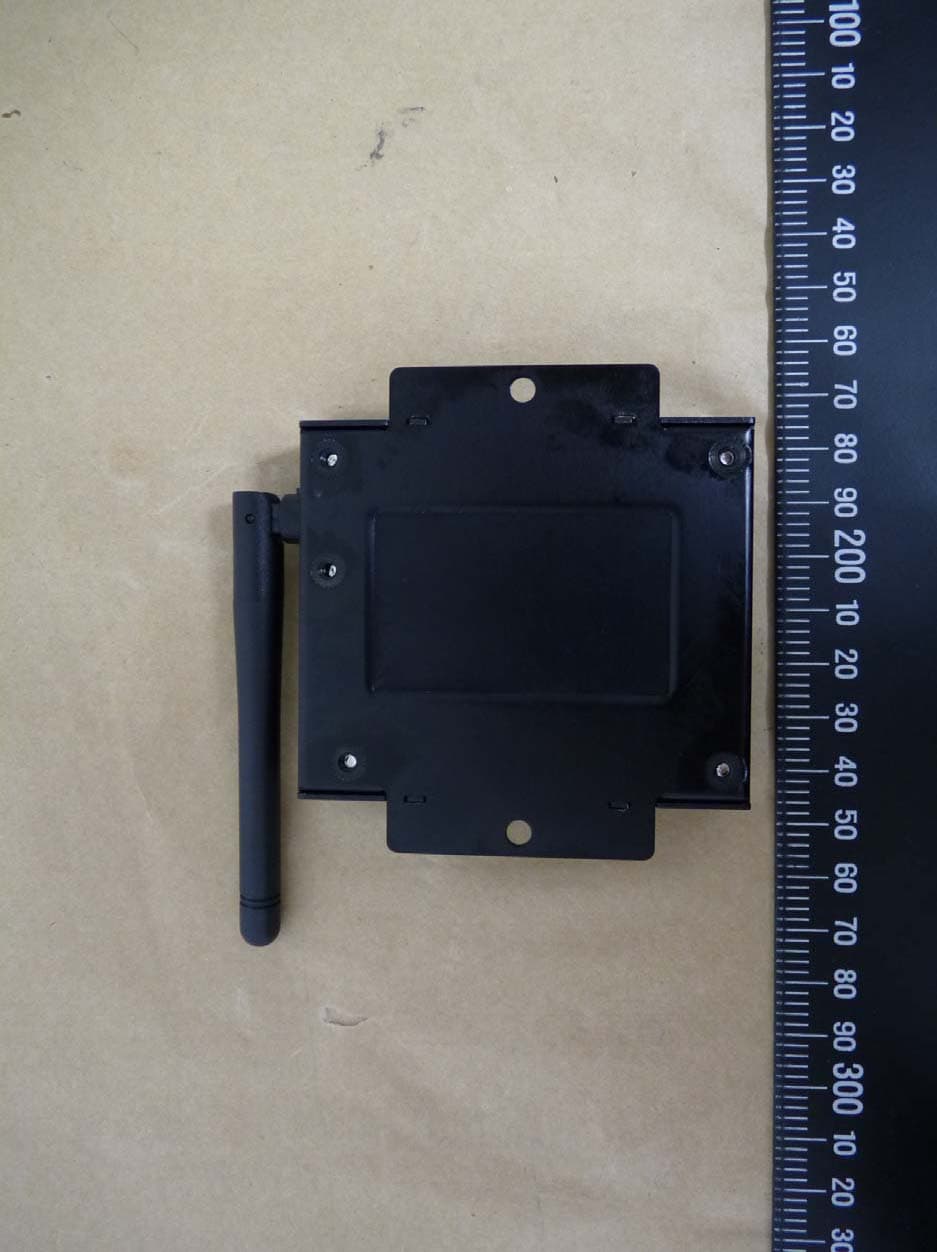
Click to zoom
Application Details
- Equipment Class
- DTS - Digital Transmission System
- Date of Grant
- Nov 21, 2011
- Application Purpose
- Original Equipment
- Date of Application
- Nov 21, 2011
- Equipment Note
- Eco-Sign ZigBee Gateway
- Frequency Range
- 2405.00000000 - 2480.00000000
- Company
- PERVASIVE DISPLAYS INC.
- Country
- Taiwan
Documents & Files
Document Text
Text extracted from the exhibit documents filed with the FCC. Open a document above to read the original.
Users Manual
i ECO-Sign User Manual Rev. 1.0 July, 2011 Pervasive Displays Inc. Te l:+886-6-2795399 | Fax:+886-6-2795300 ii Contents I. Introduction ............................................................................................ 1 1. What is the ECO-Sign Solution? ......................................................... 1 2. ZigBee Wireless Technology ............................................................... 2 3. ZigBee Topologies ............................................................................ 3 4. Node Types ..................................................................................... 4 5. ECO-Sign Model & Composed of Elements ........................................... 5 II. Pre-Installation ....................................................................................... 7 III. Quick Start with ECO-Sign ........................................................................ 8 I V. Quick Start with Template Design ............................................................ 10 V. Software Installation .............................................................................. 11 1. Supported Operating Systems.......................................................... 11 2. Instructions ................................................................................... 11 VI. Hardware Installation ............................................................................. 12 1. Overview ....................................................................................... 12 2. Mounting ECO-Sign ........................................................................ 13 3. LED Indicator (on Device) ............................................................... 18 4. Connecting Coordinator / Router ...................................................... 18 5. Recharging Device .......................................................................... 19 VII. Coordinator Network Configuration .......................................................... 20 1. Communication Port ....................................................................... 20 2. Configure Coordinator ..................................................................... 21 3. Web Configuration .......................................................................... 23 VIII. Working with Device and Coordinator ....................................................... 26 1. Starting ESS (ECO-Sign System) ...................................................... 26 2. Coordinator ................................................................................... 27 3. Target ........................................................................................... 29 4. EPD Device .................................................................................... 31 5. Template ....................................................................................... 35 6. Schedule ....................................................................................... 40 7. Configuration ................................................................................. 41 iii 8. How does Eco-Sign work? ............................................................... 43 9. Information ................................................................................... 44 IX. How to update firmware? ....................................................................... 46 1. Naming rule .................................................................................. 46 2. Update tool ................................................................................... 46 User Manual of ECO-Sign v1.0 -1- Confidential I. Introduction 1. What is the ECO-Sign Solution? The ECO-Sign solution is a green, eco-friendly and low power signage solution which includes e-Paper devices with ZigBee wireless gateways and software. The ECO-Sign has ultra-low power consumption and provides wireless updates of the display. With no wires and rechargeable batteries the ECO-Sign is easy to install and is a perfect solution for office or factory automation, electronic shelf labels, e -Signage/e-POP, logistic or container applications. The included software has a powerful template designer and the built in scheduler provides an easy remote management tool. The solution is characterized by the following features: (1) Slim & Light: Fewer parts, simple electronics, no thermal concerns and less mechanical challenges. (2) Active Matrix TFT: Built in active-matrix electrophoretic display. (3) Paper Like: It is reflective, has a very wide viewing angle and excellent contrast. (4) Rechargeable Battery: 1 year operating time on a single charge. (5) Wireless: Without any power cord and network cables, the content can be updated wirelessly and controlled remotely. (6) Ultra Low Power Consumption: It is very energy efficient and allows you to define when the device sleeps or wakes up. (7) Color: It also provides area color for color requirements. (8) Secure: No OS, so impervious to hacker & virus. 128 bits AES (16 Bytes) security. (9) Lower Content Cost: Simple and straightforward. No need for computing power or memory overhead. (10) Low Maintenance: Light and Thin, easy to install and repair, less installation overhead. User Manual of ECO-Sign v1.0 -2- Confidential 2. ZigBee Wireless Technology ZigBee is a specification for a suite of high level communication protocols using small, low-power digital radios based on the IEEE 802.15.4 standard for Wireless Personal Area Networks (WPANs). The technology defined by the ZigBee specification is intended to be simpler and less expensive than other WPANs, such as Bluetooth. ZigBee is targeted at radio-frequency (RF) applications that require a low data rate, long battery life, and secure networking and is designed for wireless controls and sensors. ZigBee has two modes of operation: Active, also called WakeUp, and Sleep mode. In the active mode the device is communicating with oth…
Text truncated - open the document above for the full version.
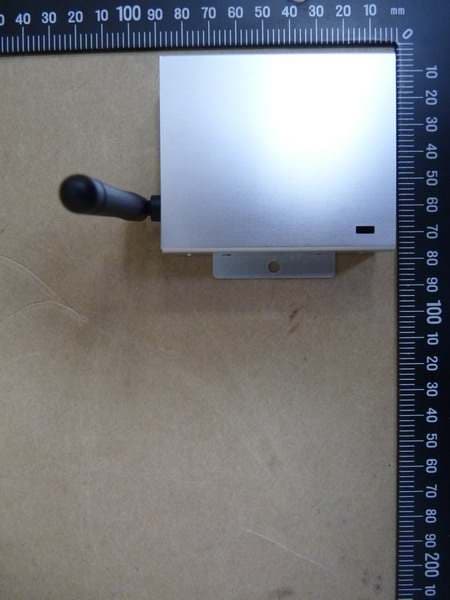
External Photos
Registration number: W6M21110-11911-FCC FCC ID: ZVD-S0000AZ0R3 Worldwide Testing Services(Taiwan) Co., Ltd.Appendix page 2 of 18 External Photos Registration number: W6M21110-11911-FCC FCC ID: ZVD-S0000AZ0R3 Worldwide Testing Services(Taiwan) Co., Ltd.Appendix page 3 of 18 Registration number: W6M21110-11911-FCC FCC ID: ZVD-S0000AZ0R3 Worldwide Testing Services(Taiwan) Co., Ltd.Appendix page 4 of 18 Registration number: W6M21110-11911-FCC FCC ID: ZVD-S0000AZ0R3 Worldwide Testing Services(Taiwan) Co., Ltd.Appendix page 5 of 18 Registration number: W6M21110-11911-FCC FCC ID: ZVD-S0000AZ0R3 Worldwide Testing Services(Taiwan) Co., Ltd.Appendix page 6 of 18 Registration number: W6M21110-11911-FCC FCC ID: ZVD-S0000AZ0R3 Worldwide Testing Services(Taiwan) Co., Ltd.Appendix page 7 of 18 Registration number: W6M21110-11911-FCC FCC ID: ZVD-S0000AZ0R3 Worldwide Testing Services(Taiwan) Co., Ltd.Appendix page 8 of 18 Registration number: W6M21110-11911-FCC FCC ID: ZVD-S0000AZ0R3 Worldwide Testing Services(Taiwan) Co., Ltd.Appendix page 9 of 18
Internal Photos
Registration number: W6M21110-11911-FCC FCC ID: ZVD-S0000AZ0R3 Worldwide Testing Services(Taiwan) Co., Ltd.Appendix page 10 of 18 Internal Photos Registration number: W6M21110-11911-FCC FCC ID: ZVD-S0000AZ0R3 Worldwide Testing Services(Taiwan) Co., Ltd.Appendix page 11 of 18 Registration number: W6M21110-11911-FCC FCC ID: ZVD-S0000AZ0R3 Worldwide Testing Services(Taiwan) Co., Ltd.Appendix page 12 of 18 Registration number: W6M21110-11911-FCC FCC ID: ZVD-S0000AZ0R3 Worldwide Testing Services(Taiwan) Co., Ltd.Appendix page 13 of 18 Registration number: W6M21110-11911-FCC FCC ID: ZVD-S0000AZ0R3 Worldwide Testing Services(Taiwan) Co., Ltd.Appendix page 14 of 18
RF Exposure Info
MPE Prediction FCC Rule: 15.247(b)(5) Systems operating under the provisions of this section shall be operated in a manner that ensures that the public is not exposed to radio frequency energy levels in excess of the Commission’s guidelines. See §1.1307(b)(1) of this Chapter. LIMITS FOR MAXIMUM PERMISSIBLE EXPOSURE (MPE) Frequency Range (MHz) Electric Field Strength (V/m) Magnetic Field Strength (A/m) Power Density (mW/cm2) Average time (minutes) (A)Limits For Occupational / Control Exposures 30-300 61.4 0.613 1.0 6 300-1500 ... ... F/300 6 1500-100,000 ... ... 5 6 (B)Limits For General Population / Uncontrolled Exposure 30-300 27.5 0.073 0.2 30 300-1500 ... ... F/1500 30 1500-100,000 ... ... 1.0 30 F = Frequency in MHz Prediction of MPE limit at a given distance Equation from page 18 of OET Bulletin 65, Edition 97-01 PG S = -------------- 4πR² where: S = power density P = power input to the antenna G = power gain of the antenna in the direction of interest relative to an isotropic radiator R = distance to the center of radiation of the antenna Maximum peak output power at antenna input terminal: 15.15 (dBm) Maximum peak output power at antenna input terminal: 32.73 (mW) Antenna gain(maximal): 2.49 (dBi) Prediction distance: 20 (cm) Prediction frequency: 2405 (MHz) MPE limit for uncontrolled exposure at prediction frequency: 1.0 (mW/cm²) Power density at prediction frequency: 0.011525 (mW/cm²) The manual instruct the user to install and operate the device in a minimum distance of 20 cm between antenna and the user’s body.
Test Report
of Applicant: PERVASIVE DISPLAYS INC. Address: No.71, Delun Rd., Rende Dist., Tainan City 71743, Taiwan (R.O.C.) Tested and Prepared by Worldwide Testing Services (Taiwan) Co., Ltd. FCC Registration No.: 930600 Industry Canada filed test laboratory Reg. No. IC 5679A-1 A2LA Accredited No.: 2732.01 Report No.: W6M21110-11911-C-1 6F, NO. 58, LANE 188, RUEY-KUANG RD., NEIHU TAIPEI 114, TAIWAN, R.O.C. TEL: 886-2-66068877 FAX: 886-2-66068879 E-mail: [email protected] FCC PART 15 SUBPART C TEST REPORT for Eco-Sign ZigBee Gateway Model No.: S0000AZ0R3 FCC ID: ZVD-S0000AZ0R3 Registration number: W6M21110-11911-C-1 FCC ID: ZVD-S0000AZ0R3 Worldwide Testing Services(Taiwan) Co., Ltd. Page 1 of 34 TABLE OF CONTENTS 1 General Information............................................................................................................................2 1.1 Notes ...........................................................................................................................................2 1.2 Testing laboratory .......................................................................................................................3 1.2.1 Location ..................................................................................................................................3 1.2.2 Details of accreditation status ................................................................................................3 1.3 Details of approval holder...........................................................................................................4 1.4 Application details ......................................................................................................................4 1.5 General information of Test item................................................................................................4 1.6 Test standards .............................................................................................................................5 2 Technical test ......................................................................................................................................6 2.1 Summary of test results...............................................................................................................6 2.2 Test environment ........................................................................................................................6 2.3 Test Equipment List ....................................................................................................................7 2.4 General Test Procedure.............................................................................................................11 3 Test results (enclosure) .....................................................................................................................13 3.1 Peak Output Power (transmitter) ..............................................................................................14 3.2 Equivalent isotropic radiated power .........................................................................................17 3.3 RF Exposure Compliance Requirements ..................................................................................17 3.4 Transmitter Radiated Emissions in Restricted Bands ...............................................................18 3.5 Spurious Emissions (tx) ............................................................................................................19 3.6 Radiated Emission on the band edge ........................................................................................23 3.7 Minimum 6 dB Bandwidth .......................................................................................................25 3.8 Peak Power Spectral Density ....................................................................................................28 3.9 Radiated Emission from Digital Part ........................................................................................31 3.10 Power Line Conducted Emission..............................................................................................32 Appendix...................................................................................................................................................34 Registration number: W6M21110-11911-C-1 FCC ID: ZVD-S0000AZ0R3 Worldwide Testing Services(Taiwan) Co., Ltd. Page 2 of 34 1 General Information 1.1 Notes The purpose of conformity testing is to increase the probability of adherence to the essential requirements or conformity specifications, as appropriate. The complexity of the technical specifications, however, means that full and thorough testing is impractical for both technical and economic reasons. Furthermore, there is no guarantee that a test sample which has passed all the relevant tests conforms to a specification. Neither is there any guarantee that such a test sample will interwork with other genuinely open systems. The existence of the tests nevertheless provides the confidence that the test sample possesses the qualities as maintained and that is performance generally conforms to representative cases of communications equipment. The test results of this test report relate exclusively to the item tested as specified in 1.5. The test report may only be reproduced or published in full. Reproduction or publication of extracts from the report requires the prior written approval of the Worldwide Testing Services(Taiwan) Co., Ltd. Specific Conditions: Usage of the hereunder tested device in combination with other integrated or external antennas requires at least additional output power measurements, spurious emission measurements, conducted emission measurements (AC supply lines) and radio frequency exposure evaluations for each individual configuration performed, for certification by FCC. This report is related to FCC Part 15 C (DSSS device). Tester: October 27, 2011 Rick Chen Date WTS-L…
Text truncated - open the document above for the full version.
Test Setup Photos
Registration number: W6M21110-11911-FCC FCC ID: ZVD-S0000AZ0R3 Worldwide Testing Services(Taiwan) Co., Ltd.Appendix page 15 of 18 Set Up Photo of Radiated Emission EMI Mode Below 1GHz Registration number: W6M21110-11911-FCC FCC ID: ZVD-S0000AZ0R3 Worldwide Testing Services(Taiwan) Co., Ltd.Appendix page 16 of 18 Above 1GHz Registration number: W6M21110-11911-FCC FCC ID: ZVD-S0000AZ0R3 Worldwide Testing Services(Taiwan) Co., Ltd.Appendix page 17 of 18 RF Mode Registration number: W6M21110-11911-FCC FCC ID: ZVD-S0000AZ0R3 Worldwide Testing Services(Taiwan) Co., Ltd.Appendix page 18 of 18 Set Up Photo of Conducted Emission
Contact Information
Applicant
Abnern Chen(Project Manager)
Technical Contact
Worldwide Testing Services (Taiwan) Co., Ltd.Tse-Ming Chang
[email protected]+886-2-6606-8877
6F., No. 58, Lane 188, Ruey Kuand Rd., Neihu · Taipei · Taiwan
Test Firm
Worldwide Testing Services (Taiwan) Co. Ltd.Chang Tse-Ming
Technical Specifications
| # | Rule Parts | Frequency Range | Power Output |
|---|---|---|---|
| 1 | 15C | 2.40 GHz - 2.48 GHz | 33.00 mW |
Other Applications from PERVASIVE DISPLAYS INC.
ZVD-S0000AZ0C3
Sep 22, 2011Eco-Sign ZigBee Gateway
Equipment Class
DTS - Digital Transmission System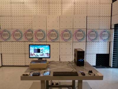
ZVD-SW074AZ1D2
Sep 22, 2011Eco-Sign 7.4" Device
Equipment Class
DTS - Digital Transmission System