ZVS-NVX-DCKAudiOffice
invoxia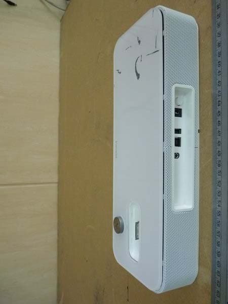
Click to zoom
Application Details
- Equipment Class
- DSS - Part 15 Spread Spectrum Transmitter
- Date of Grant
- May 08, 2012
- Application Purpose
- Original Equipment
- Date of Application
- May 08, 2012
- Equipment Note
- AudiOffice
- Frequency Range
- 2402.00000000 - 2480.00000000
- Company
- invoxia
- Country
- France
Documents & Files
Document Text
Text extracted from the exhibit documents filed with the FCC. Open a document above to read the original.
Users Manual
•Made for conference, mobile, voip apps and video calls •An office dock that integrates the iPhone/iPod/iPad •A restful and uncluterred design •A playful and practical magnetic smart holder AudiOffice The best office phone for professionals The best office phone for professionalsThe best office phone for professionals The best office phone for professionals Transforming the iPhone. The ultimate office sound system The ultimate office sound systemThe ultimate office sound system The ultimate office sound system •Matchless sound quality and performance for music and voice •A device dedicated to your voip applications •Your computer external sound system •Use it with any Bluetooth device •A smart object regularly updated •Compliant with: – iPod touch 4th generation and iPod touch 3rd generation – iPhone 4S, iPhone 4 and iPhone 3GS – iPad 2 and iPad Connectivity ConnectivityConnectivity Connectivity •Bluetooth 2.1 •2 USB ports: 1 for the handset, 1slave for the PC •Connection via 30 point connector or Bluetooth •Universal Dock Adapter for iPod touch (3rd and 4th generation), iPhone 4S, iPhone 4 , iPhone 3GS •1 audio jack 3,5 •On/Off button Technical specifications Technical specificationsTechnical specifications Technical specifications •Processor ARM Cortex A8 •Power supply: 100-240V/ 5V 3A AC adapter •Dimensions: 31x11,5x7cm (IP Phone), 17,8x5,1x3,2cm (handset) •Temperature range: 0°C – 40°C, 32°F-104°F •Weight: 1,3 kg •Humidity: 10% - 90% AudiOffice Highlights HighlightsHighlights Highlights In Vivo Acoustic In Vivo Acoustic In Vivo Acoustic In Vivo Acoustic technology : •4 broadband speakers •2 digital microphones •Immersive spatial sound Design DesignDesign Design Designed by invoxia, Paris. Assembled in China. Warranty WarrantyWarranty Warranty 1 year warranty. © 2012 invoxia. All Rights reserved. www.invoxia.com Issue date: 2012-02-27 Specifications are subject to change without notice. Invoxia ®, ™ Experience your phone, In Vivo Acoustic ®, Smart holder ® and related trademarks, names and logos are the property of invoxia. iPhone, iPod, iPad and iTunes are trademarks of Apple Inc. Bluetooth ® is a trademark of Bluetooth SIG. Federal Communication Commission Interference Statement This equipment has been tested and found to comply with the limits for a Class B digital device, pursuant to Part 15 of the FCC Rules. These limits are designed to provide reasonable protection against harmful interference in a residential installation. This equipment generates, uses and can radiate radio frequency energy and, if not installed and used in accordance with the instructions, may cause harmful interference to radio communications. However, there is no guarantee that interference will not occur in a particular installation. If this equipment does cause harmful interference to radio or television reception, which can be determined by turning the equipment off and on, the user is encouraged to try to correct the interference by one of the following measures: . Reorient or relocate the receiving antenna. . Increase the separation between the equipment and receiver. . Connect the equipment into an outlet on a circuit different from that to which the receiver is connected. . Consult the dealer or an experienced radio/TV technician for help. FCC Caution: To assure continued compliance, any changes or modifications not expressly approved by the party responsible for compliance could void the user's authority to operate this equipment. (Example - use only shielded interface cables when connecting to computer or peripheral devices). FCC Radiation Exposure Statement This equipment complies with FCC RF radiation exposure limits set forth for an uncontrolled environment. This equipment should be installed and operated with a minimum distance of 20 centimeters between the radiator and your body. This transmitter must not be co-located or operating in conjunction with any other antenna or transmitter. The antennas used for this transmitter must be installed to provide a separation distance of at least 20 cm from all persons and must not be co-located or operating in conjunction with any other antenna or transmitter. This device complies with Part 15 of the FCC Rules. Operation is subject to the following two conditions: (1) This device may not cause harmful interference, and (2) This device must accept any interference received, including interference that may cause undesired operation.
External Photos
Registration number: W6M21205-12414-FCC FCC ID: ZVS-NVX-DCK Worldwide Testing Services(Taiwan) Co., Ltd.Appendix page 2 of 25 External Photos Registration number: W6M21205-12414-FCC FCC ID: ZVS-NVX-DCK Worldwide Testing Services(Taiwan) Co., Ltd.Appendix page 3 of 25 Registration number: W6M21205-12414-FCC FCC ID: ZVS-NVX-DCK Worldwide Testing Services(Taiwan) Co., Ltd.Appendix page 4 of 25 Registration number: W6M21205-12414-FCC FCC ID: ZVS-NVX-DCK Worldwide Testing Services(Taiwan) Co., Ltd.Appendix page 5 of 25 Registration number: W6M21205-12414-FCC FCC ID: ZVS-NVX-DCK Worldwide Testing Services(Taiwan) Co., Ltd.Appendix page 6 of 25 Registration number: W6M21205-12414-FCC FCC ID: ZVS-NVX-DCK Worldwide Testing Services(Taiwan) Co., Ltd.Appendix page 7 of 25 Registration number: W6M21205-12414-FCC FCC ID: ZVS-NVX-DCK Worldwide Testing Services(Taiwan) Co., Ltd.Appendix page 8 of 25 Registration number: W6M21205-12414-FCC FCC ID: ZVS-NVX-DCK Worldwide Testing Services(Taiwan) Co., Ltd.Appendix page 9 of 25
ID Label/Location Info
NVX DCK_FCC ID label location
Internal Photos
Registration number: W6M21205-12414-FCC FCC ID: ZVS-NVX-DCK Worldwide Testing Services(Taiwan) Co., Ltd.Appendix page 10 of 25 Internal Photos Registration number: W6M21205-12414-FCC FCC ID: ZVS-NVX-DCK Worldwide Testing Services(Taiwan) Co., Ltd.Appendix page 11 of 25 Registration number: W6M21205-12414-FCC FCC ID: ZVS-NVX-DCK Worldwide Testing Services(Taiwan) Co., Ltd.Appendix page 12 of 25 Registration number: W6M21205-12414-FCC FCC ID: ZVS-NVX-DCK Worldwide Testing Services(Taiwan) Co., Ltd.Appendix page 13 of 25 Registration number: W6M21205-12414-FCC FCC ID: ZVS-NVX-DCK Worldwide Testing Services(Taiwan) Co., Ltd.Appendix page 14 of 25 Registration number: W6M21205-12414-FCC FCC ID: ZVS-NVX-DCK Worldwide Testing Services(Taiwan) Co., Ltd.Appendix page 15 of 25 Registration number: W6M21205-12414-FCC FCC ID: ZVS-NVX-DCK Worldwide Testing Services(Taiwan) Co., Ltd.Appendix page 16 of 25 Registration number: W6M21205-12414-FCC FCC ID: ZVS-NVX-DCK Worldwide Testing Services(Taiwan) Co., Ltd.Appendix page 17 of 25 Registration number: W6M21205-12414-FCC FCC ID: ZVS-NVX-DCK Worldwide Testing Services(Taiwan) Co., Ltd.Appendix page 18 of 25
RF Exposure Info
MPE Prediction FCC Rule: 15.247(b)(5) Systems operating under the provisions of this section shall be operated in a manner that ensures that the public is not exposed to radio frequency energy levels in excess of the Commission’s guidelines. See §1.1307(b)(1) of this Chapter. LIMITS FOR MAXIMUM PERMISSIBLE EXPOSURE (MPE) Frequency Range (MHz) Electric Field Strength (V/m) Magnetic Field Strength (A/m) Power Density (mW/cm2) Average time (minutes) (A)Limits For Occupational / Control Exposures 30-300 61.4 0.613 1.0 6 300-1500 ... ... F/300 6 1500-100,000 ... ... 5 6 (B)Limits For General Population / Uncontrolled Exposure 30-300 27.5 0.073 0.2 30 300-1500 ... ... F/1500 30 1500-100,000 ... ... 1.0 30 F = Frequency in MHz Prediction of MPE limit at a given distance Equation from page 18 of OET Bulletin 65, Edition 97-01 PG S = -------------- 4πR² where: S = power density P = power input to the antenna G = power gain of the antenna in the direction of interest relative to an isotropic radiator R = distance to the center of radiation of the antenna Maximum peak output power at antenna input terminal: 9.90(dBm) Maximum peak output power at antenna input terminal: 9.7724 (mW) Antenna gain(maximal): 3 (dBi) Prediction distance: 20 (cm) Prediction frequency: 2402 (MHz) MPE limit for uncontrolled exposure at prediction frequency: 1.0 (mW/cm²) Power density at prediction frequency: 0.00388 (mW/cm²) The manual instruct the user to install and operate the device in a minimum distance of 20 cm between antenna and the user’s body.
Test Report
of Applicant: invoxia Address: 87 rue du Gouverneur Général Eboué 92130 Issy les Moulineaux France Tested and Prepared by Worldwide Testing Services (Taiwan) Co., Ltd. FCC Registration No.: 930600 Industry Canada filed test laboratory Reg. No. IC 5679A-1 A2LA Accredited No.: 2732.01 Report No.: W6M21205-12414-C-1 6F, NO. 58, LANE 188, RUEY-KUANG RD., NEIHU TAIPEI 114, TAIWAN, R.O.C. TEL: 886-2-66068877 FAX: 886-2-66068879 E-mail: [email protected] FCC PART 15 SUBPART C TEST REPORT for AudiOffice Model No.: NVX DCK FCC ID: ZVS-NVX-DCK Registration number: W6M21205-12414-C-1 FCC ID: ZVS-NVX-DCK Worldwide Testing Services(Taiwan) Co., Ltd. Page 1 of 49 TABLE OF CONTENTS 1 GENERAL INFORMATION ...................................................................................................... 2 1.1 Notes....................................................................................................2 1.2 Testing laboratory.....................................................................................3 1.2.1 Location......................................................................................................................3 1.2.2 Details of accreditation status....................................................................................3 1.3 Details of approval holder............................................................................3 1.4 Application details....................................................................................4 1.5 General information of Test item......................................................................................... 4 1.6 Test standards..........................................................................................5 2 TECHNICAL TEST .................................................................................................................... 6 2.1 Summary of test results..............................................................................6 2.2 Test environment......................................................................................6 2.3 Test Equipment List...................................................................................7 2.4 General Test Procedure..............................................................................11 3 TEST RESULTS (ENCLOSURE) ............................................................................................ 13 3.1 Peak Output Power (transmitter) ....................................................................................... 14 3.2 RF Exposure Compliance Requirements ........................................................................... 18 3.3 Out of Band Radiated Emissions ....................................................................................... 18 3.4 Transmitter Radiated Emissions in restricted Bands ......................................................... 19 3.5 Spurious emissions (tx)..............................................................................20 3.6 Carrier Frequency Separation.......................................................................23 3.7 Number of Hopping Frequencies...................................................................26 3.7.1 Pseudorandom Frequency Hopping Sequence........................................................28 3.7.2 Coordination of hopping sequences to other transmitters.......................................28 3.7.3 System Receiver Hopping Capability.......................................................................28 3.8 Time of Occupancy (Dwell Time).................................................................29 3.9 20dB Bandwidth.....................................................................................35 3.9.1 System Receiver Input Bandwidth............................................................................38 3.10 Band-edge Compliance of RF Emissions.........................................................39 3.11 Radiated Emissions from Digital Part ............................................................................... 44 3.12 Power Line Conducted Emission....................................................................................... 45 Registration number: W6M21205-12414-C-1 FCC ID: ZVS-NVX-DCK Worldwide Testing Services(Taiwan) Co., Ltd. Page 2 of 49 1 General Information 1.1 Notes The purpose of conformity testing is to increase the probability of adherence to the essential requirements or conformity specifications, as appropriate. The complexity of the technical specifications, however, means that full and thorough testing is impractical for both technical and economic reasons. Furthermore, there is no guarantee that a test sample which has passed all the relevant tests conforms to a specification. Neither is there any guarantee that such a test sample will interwork with other genuinely open systems. The existence of the tests nevertheless provides the confidence that the test sample possesses the qualities as maintained and that is performance generally conforms to representative cases of communications equipment. The test results of this test report relate exclusively to the item tested as specified in 1.5. The test report may only be reproduced or published in full. Reproduction or publication of extracts from the report requires the prior written approval of the Worldwide Testing Services(Taiwan) Co., Ltd. Tester: May 08, 2012 Rick Chen Date WTS-Lab. Name Signature Technical responsibility for area of testing: May 08, 2012 Danny Sung Date WTS Name Signature Registration number: W6M21205-12414-C-1 FCC ID: ZVS-NVX-DCK Worldwide Testing Services(Taiwan) Co., Ltd. Page 3 of 49 1.2 Testing laboratory 1.2.1 Location OATS No.5-1, Lishui, Shuang Sing Village, Wanli Dist., New Taipei City 207, Taiwan (R.O.C.) 3 meter semi-anechoic chamber No.35, Aly. 21, Ln. 228, Ankang Rd., Neihu Dist., Taipei City 114, Taiwan (R.O.C.) TEL:886-2-6613-0228 FAX:886-2-2791-5046 Company Worldwide Te…
Text truncated - open the document above for the full version.
Test Setup Photos
Registration number: W6M21205-12414-FCC FCC ID: ZVS-NVX-DCK Worldwide Testing Services(Taiwan) Co., Ltd.Appendix page 19 of 25 Set Up Photo of Radiated Emission EMI mode_Normal Below 1GHz Registration number: W6M21205-12414-FCC FCC ID: ZVS-NVX-DCK Worldwide Testing Services(Taiwan) Co., Ltd.Appendix page 20 of 25 Above 1GHz Registration number: W6M21205-12414-FCC FCC ID: ZVS-NVX-DCK Worldwide Testing Services(Taiwan) Co., Ltd.Appendix page 21 of 25 EMI mode_USB Below 1GHz Registration number: W6M21205-12414-FCC FCC ID: ZVS-NVX-DCK Worldwide Testing Services(Taiwan) Co., Ltd.Appendix page 22 of 25 Above 1GHz Registration number: W6M21205-12414-FCC FCC ID: ZVS-NVX-DCK Worldwide Testing Services(Taiwan) Co., Ltd.Appendix page 23 of 25 RF mode Registration number: W6M21205-12414-FCC FCC ID: ZVS-NVX-DCK Worldwide Testing Services(Taiwan) Co., Ltd.Appendix page 24 of 25 Set Up Photo of Conducted Emission Normal Registration number: W6M21205-12414-FCC FCC ID: ZVS-NVX-DCK Worldwide Testing Services(Taiwan) Co., Ltd.Appendix page 25 of 25 USB
Contact Information
Applicant
Fabrice DEVIGE(ELECTRONIC DIRECTOR)
Technical Contact
Worldwide Testing Services (Taiwan) Co., Ltd.Tse-Ming Chang
[email protected]+886-2-6606-8877
6F., No. 58, Lane 188, Ruey Kuand Rd., Neihu · Taipei · Taiwan
Test Firm
Worldwide Testing Services (Taiwan) Co. Ltd.Chang Tse-Ming
Technical Specifications
| # | Rule Parts | Frequency Range | Power Output |
|---|---|---|---|
| 1 | 15C | 2.40 GHz - 2.48 GHz | 9.80 mW |
Other Applications from invoxia
ZVS-LWT3
Jan 19, 2020LWT3
Equipment Class
DTS - Digital Transmission System
ZVS-KTP1
Jul 30, 2015KTP1
Equipment Class
DTS - Digital Transmission System
ZVS-E169
Jan 13, 2014DTP2
Equipment Class
DSS - Part 15 Spread Spectrum Transmitter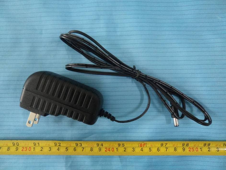
ZVS-DTP3
Dec 19, 2013DTP 3
Equipment Class
DSS - Part 15 Spread Spectrum Transmitter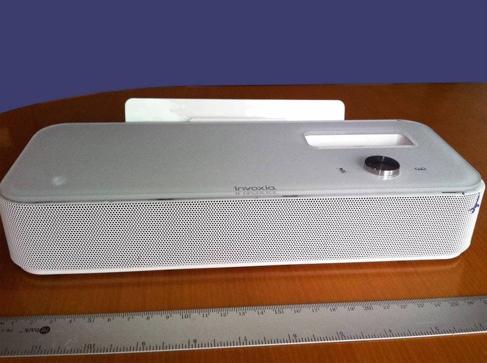
ZVS-NVX-DTP2
Apr 07, 2013NVX2
Equipment Class
DSS - Part 15 Spread Spectrum Transmitter