2A482-P1XBaseus Neckband Wireless Earphones
Shenzhen Baseus Technology Co., Ltd.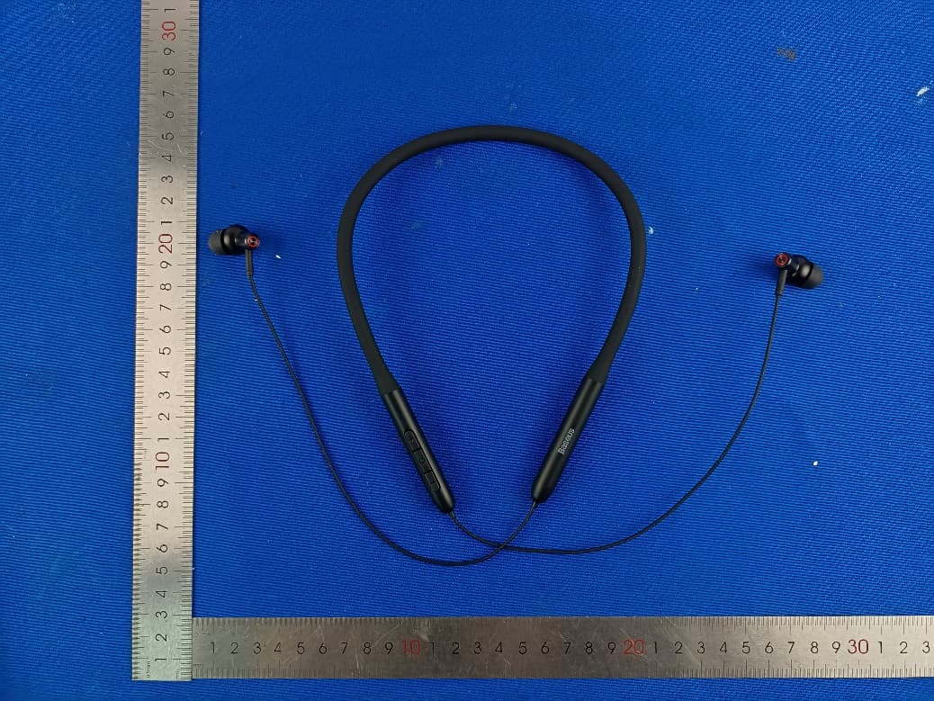
Click to zoom
Application Details
- Equipment Class
- DTS - Digital Transmission System
- Date of Grant
- Nov 19, 2022
- Application Purpose
- Original Equipment
- Date of Application
- Nov 17, 2022
- Equipment Note
- Baseus Neckband Wireless Earphones
- Frequency Range
- 2402.00000000 - 2480.00000000
- Country
- China
Documents & Files
Document Text
Text extracted from the exhibit documents filed with the FCC. Open a document above to read the original.
Users Manual
使用说明书 倍思 Bowie系列 P1x 颈挂式蓝牙耳机 使用产品前请仔细阅读本使用说明,并请妥善保管。 User Manual Baseus Bowie P1x Neckband Wireless Earphones Please read this user manual carefully before use and keep it for future reference. 01 产品连接步骤 音量-键 音量+键 耳机指示灯 / 麦克风孔 多功能按键 充电接口 开机 蓝牙连接 关机 长按 2s 多功能按键,耳机自动进入开机状态 打开手机蓝牙功能,进入搜索配对状态 选择设备型号:Baseus Bowie P1x 长按 4s 多功能按键,耳机进入关机状态 1 2 3 CN K Baseus Bowie P1x 1000053578 DZ-JD3/TM1 倍思 Bowie系列 P1x 入耳颈挂式蓝牙耳机 说明书\封面封底128g铜版纸过连线哑油+内页65g轻涂纸\单 黑印刷\一颗骑马钉\16P\60*100mm\ROHS 张敏 2022.09.13 唐斌峰 PB3822Z-P0A0 此页面空白印刷,印刷时请删除内容 0203 产品功能操作 充电电量指示灯 音乐模式: 电话模式: 播放 / 暂停:单击多功能按键 上一曲:长按音量“-”键 1.5 秒 下一曲:长按音量“+”键 1.5 秒 音量减:单击音量“-”键 音量加:单击音量“+”键 低延迟模式切换:双击多功能按键 激活手机语音助手:三击多功能按键 接听 / 挂断:单击多功能按键 拒接:长按 2 秒多功能按键 连接电源为耳机充电(充电中显示红灯,电源充满时显示蓝灯) 恢复出厂设置 产品安全信息 关闭手机蓝牙,同时长按音量“+”键和音量“-”键 4 秒,蓝灯闪烁三次代表成功。 在使用本产品前请阅读所有的指示和警告,不规范使用将会给产品或人身安全带来损害。 1. 产品内含电池,请勿将本产品暴露在强日照或暖炉等过热环境中。请勿将本产品储存在高温,强光及强磁场环境下。 2. 产品不可放置在火源附近等恶劣环境中,禁止敲击、投掷、践踏、挤压或投入火中,若出现鼓胀,请勿使用。 3. 产品使用环境温度:0~45°C。 4. 请勿违反产品说明书不恰当使用,造成产品损坏或危及人身财产安全,后果自行承担。 5. 非专业人员严禁分解本产品,否则可能会导致起火,甚至彻底损坏本产品。 6. 请勿使用超出本产品输出电流负载(用电器),超出负载会自动停止工作。 7. 请定期用干净的棉布对耳机充电触点进行清洁,以避免因长期不清洁导致耳机出现无法充电或开机的情况。 8. 请勿将本产品置于水中(或洗衣机中 ),若产品出现进水情况,请等待其自然晾干后再使用。 0405 电子信息产品有害物质声明 本表格依据 SJ/T 11364 的规定编制。 O:表示该有害物质在该部件所有均质材料中的含量均在 GB/T 26572 标准规定的限量要求以下。 X:表辅有害物质至少在该部件某一均质材料中的含量超出 GB/T 26572 标准规定的限量要求。 该产品符合欧盟 RoHS 2.0 指令(2011/65/EU) 温馨提示:5 年图标是指“环保有效使用期限”,不是产品质量保证期限。电子产品均含有铅、汞、镉等有害物质,一旦超期使用,有 害物质将可能因为发生外泄或突变,对环境造成污染,或对人体及人身财产造成严重损害。“环保使用期限”,意为所有的电子产品 都将被要求在此有效限期内使用,超过安全使用年限之后出现的安全风险问题,我们将不再对产品质量负责。 产品参数 名称:倍思 颈挂式蓝牙耳机 型号:Baseus Bowie P1x 蓝牙版本:V5.3 通讯距离:10 米 听歌时间:约 25 小时(70% 音量) 电池容量:170mAh/0.629Wh(耳机) * 以上数据来源 Baseus(倍思)实验室测定值,但因客观环境改变数据会有所不同或误差。 耳机额定输入:DC5V 100mA 耳机额定消耗电流:7mA 充电时间:约 1.5 小时 频响范围:20Hz-20kHz 充电接口:Micro-USB 适用:具有蓝牙功能的播放设备 0607 Connection Steps Volume - button Volume + button Earphone indicator/ Microphone jack Multifunction button Charging port Power on Wireless connection Power off Press and hold the multifunction button for 2s. The earphones automatically enter the power-on state. Turn on wireless mode on your phone to search and pair the earphones. Select device model:Baseus Bowie P1x Press and hold the multifunction button for 4s. The earphones will turn off. 1 2 3 包装清单 充电线 *1pcs 耳机 *1pcs 说明书 *1pcs 保修卡 *1pcs 此设备符合欧盟指令 2012/19/EU 和欧盟指令 2006/66/EU 的规定,此设备不得与普通废弃物一起处理,必须回收利用。 此符号标明本产品不得作为生活垃圾处理,而必须将本产品交至相应的废品回收站,进行电子电气设备回收处理。 特此申明, 深圳市倍思科技有限公司的产品型号为:Baseus Bowie P1x 符合欧盟指令 2014/53/EU 及 2011/65/ EU 的规定。欧盟符合性声明的全文可在以下网站查询:www.baseus.com EN 耳帽 *4pcs 0809 Restore to default settings Turn off the wireless on the mobile phone. Press and hold the Volume+ and Volume- buttons simultaneously for 4s. When the blue indicator blinks 3 times, the operation is successful. Operation Instructions Music mode: Call mode: Play/Pause: Press the multifunction button. Previous: Press and hold the Volume- button for 1.5s. Next: Press and hold the Volume+ button for 1.5s. Volume down: Press the Volume- button. Volume up: Press the Volume+ button. Switching to low latency mode: Double-press the multifunction button. Activating Voice Assistant: Press the multifunction button three times. Answer/Release a call: Press the multifunction button. Reject a call: Press and hold the multifunction button for 2s. Charging power indicator Connect to the power supply to charge the earphones (the red indicator is on during charging. The blue indicator is on when the battery is fully charged). Product safety information Improper use of the product can easily cause damage to the product or may endanger personal and property safety. 1. The battery is included in the product. Please avoid exposing your product to the sunlight, electric heater or similar overheating enviroments. Do not store the product in high temperature, strong light and strong magnetic places. 2. Do not keep it in other harsh environments such as fire source. Intense physical actions such as knocking, throwing, trampling on and squeezing etc. shall be avoided. Do not use it in case of expansion. 3. The ambient temperature of product is 0~45°C . 4. Inappropriate use of the product against this user manual or ignoring warnings can easily cause damage the product or may endanger personal and property safety. Consumer shall bear for all the consequences, to which our company will not assume any legal liability. 5. Decomposition of this product by non-professionals is strictly prohibited. 6. Do not use a load (electrical appliances) that exceeds the output current of this product. A circuit protection mechanism is built-in to automatically stop working if loads exceed. 7. Please use a clean cotton cloth to clean the charging contacts of earphones regularly to prevent it from failing to charge or turn on due to missing cleaning for a long time. 8. Do not put this product in water (or washing machine). If water enters the product, let it dry naturally before using it. 1011 Product Specifications Name: Baseus Neckband Wireless Earphones Model No.: Baseus Bowie P1x Wireless Version: V5.3 Communication distance: 10m Music playing time: About 25 hours (volume at 70%) Battery capacity: 170mAh/0,629Wh (earphones) *The above data are measured by the Baseus laboratory, the actual use will be slightly different depending on the specific circumstances. Earphone rated input: DC5V 100mA Earphone rated consumption current : 7mA Fully charging time: About 1.5 hours Frequency response range: 20 Hz-20 kHz Charge interface: Micro-USB Suitable for: Compatible with most of wireless devices Package Including Changes or modifications not expressly approved by the party responsible for compliance could void the user’s authority to operate the equipment. This device complies with Part 15 of the FCC Rules. Operation is subject to the following two conditions: (1) this device may not cause harmful interference, and (2) this device must accept any interference received, including interference that may cause undesired operation. Note: This equipment has been tested and found to comply with the limits for…
Text truncated - open the document above for the full version.
Cover Letter(s)
C5266091_X8_Ed.1 1/1 Letter of Authorization Company: Shenzhen Baseus Technology Co., Ltd. Address: 2th Floor, Building B, Baseus Intelligence Park, No.2008, Xuegang Rd, Gangtou Community, Bantian Street, Longgang District, Shenzhen. Product Name: Baseus Neckband Wireless Earphones Model Number: Baseus Bowie P1x FCC Identifier: 2A482-P1X We authorize LGAI Technological Center S.A., Ronda de la Font del Carme, s/n, 08193 Bellaterra, Spain, to act on our behalf on all matters concerning the above named equipment. Any individual within LGAI Technological Center S.A. is authorized to act on our behalf and take action on the application. We declare that authorize LGAI Technological Center S.A., Ronda de la Font del Carme, s/n, 08193 Bellaterra, Spain, is allowed to forward all information related to the approval project to the Federal Communication Commission and to discuss any issues concerning the approval application. Any and all acts carried out by LGAI Technological Center S.A. on our behalf shall have the same effect as acts of our own. Name: Zhang Mao Date: 11/15/2022 Title: Certified Engineer Signature of applicant:
Cover Letter(s)
C5266091_X10_Ed.2 1/1 Shenzhen Baseus Technology Co., Ltd. Office of Engineering Technology Federal Communications Commission 7435 Oakland Mills Road Columbia, MD 21046 Date: 11/15/2022 Subject: Request for Confidentiality FCC ID: 2A482-P1X To Whom It May Concern, Pursuant to the provisions of Sections 0.457 and 0.459 of Commission's rules (47CFR0.457, 0.459), we are requesting the Commission to withhold the following attachment(s) as confidential document from public disclosure. Exhibits Long-Term Confidentiality Short-Term Confidentiality NOTE 2 ID Label/Location No No Attestation Statement No No External Photos No ☐ Block Diagram ☒ ☐ Schematics ☒ ☐ Test Report No No Test Setup Photos No ☐ User’s Manual ☐ NOTE 1 ☐ Internal Photos ☐ NOTE 1 ☐ Parts List / Tune Up ☐ ☐ RF Exposure Info No No Operational Description ☒ ☐ Cover Letter(s) No No SDR Software / Security Info ☐ No NOTE 1: Long-Term Confidentiality may be permitted under special conditions (See II. LONG-TERM CONFIDENTIALITY, Section 3 of KDB 726920, use last in force) NOTE 2: Short-Term Confidentiality can be requested for a maximum of 180 days from the date of the grant. Above mentioned document contains detailed system and equipment description are considered as proprietary information in operation of the equipment. The public disclosure of above documents might be harmful to our company and would give competitor an unfair advantage in the market. In case of short-term Confidentiality, the applicant requests the exhibits selected above are withheld from public view for a period of ______ days from the date of the Grant of Equipment Authorization and prior to marketing. It is our understanding that all measurement test reports, FCC ID label format and correspondent during certification review process cannot be granted as confidential documents and those information will be available for public review once the grant of equipment authorization is issued. C5266091_X10_Ed.2 1/1 Sincerely, Signature: Name: Zhang Mao Title: Certified Engineer
External Photos
Page 1 of 4 Address: 101, No. 7, Zone 2, Xinxing Industrial Park, Fuhai Avenue, Xinhe Community, Fuhai Street, Bao’an District, Shenzhen, Guangdong, China Te l : (86-755)88850135 Fax: (86-755) 88850136 Web:www.mtitest.com E-mail: [email protected] Appendix - Ext Photos Model: Baseus Bowie P1x Photo 1 Photo 2 Page 2 of 4 Address: 101, No. 7, Zone 2, Xinxing Industrial Park, Fuhai Avenue, Xinhe Community, Fuhai Street, Bao’an District, Shenzhen, Guangdong, China Te l : (86-755)88850135 Fax: (86-755) 88850136 Web:www.mtitest.com E-mail: [email protected] Photo 3 Photo 4 Page 3 of 4 Address: 101, No. 7, Zone 2, Xinxing Industrial Park, Fuhai Avenue, Xinhe Community, Fuhai Street, Bao’an District, Shenzhen, Guangdong, China Te l : (86-755)88850135 Fax: (86-755) 88850136 Web:www.mtitest.com E-mail: [email protected] Photo 5 Photo 6 Page 4 of 4 Address: 101, No. 7, Zone 2, Xinxing Industrial Park, Fuhai Avenue, Xinhe Community, Fuhai Street, Bao’an District, Shenzhen, Guangdong, China Te l : (86-755)88850135 Fax: (86-755) 88850136 Web:www.mtitest.com E-mail: [email protected] Photo 7 ----End of Report----
ID Label/Location Info
制图: 修改点: 设计审核: 内容审核: 黄宜成 杨成诚 1、参数字符: 工艺:移印 颜色: 黑色款:冷灰6C 紫色款:Pantone 2705C 杏色款:Pantone 406C (量产前需签样确认) (量产前需签样确认) 2、功率字符: 工艺:镭雕 PG3 Baseus Bowie P1V2.020220826 12mm 24mm 51mm 2.3mm X x X X
Internal Photos
Page 1 of 3 Address: 101, No. 7, Zone 2, Xinxing Industrial Park, Fuhai Avenue, Xinhe Community, Fuhai Street, Bao’an District, Shenzhen, Guangdong, China Te l : (86-755)88850135 Fax: (86-755) 88850136 Web:www.mtitest.com E-mail: [email protected] Appendix - Int Photos Model: Baseus Bowie P1x Photo 1 Photo 2 Page 2 of 3 Address: 101, No. 7, Zone 2, Xinxing Industrial Park, Fuhai Avenue, Xinhe Community, Fuhai Street, Bao’an District, Shenzhen, Guangdong, China Te l : (86-755)88850135 Fax: (86-755) 88850136 Web:www.mtitest.com E-mail: [email protected] Photo 3 Photo 4 ANT Page 3 of 3 Address: 101, No. 7, Zone 2, Xinxing Industrial Park, Fuhai Avenue, Xinhe Community, Fuhai Street, Bao’an District, Shenzhen, Guangdong, China Te l : (86-755)88850135 Fax: (86-755) 88850136 Web:www.mtitest.com E-mail: [email protected] Photo 5 Photo 6 ----End of Report----
RF Exposure Info
Address: 101, No. 7, Zone 2, Xinxing Industrial Park, Fuhai Avenue, Xinhe Community, Fuhai Street, Bao’an District, Shenzhen, Guangdong, China. Tel: (86-755)88850135 Fax: (86-755) 88850136 Web: www.mtitest.com E-mail: [email protected] RF EXPOSURE Test Report Report No.: MTi220920004-06E3 Date of issue: 2022-11-01 Applicant: Shenzhen Baseus Technology Co., Ltd. Product: Baseus Neckband Wireless Earphones Model(s): Baseus Bowie P1x FCC ID: 2A482-P1X Shenzhen Microtest Co., Ltd. http://www.mtitest.com - Page 2 of 6- Report No.: MTi220920004-06E3 Address: 101, No. 7, Zone 2, Xinxing Industrial Park, Fuhai Avenue, Xinhe Community, Fuhai Street, Bao’an District, Shenzhen, Guangdong, China. Tel: (86-755)88850135 Fax: (86-755) 88850136 Web: www.mtitest.com E-mail: [email protected] Instructions 1. The report shall not be partially reproduced without the written consent of the laboratory; 2. The test results of this report are only responsible for the samples submitted; 3. This report is invalid without the seal and signature of the laboratory; 4. This report is invalid if transferred, altered or tampered with in any form without authorization; 5. Any objection to this report shall be submitted to the laboratory within 15 days from the date of receipt of the report. - Page 3 of 6- Report No.: MTi220920004-06E3 Address: 101, No. 7, Zone 2, Xinxing Industrial Park, Fuhai Avenue, Xinhe Community, Fuhai Street, Bao’an District, Shenzhen, Guangdong, China. Tel: (86-755)88850135 Fax: (86-755) 88850136 Web: www.mtitest.com E-mail: [email protected] Test Result Certification Applicant: Shenzhen Baseus Technology Co., Ltd. Address: 2th Floor, Building B, Baseus Intelligence Park, No.2008, Xuegang Rd, Gangtou Community, Bantian Street, Longgang District, Shenzhen. Manufacturer: Shenzhen Baseus Technology Co., Ltd. Address: 2th Floor, Building B, Baseus Intelligence Park, No.2008, Xuegang Rd, Gangtou Community, Bantian Street, Longgang District, Shenzhen. Factory: Huizhou Hongxuanhe Technology Co., Ltd. Address: Plant Phase 2, No.88 Taixiang Road, Taiyang'ao Industrial Zone, Baihua Town, Huidong County, Huizhou City, Guangdong Province, China Product description Product name: Baseus Neckband Wireless Earphones Trademark: Baseus Model name: Baseus Bowie P1x Serial Model: N/A Standards: N/A Test method: KDB 447498 D01 v06 Date of Test Date of test: 2022-10-27 ~ 2022-11-01 Test result: Pass Test Engineer : (David Lee) Reviewed By: : (Leon Chen) Approved By: : (Tom Xue) - Page 4 of 6- Report No.: MTi220920004-06E3 Address: 101, No. 7, Zone 2, Xinxing Industrial Park, Fuhai Avenue, Xinhe Community, Fuhai Street, Bao’an District, Shenzhen, Guangdong, China. Tel: (86-755)88850135 Fax: (86-755) 88850136 Web: www.mtitest.com E-mail: [email protected] Table of Contents 1. STANDALONE SAR TEST EXCLUSION CONSIDERATIONS ............................................................................................ 5 2. SAR TEST EXCLUCSION THRESHOLDS ........................................................................................................................ 6 - Page 5 of 6- Report No.: MTi220920004-06E3 Address: 101, No. 7, Zone 2, Xinxing Industrial Park, Fuhai Avenue, Xinhe Community, Fuhai Street, Bao’an District, Shenzhen, Guangdong, China. Tel: (86-755)88850135 Fax: (86-755) 88850136 Web: www.mtitest.com E-mail: [email protected] 1. Standalone SAR test exclusion considerations Unless specifically required by the published RF exposure KDB procedures, standalone 1-g head or body and 10-g extremity SAR evaluation for general population exposure conditions, by measurement or numerical simulation, is not required when the corresponding SAR Test Exclusion Threshold condition(s), listed below, is (are) satisfied. These test exclusion conditions are based on source-based time-averaged maximum conducted output power of the RF channel requiring evaluation, adjusted for tune-up tolerance, and the minimum test separation distance required for the exposure conditions. The minimum test separation distance defined in 4.1 f) is determined by the smallest distance from the antenna and radiating structures or outer surface of the device, according to the host form factor, exposure conditions and platform requirements, to any part of the body or extremity of a user or bystander. To qualify for SAR test exclusion, the test separation distances applied must be fully explained and justified, typically in the SAR measurement or SAR analysis report, by the operating configurations and exposure conditions of the transmitter and applicable host platform requirements, according to the required published RF exposure KDB procedures. When no other RF exposure testing or reporting are required, a statement of justification and compliance must be included in the equipment approval, in lieu of the SAR report, to qualify for SAR test exclusion. When required, the device specific conditions described in the other published RF exposure KDB procedures must be satisfied before applying these SAR test exclusion provisions. a) For 100 MHz to 6 GHz and test separation distances ≤ 50 mm, the 1-g and 10-g SAR test exclusion thresholds are determined by the following: [(max. power of channel, including tune-up tolerance, mW) / (min. test separation distance, mm)] · [√f(GHz)] ≤ 3.0 for 1-g SAR, and ≤ 7.5 for 10-g extremity SAR, where f (GHz) is the RF channel transmit frequency in GHz Power and distance are rounded to the nearest mW and mm before calculation The result is rounded to one decimal place for comparison The values 3.0 and 7.5 are referred to as numeric thresholds in step b) below The test exclusions are applicable only when the minimum test separation distance is ≤ 50 mm, and for transmission frequencies between 100 MHz and 6 GHz. When the minimum test separation distance is < 5 mm, a distance of 5 mm according to 4.1 f) is applied to determine SAR test exclusion. b) For 100 MHz to 6 GHz and test separation distances > 50 mm, the 1-g and 10-g SAR test…
Text truncated - open the document above for the full version.
Test Report
Address: 101, No. 7, Zone 2, Xinxing Industrial Park, Fuhai Avenue, Xinhe Community, Fuhai Street, Bao’an District, Shenzhen, Guangdong, China Tel : (8 6-755)88850135 Fax: (86-755) 88850136 We b : www.mtitest.com E-mail: [email protected] Test Report Report No.: MTi220920004-06E2 Date of issue: 2022-11-01 Applicant: Shenzhen Baseus Technology Co., Ltd. Product: Baseus Neckband Wireless Earphones Model(s): Baseus Bowie P1x FCC ID: 2A482-P1X Shenzhen Microtest Co., Ltd. http://www.mtitest.com Page 2 of 42 Report No.: MTi220920004-06E2 Address: 101, No. 7, Zone 2, Xinxing Industrial Park, Fuhai Avenue, Xinhe Community, Fuhai Street, Bao’an District, Shenzhen, Guangdong, China Te l : (86-755)88850135 Fax: (86-755) 88850136 Web: www.mtitest.com E-mail: [email protected] Instructions 1. This test report shall not be partially reproduced without the written consent of the laboratory. 2. The test results in this test report are only responsible for the samples submitted 3. This test report is invalid without the seal and signature of the laboratory. 4. This test report is invalid if transferred, altered, or tampered with in any form without authorization. 5. Any objection to this test report shall be submitted to the laboratory within 15 days from the date of receipt of the report. Page 3 of 42 Report No.: MTi220920004-06E2 Address: 101, No. 7, Zone 2, Xinxing Industrial Park, Fuhai Avenue, Xinhe Community, Fuhai Street, Bao’an District, Shenzhen, Guangdong, China Te l : (86-755)88850135 Fax: (86-755) 88850136 Web: www.mtitest.com E-mail: [email protected] Table of contents 1 General Description ........................................................................................................................ 5 1.1 Description of EUT ............................................................................................................................................. 5 1.2 Description of test modes ................................................................................................................................... 5 1.3 Environmental conditions for testing .................................................................................................................. 7 1.4 Description of support units ................................................................................................................................ 7 2 Measurement uncertainty ............................................................................................................... 8 3 Summary of Test Result .................................................................................................................. 9 4 Test Laboratory ............................................................................................................................. 10 5 Equipment List .............................................................................................................................. 11 6 Test Result ..................................................................................................................................... 12 6.1 Antenna requirement ........................................................................................................................................ 12 6.2 AC power line conducted emissions................................................................................................................. 13 6.3 Radiated spurious emission ............................................................................................................................. 14 6.4 DTS bandwidth ................................................................................................................................................. 23 6.5 Maximum conducted output power .................................................................................................................. 24 6.6 Power spectral density ..................................................................................................................................... 25 6.7 Band edge (Conducted) ................................................................................................................................... 26 6.8 Conducted spurious emissions ........................................................................................................................ 27 6.9 Duty Cycle ........................................................................................................................................................ 28 Appendix A: DTS Bandwidth ............................................................................................................... 29 Appendix B: Maximum conducted output power ............................................................................... 31 Appendix C: Maximum power spectral density .................................................................................. 33 Appendix D: Band edge measurements ............................................................................................. 35 Appendix E: Conducted Spurious Emission ...................................................................................... 36 Appendix F: Duty Cycle ....................................................................................................................... 39 Photographs of the Test Setup ............................................................................................................ 41 Photographs of the EUT....................................................................................................................... 42 Page 4 of 42 Report No.: MTi220920004-06E2 Address: 101, No. 7, Zone 2, Xinxing Industrial Park, Fuhai Avenue, Xinhe Community, Fuhai Street, Bao’an District, Shenzhen, Guangdong, China Te l : (86-755)88850135 Fax: (86-755) 88850136 Web: www.mtitest.com E-mail: [email protected] Test Result Certification Applicant: Shenzhen Baseus Technology Co., Ltd. Ad…
Text truncated - open the document above for the full version.
Test Report
承 認 書 SPECIFICATION FOR APPROVAL 客戶名稱 CUSTOMER : 客戶料號 CUSTOMER’S P/N : 料號 PART NUMBER : WAN3216F245H08 規格 DESCRIPTION : Chip Antenna 3216 L Ant 2.45G Type H08 版本 VERSION : V1.1 日期 ISSUE DATE : 2020/02/27 客 戶 承 認 CUSTOMER APPROVED 工 程 部 R&D CENTER 承 認 APPROVAL 確 認 CHECKED 製 作 DRAWN Ray Tennyson Snow 萬誠科技股份有限公司 OneWave Electronic Co., Ltd. 11261台北市北投區立功街151號1樓 1F, No. 151, Li Gong Street, Beitou District, Taipei City 11261, Taiwan 電話: (02) 2898-2220 TEL: +886 2 2898-2220 傳真: (02) 2898-5055 FAX: +886 2 2898-5055 2/11 ONEWAVE TECHNOLOGY CO., LTD. 3216 Chip antenna For Bluetooth / WLAN Applications Dimension (mm) L 3.23 ± 0.20 W 1.66 ± 0.20 T 0.45 ± 0.20 P/N: WAN3216F245H08 3/11 ONEWAVE TECHNOLOGY CO., LTD. Part Number Information WAN 3216 F 245 H 08 A B C D E F A Product Series Antenna B Dimension L x W 3.2 x 1.6mm (±0.2mm) C Material High K material D Working Frequency 2.4 ~ 2.5GHz E Feeding mode PIFA & Single Feeding F Antenna type Type = 08 1. Electrical Specification Remark : Bandwidth & Peak Gain was measured under evaluation board of next page Specification Part Number WAN3216F245H08 Central Frequency 2450 MHz Bandwidth 120 (Min.) MHz Return Loss -6.5 (Max) dB Peak Gain 1.75 dBi Impedance 50 Ohm Operating Temperature -40~+110 °C Maximum Power 4 W Resistance to Soldering Heats 10 ( @ 260°C) sec. Polarization Linear Azimuth Beamwidth Omni-directional Termination Ni / Au (Leadless) 4/11 ONEWAVE TECHNOLOGY CO., LTD. 2. Recommended PCB Pattern Evaluation Board Dimension 2 nd Evaluation Board Dimension Suggested Matching Circuit 重要資訊 : 匹配元件建議使用精準度高的電感±0.1~0.3nH、電容±0.1pF 5/11 ONEWAVE TECHNOLOGY CO., LTD. Layout Dimensions in Clearance area( Size=5.9*5.0mm) FootPrint (Unit : mm) ◆ 2 nd Layout Dimensions in Clearance area( Size=8.0*3.0mm) Matching Circuit 50 ohm transmission Line 6/11 ONEWAVE TECHNOLOGY CO., LTD. 3. Measurement Results Return Loss 7/11 ONEWAVE TECHNOLOGY CO., LTD. Radiation Pattern Efficiency Peak Gain Directivity 2400MHz 81.46% 1.67 dBi 2.56 dBi 2450MHz 84.75% 1.75 dBi 2.46 dBi 2500MHz 82.68% 1.70 dBi 2.52 dBi Chamber Coordinate System X Y Z 8/11 ONEWAVE TECHNOLOGY CO., LTD. 4.Reliability and Test Condictions ITEM REQUIREMENTS TEST CONDITION Solderability 1. Wetting shall exceed 90% coverage 2. No visible mechanical damage Pre-heating temperature:150°C/60sec. Solder temperature:230±5°C Duration:4±1sec. Solder:Sn-Ag3.0-Cu0.5 Flux for lead free: rosin Solder heat Resistance 1. No visible mechanical damage 2. Central Freq. change :within ± 6% 10 ± 0.5 sec. 60 sec . . T E M P ( °C ) 150 °C 2 6 0 °C Pre-heating temperature:150°C/60sec. Solder temperature:260±5°C Duration:10±0.5sec. Solder:Sn-Ag3.0-Cu0.5 Flux for lead free: rosin Component Adhesion (Push test) 1. No visible mechanical damage The device should be reflow soldered(230±5°C for 10sec.) to a tinned copper substrate A dynometer force gauge should be applied the side of the component. The device must with-ST-F 0.5 Kg without failure of the termination attached to component. Component Adhesion (Pull test) 1. No visible mechanical damage Insert 10cm wire into the remaining open eye bend ,the ends of even wire lengths upward and wind together. Terminal shall not be remarkably damaged. Thermal shock 1. No visible mechanical damage 2. Central Freq. change :within ±6% Phase Temperature(°C) Time(min) 1 +110±5°C 30±3 2 Room Temperature Within 3sec 3 -40±2°C 30±3 4 Room Temperature Within 3sec +110°C=>30±3min -40°C=>30±3min Test cycle:10 cycles The chip shall be stabilized at normal condition for 2~3 hours before measuring. Resistance to High Temperature 1. No visible mechanical damage 2. Central Freq. change :within ±6% 3. No disconnection or short circuit. Temperature: +110±5°C Duration: 1000±12hrs The chip shall be stabilized at normal condition for 2~3 hours before measuring. Resistance to Low Temperature 1. No visible mechanical damage 2. Central Freq. change :within ±6% 3. No disconnection or short circuit. Temperature:-40±5°C Duration: 1000±12hrs The chip shall be stabilized at normal condition for 2~3 hours before measuring. Humidity 1. No visible mechanical damage 2. Central Freq. change :within ±6% 3. No disconnection or short circuit. Temperature: 40±2°C Humidity: 90% to 95% RH Duration: 1000±12hrs The chip shall be stabilized at normal condition for 2~3 hours before measuring. 4±1 sec. 60sec TEMP (°C) 150°C 230°C 9/11 ONEWAVE TECHNOLOGY CO., LTD. 5.Soldering and Mounting Mildly activated rosin fluxes are preferred. The minimum amount of solder can lead to damage from the stresses caused by the difference in coefficients of expansion between solder, chip and substrate. The terminations are suitable for all wave and re-flow soldering systems. If hand soldering cannot be avoided, the preferred technique is the utilization of hot air soldering tools. Recommended temperature profiles for re-flow soldering in Figure 1. Products attachment with a soldering iron is discouraged due to the inherent process control limitations. In the event that a soldering iron must be employed the following precautions are recommended. ‧Preheat circuit and products to 150°C ‧Never contact the ceramic with the iron tip ‧Use a 20 watt soldering iron with tip diameter of 1.0mm ‧280°C tip temperature (max) ‧1.0mm tip diameter (max) ‧Limit soldering time to 3 sec. SOLDERING COOLING NATURAL PRE-HEATING TEMPERATURE(°C) 60~120 s 10s max. 30~60s 250~260 230 180 150 TIME(sec.) Reflow Soldering SOLDERING COOLING NATURAL PRE-HEATING TEMPERATURE(°C) within 3s Gradual cooling 150 TIME(sec.) Iron Soldering Over 60s 350 300 10/11 ONEWAVE TECHNOLOGY CO., LTD. 6.Packaging Information Tape Specification: Reel Specification: (7’’, Φ180 mm) Tape Width(mm) A(mm) B(mm) C(mm) D(mm) Chip/Reel(pcs) 8 9.0±0.5 60±2 13.5±0.5 178±2 3000 11/11 ONEWAVE TECHNOLOGY CO., LTD. 7.Storage and Transportation Information Storage Conditions To maintain the solderability of terminal electrodes: 1. Temperature and humidity conditions: -10~ 40°C and 30~70% RH. 2. Recommended products shoul…
Text truncated - open the document above for the full version.
Test Setup Photos
Page 1 of 1 Address: 101, No. 7, Zone 2, Xinxing Industrial Park, Fuhai Avenue, Xinhe Community, Fuhai Street, Bao’an District, Shenzhen, Guangdong, China Te l : (86-755)88850135 Fax: (86-755) 88850136 Web: www.mtitest.com E-mail: [email protected] Appendix - Test Setup Photos Model: Baseus Bowie P1x Radiated emissions – Below 1 GHz Radiated emissions – Above 1 GHz ----End of Report----
Contact Information
Applicant
Tiffany Luo(Certified Engineer)
Technical Contact
Test Firm
Shenzhen Microtest Co., Ltd.Phoebe Cui
[email protected]0755 88850135 1393
Technical Specifications
| # | Rule Parts | Frequency Range | Power Output |
|---|---|---|---|
| 1 | 15C | 2.40 GHz - 2.48 GHz | 400.00 µW |
Other Applications from Shenzhen Baseus Technology Co., Ltd.
2A482-A0010J
Jun 05, 2026Baseus True Wireless Earbuds
Equipment Class
DTS - Digital Transmission System
2A482-E00337
May 14, 2026Power Bank
Equipment Class
DCD - Part 15 Low Power Transmitter Below 1705 kHz
2A482-E00341
May 13, 2026Power Bank
Equipment Class
DCD - Part 15 Low Power Transmitter Below 1705 kHz2A482-A0102A
Mar 17, 2026Baseus Open-Ear TWS Earbuds
Equipment Class
DSS - Part 15 Spread Spectrum Transmitter
2A482-E00334
Feb 10, 2026Power bank
Equipment Class
DCD - Part 15 Low Power Transmitter Below 1705 kHz