2A4GATPM-HH-700-000Tire Pressure Monitor Handheld
Esys Automation, LLC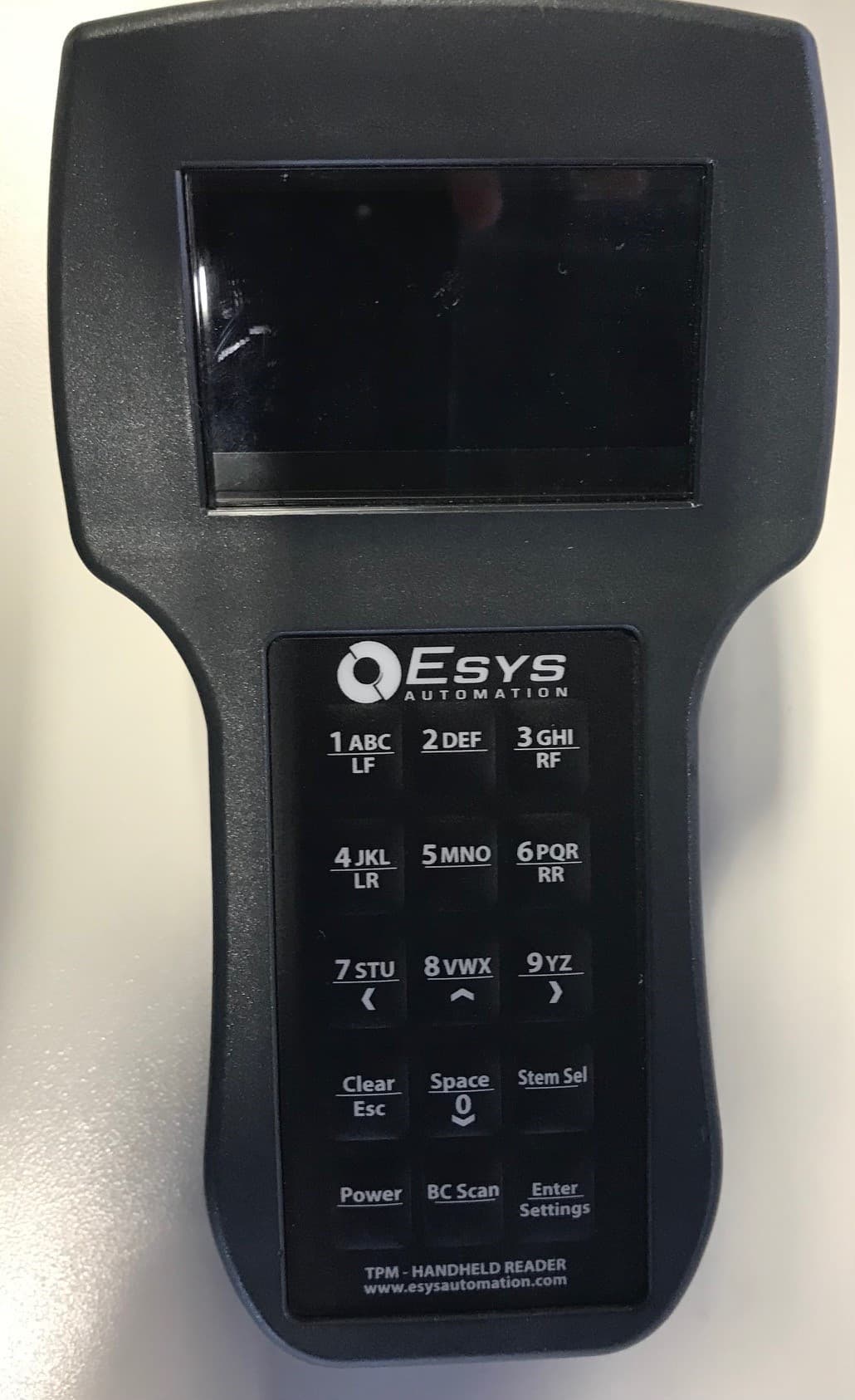
Click to zoom
Application Details
- Equipment Class
- DCD - Part 15 Low Power Transmitter Below 1705 kHz
- Date of Grant
- Nov 17, 2022
- Application Purpose
- Original Equipment
- Date of Application
- Nov 16, 2022
- Equipment Note
- Tire Pressure Monitor Handheld
- Frequency Range
- 0.12500000 - 0.12500000
- Company
- Esys Automation, LLC
- Country
- United States
Documents & Files
Document Text
Text extracted from the exhibit documents filed with the FCC. Open a document above to read the original.
Users Manual
1000 Brown Rd. Auburn Hills, MI 48326 248.754.1900 Jrautomation.com TPM Handheld User Manual - prelim 2 Page 1 of 17 Printed: 11/16/22 3:38 PM TPM Handheld User Manual Model: TPM-HH-700-00 1000 Brown Rd. Auburn Hills, MI 48326 248.754.1900 Jrautomation.com TPM Handheld User Manual - prelim 2 Page 2 of 17 Printed: 11/16/22 3:38 PM Revisions Revision Date Revised By: Description Prelim 12/29/21 Mark Compton Preliminary Contents Revisions ....................................................................................................................................................... 2 Contents ........................................................................................................................................................ 2 General Information & Considerations ......................................................................................................... 3 Safety ............................................................................................................................................................ 3 Handheld Overview....................................................................................................................................... 4 Battery Save Feature ................................................................................................................................. 5 Keypad ...................................................................................................................................................... 6 Settings Menu ............................................................................................................................................... 7 Using the Handheld to Repair a Vehicle Record ......................................................................................... 11 Deleting a Record .................................................................................................................................... 15 Appendix A: Product Data Sheet ................................................................................................................ 16 Appendix B: Reader Position Sign .............................................................................................................. 16 1000 Brown Rd. Auburn Hills, MI 48326 248.754.1900 Jrautomation.com TPM Handheld User Manual - prelim 2 Page 3 of 17 Printed: 11/16/22 3:38 PM General Information & Considerations 1. This device complies with part 15 of the FCC Rules. Operation is subject to the following two conditions: (1) This device may not cause harmful interference, and (2) this device must accept any interference received, including interference that may cause undesired operation. 2. Any changes or modifications not expressly approved by the manufacturer could void the user’s authority to operate the equipment. 3. This equipment has been tested and found to comply with the limits for a Class A digital device, pursuant to part 15 of the FCC Rules. These limits are designed to provide reasonable protection against harmful interference when the equipment is operated in a commercial environment. This equipment generates, uses, and can radiate radio frequency energy and, if not installed and used in accordance with the instruction manual, may cause harmful interference to radio communications. Operation of this equipment in a residential area is likely to cause harmful interference in which case the user will be required to correct the interference at his own expense. 4. JR Automation TPM products & related equipment must be integrated into the end users manufacturing system by JR Automation, or by a JR Automation recommended automation Systems Integrator 5. JR Automation TPM products are meant for industrial manufacturing settings only. 6. JR Automation does not manufacture or provide TPM valve stems, only the equipment that is used to communicate to those stems during tire, wheel, & vehicle manufacturing. Safety 1. Only personnel who are properly trained and have adequate knowledge and skill related to this product should undertake any troubleshooting and repair. 2. This device is capable of generating electrical voltages high enough to create a shock hazard, only qualified personnel who have a technical understanding of this device should ever attempt to open the cover on this device to troubleshoot or repair. 1000 Brown Rd. Auburn Hills, MI 48326 248.754.1900 Jrautomation.com TPM Handheld User Manual - prelim 2 Page 4 of 17 Printed: 11/16/22 3:38 PM Handheld Overview The Esys TPM Handheld Reader is built specifically for the manufacturing environment. It is typically used in conjunction with our in-line TPM Antenna Systems or by itself in very low production environments. This wireless reader can update the plant system with the correct data to program the vehicle. The TPM Handheld reader is fully cordless and come in a rugged industrial case. It utilizes a powerful Low Frequency wake-up signal (125 kHz) and comes with an integrated barcode scanner for reading vehicle IDs. Multiple TPM stems (315MHz and 433 MHz) can be programmed in the same unit and read with dual receivers. The stem types can be quickly changed with a one button press. TPM data is stored for up to 50 vehicles. A docking station can be supplied for data transfer and battery charging. The handheld is typically secured to the docking station by a magnet on the back of the handheld. The docking station is typically provided by an automation System Integrator and customized to the end user’s needs. The docking station has two pins that provide 12V DC and two other pins are a RS-485 serial communication to upload the data. Typically, to communicate to a PLC, the RS-485 link can be converted to other communication protocols (e.g. Ethernet) based on the needs of the end user’s manufacturing system. This is done with a 3 rd party communication conversion device supplied by an automation System Integrator. 1000 Brown…
Text truncated - open the document above for the full version.
ID Label/Location Info
MODEL:TPM-HH-700-000 FCC ID:2A4GATPM-HH-700-000 This device complies with part 15 of the FCC Rules. Operation is subject to the following two conditions: (1) This device may not cause harmful interference, and (2) this device must accept any interference received, including interference that may cause undesired operation. MODEL:TPM-MD-300-000 FCC ID:2A4GATPM-MD-300-000 This device complies with part 15 of the FCC Rules. Operation is subject to the following two conditions: (1) This device may not cause harmful interference, and (2) this device must accept any interference received, including interference that may cause undesired operation. MODEL:TPM-CW-300-000 FCC ID:2A4GATPM-CW-300-000 This device complies with part 15 of the FCC Rules. Operation is subject to the following two conditions: (1) This device may not cause harmful interference, and (2) this device must accept any interference received, including interference that may cause undesired operation.
ID Label/Location Info
TPM Label Locations 9-26-2022 Label Dimensions: 2’’ x 0.75’’ Label for TPM-EN-900-000J: Label for TPM-HH-700-000T:
Test Report
Engineering Test Report No. 2103898-01 Report Date February 3, 2022 Manufacturer Name JR Automation Manufacturer Address 1000 Brown Rd Auburn Hills, MI 48326 Product Name Brand/Model No. Handheld Verifier, Model Number: TPM-HH-700-00 Date Received December 28, 2021 Test Dates January 17, 2022 and January 18, 2022 Specifications FCC "Code of Federal Regulations" Title 47 Part 15, Subpart C, Section 15.209 Innovation, Science, and Economic Development Canada, RSS-Gen and RSS-102 Test Facility Elite Electronic Engineering, Inc. 1516 Centre Circle, Downers Grove, IL 60515 FCC Reg. Number: 269750 IC Reg. Number: 2987A CAB Identifier: US0107 Signature Tested by Mark Longinotti Signature Approved by Raymond J. Klouda, Registered Professional Engineer of Illinois – 44894 PO Number 423749-0510 This report is for your exclusive use. Any copying or replication of this report to or for any other person or entity, or use of our name or trademark, is permitted only with our prior written permission. This report sets forth our findings solely with respect to the test samples identified herein. The results set forth in this report are not indicative or representative of the quality or characteristics of the lot from which a test sample was taken or any similar or identical product unless specifically and expressly noted. Our report includes all of the tests requested by you and the results thereof based upon the information that you provided to us. You have 60 days from date of issuance of this report to notify us of any material error or omission caused by our negligence, provided, however, that such notice shall be in writing and shall specifically address the issue you wish to raise. A failure to raise such issue within the prescribed time shall constitute your unqualified acceptance of the completeness of this report, the tests conducted and the correctness of the report contents. This report shall not be reproduced, except in full, without the written approval of Elite Electronic Engineering Inc. Elite Electronic Engineering Incorporated certifies that the information contained in this report was obtained under conditions which meet or exceed those specified in the FCC "Code of Federal Regulations" Title 47 Part 15, Subpart C, Section 15.209 and Innovation, Science, and Economic Development Canada, RSS-Gen and RSS-102 test specifications. The data presented in this test report pertains to the EUT on the test dates specified. Any electrical or mechanical modifications made to the EUT subsequent to the specified test date will serve to invalidate the data and void this certification. This report must not be used to claim product certification, approval, or endorsement by A2LA, NIST, or any agency of the Federal Government. Engineering Test Report No. 2103898-01 This report shall not be reproduced, except in full, without the written approval of Elite Electronic Engineering Inc. Page 2 of 46 Table of Contents 1. Report Revision History ............................................................................................................................ 3 2. Introduction ............................................................................................................................................... 4 3. Power Input ............................................................................................................................................... 4 4. Grounding ................................................................................................................................................. 4 5. Support Equipment ................................................................................................................................... 4 6. Interconnect Leads .................................................................................................................................... 4 7. Modifications Made to the EUT ................................................................................................................. 4 8. Modes of Operation ................................................................................................................................... 4 8.1. CW High Power ......................................................................................................................................... 4 8.2. CW Low Power ......................................................................................................................................... 4 9. Test Specifications .................................................................................................................................... 4 10. Test Plan ................................................................................................................................................... 5 11. Deviation, Additions to, or Exclusions from Test Specifications ............................................................... 5 12. Laboratory Conditions ............................................................................................................................... 5 13. Summary ................................................................................................................................................... 5 14. Sample Calculations ................................................................................................................................. 5 15. Statement of Conformity ........................................................................................................................... 6 16. Certification ............................................................................................................................................... 6 17. Photographs of EUT .................................................................................................................................. 7 18. Equipment List ........................................................…
Text truncated - open the document above for the full version.
Test Report
1516 Centre Circle, Downers Grove IL 60515 ANTENNA EXHIBIT Manufacturer Name Esys Automation, LLC Manufacturer Address 1000 Brown Rd Auburn Hills, MI 48326 Model No. TPM-LA-300-00 & TPM-SA-300-000 TPM-LA-200-000 & TPM-SA-200-000 TPM-HH-700 Specifications FCC “Code of Federal Regulations” Title 47 Part 2.1033(b)(4), 15.203, 15.212, 15.217, 15.219, 15.255 and 15.256 KDB 353028 D01 v01 f01 Industry Canada RSS-GEN Test Facility Elite Electronic Engineering, Inc. 1516 Centre Circle, Downers Grove, IL 60515 FCC Reg. Number: 269750 IC Reg. Number: 2987A CAB Identifier: US0107 Requirement All part 15 applications will need to show how the antenna gain was derived either from a manufacturer data sheet or a measurement. Where the gain of the antenna is inherently accounted for as a result of the measurement, such as field strength measurements on a part 15.249 or 15.231 device, so the gain does not necessarily need to be verified. However, enough information regarding the construction of the antenna shall be provided. Such information maybe photographs, length of wire antenna etc. The antenna gain information shall be made public (not confidential). Any proprietary information such as construction maybe stripped from the gain information report and held confidential. The main antenna information we require is the maximum gain of the antenna for the band of operation. This information must be provided as a data sheet or a measurement report. All antennas are inductive loop antennas of various lengths. 1516 Centre Circle, Downers Grove IL 60515 Small Circle antenna 40 cm Diameter. Inductive loop TPM-LA-200-000 & TPM-SA-200-000 Oval Antenna 61 cm x 92 cm inductive loop TPM-LA-200-000 & TPM-SA-200-000 1516 Centre Circle, Downers Grove IL 60515 Rectangle Antenna 140 cm x 36 cm with three inductive loops TPM-LA-300-000 & TPM-SA-300-000 Handheld 4 cm x 8 cm inductive loop TPM-HH-700
Test Setup Photos
Engineering Test Report No. 2103898-01 Page 14 of 46 Test Setup for Radiated Emissions: 100kHz to 30MHz, Horizontal Polarization Test Setup for Radiated Emissions: 150kHz to 30MHz, Vertical Polarization Engineering Test Report No. 2103898-01 Page 15 of 46 Test Setup for Radiated Emissions: 30MHz to 1GHz, Horizontal Polarization Test Setup for Spurious Emissions: 30MHz to 1GHz, Vertical Polarization
Contact Information
Applicant
Mark A Compton(Director, PMO)
Technical Contact
Esys Automation, LLCMark Compton
[email protected]2489411763
1000 Brown Rd · Auburn Hills · United States
Non-Technical Contact
Esys Automation, LLCMark Compton
[email protected]2489411763
Test Firm
Elite Electronic Engineering Inc.Kevin Halpin
Technical Specifications
| # | Rule Parts | Frequency Range | Power Output |
|---|---|---|---|
| 1 | 15C | 0.125 MHz - 0.125 MHz | - |
Other Applications from Esys Automation, LLC

2A4GATPM-CW-300-000
Nov 17, 2022Tire Pressure Monitor Continuous Antenna
Equipment Class
DCD - Part 15 Low Power Transmitter Below 1705 kHz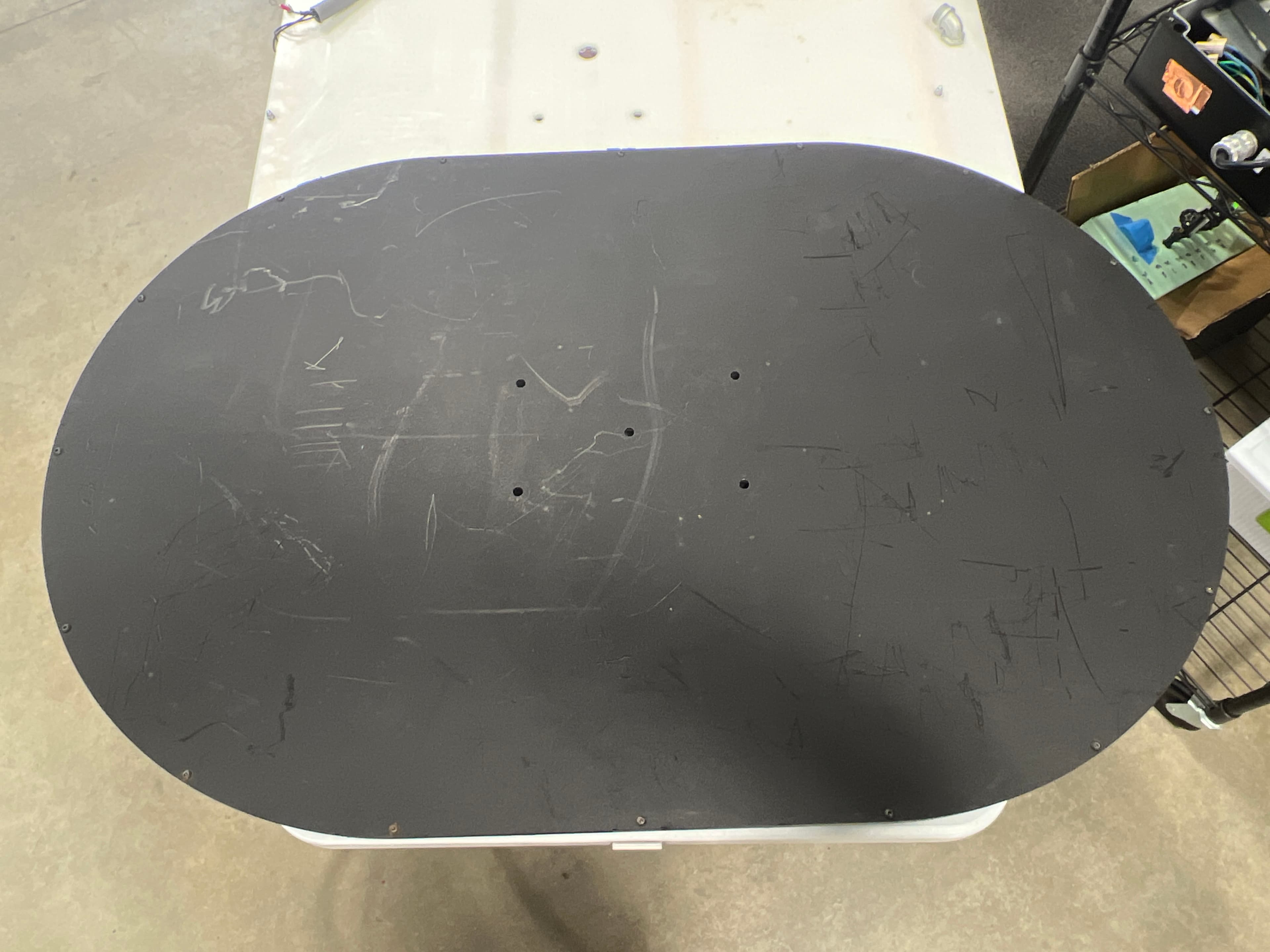
2A4GATPM-MD-200-000
Nov 17, 2022Tire Pressure Monitor Modulated Antenna
Equipment Class
DCD - Part 15 Low Power Transmitter Below 1705 kHz