2A4GATPM-MD-200-000Tire Pressure Monitor Modulated Antenna
Esys Automation, LLC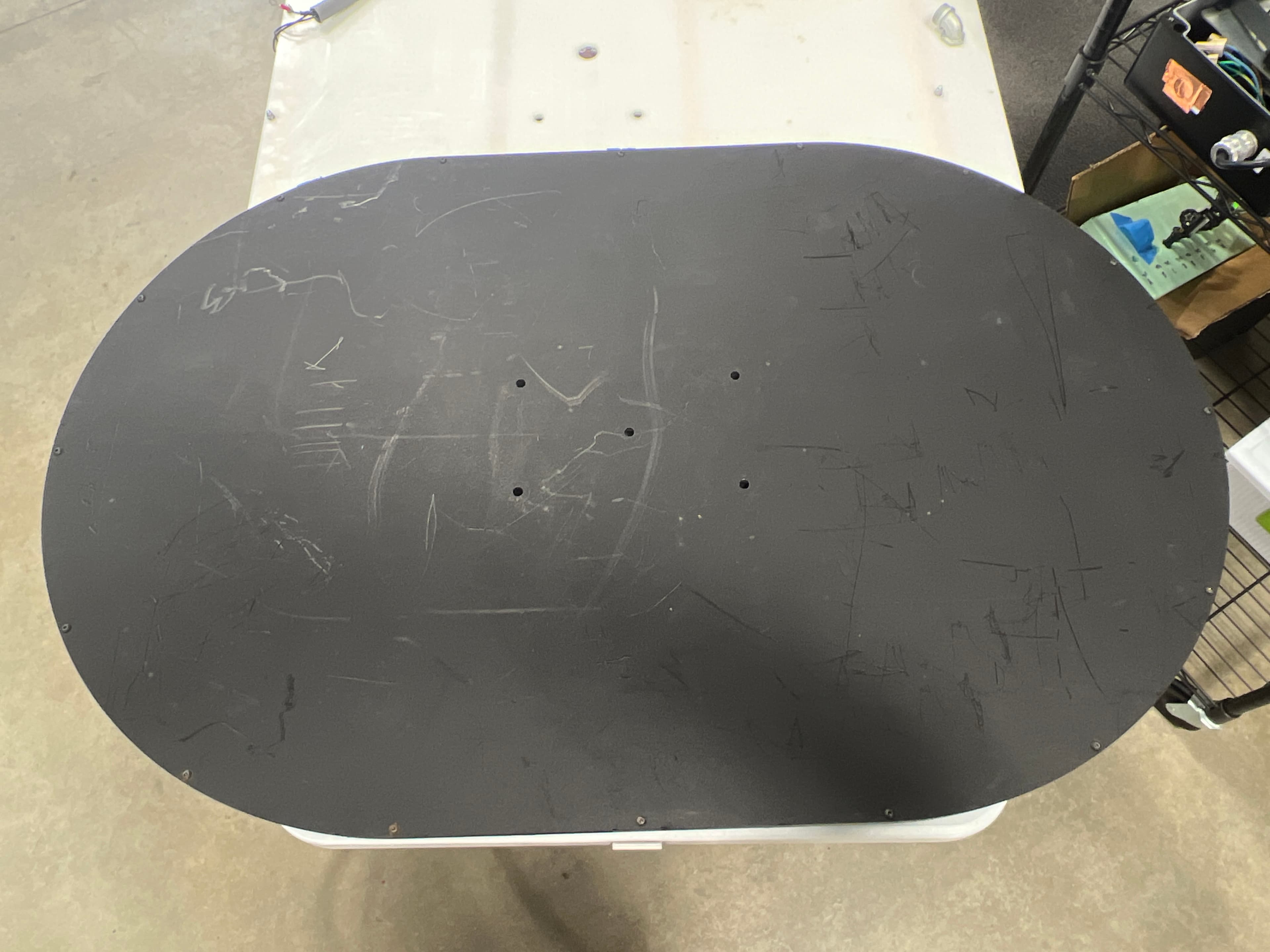
Click to zoom
Application Details
- Equipment Class
- DCD - Part 15 Low Power Transmitter Below 1705 kHz
- Date of Grant
- Nov 17, 2022
- Application Purpose
- Original Equipment
- Date of Application
- Nov 16, 2022
- Equipment Note
- Tire Pressure Monitor Modulated Antenna
- Frequency Range
- 0.12500000 - 0.12500000
- Company
- Esys Automation, LLC
- Country
- United States
Documents & Files
Document Text
Text extracted from the exhibit documents filed with the FCC. Open a document above to read the original.
Users Manual
1000 Brown Rd. Auburn Hills, MI 48326 248.754.1900 jrautomation.com Modulated Antenna User Manual - Prelim3 Page 1 of 10 Printed: 11/16/22 3:39 PM Modulated TPM Antenna User Manual Model Number: TPM-MD-200-000 Includes Variants: TPM-LA-200-000 & TPM-SA-200-000 1000 Brown Rd. Auburn Hills, MI 48326 248.754.1900 jrautomation.com Modulated Antenna User Manual - Prelim3 Page 2 of 10 Printed: 11/16/22 3:39 PM REVISIONS Revision Date Revised By: Description Prelim 12/28/21 Mark Compton Preliminary CONTENTS Modulated TPM Antenna User Manual ...................................................................................................................... 1 REVISIONS ............................................................................................................................................................... 2 CONTENTS ............................................................................................................................................................... 2 GENERAL INFORMATION........................................................................................................................................ 3 SAFETY ..................................................................................................................................................................... 3 PERSONAL PROTECTIVE EQUIPMENT ................................................................................................................. 4 GROUNDING ............................................................................................................................................................. 4 ELECTRICAL WARNING SIGNS .............................................................................................................................. 4 TPM STEM OVERVIEW ............................................................................................................................................ 5 LF TRANSMISSION (125KHz) .................................................................................................................................. 6 RECEIVING UHF SIGNALS ...................................................................................................................................... 7 EXTERNAL CONNECTIONS & LED INDICATORS ................................................................................................. 8 ANTENNA MOUNTING ............................................................................................................................................. 9 APPENDIX A: PRODUCT DATA SHEET ............................................................................................................... 10 1000 Brown Rd. Auburn Hills, MI 48326 248.754.1900 jrautomation.com Modulated Antenna User Manual - Prelim3 Page 3 of 10 Printed: 11/16/22 3:39 PM GENERAL INFORMATION 1. This device complies with part 15 of the FCC Rules. Operation is subject to the following two conditions: (1) This device may not cause harmful interference, and (2) this device must accept any interference received, including interference that may cause undesired operation. 2. Any changes or modifications not expressly approved by the manufacturer could void the user’s authority to operate the equipment. 3. This equipment has been tested and found to comply with the limits for a Class A digital device, pursuant to part 15 of the FCC Rules. These limits are designed to provide reasonable protection against harmful interference when the equipment is operated in a commercial environment. This equipment generates, uses, and can radiate radio frequency energy and, if not installed and used in accordance with the instruction manual, may cause harmful interference to radio communications. Operation of this equipment in a residential area is likely to cause harmful interference in which case the user will be required to correct the interference at his own expense. 4. JR Automation TPM products & related equipment must be integrated into the end users manufacturing system by JR Automation, or by a JR Automation recommended automation Systems Integrator 5. JR Automation TPM products are meant for industrial manufacturing settings only. 6. JR Automation does not manufacture or provide TPM valve stems, only the equipment that is used to communicate to those stems during tire, wheel, & vehicle manufacturing. SAFETY 1. The device shall be used in such a manner that the potential for human contact normal operation is minimized. This equipment complies with FCC radiation exposure limits set forth for an uncontrolled environment. This equipment should be installed and operated with a minimum distance of 30cm between the radiator and your body. This device and its antenna(s) must not be co-located or operating in conjunction with any other antenna or transmitter. 2. Only personnel who are properly trained and have adequate knowledge and skill related to this product should undertake any troubleshooting and repair. 3. It must be assumed at all times that POWER is "ON" so all conditions must be treated as live. This practice develops a caution that may prevent an accident. Follow posted lockout procedures. 4. REMOVE LOAD from circuit or equipment before and after maintenance/troubleshooting. 5. Equipment—NOTE: Test equipment must be checked at regular intervals. 6. Capacitors MUST be given time to discharge, otherwise it should be done manually with CARE. 7. When troubleshooting "LIVE" equipment, the necessary precautions must be taken as follows: a. Follow written safe operating practices. b. MAKE CERTAIN your tools and body are clear of Ground. c. Use extra PRECAUTION in DAMP areas. d. BE ALERT and work without any outside distraction. 8. BEFORE applying POWER to any equipment, it must be established without a DOUBT that all persons are CLEAR. 9. Any CONTROL PANEL DOORS shall be open ONLY when it is necessary to check out the electrical equipment or wiring. Aft…
Text truncated - open the document above for the full version.
ID Label/Location Info
MODEL:TPM-MD-200-000 FCC ID:2A4GATPM-MD-200-000 This device complies with part 15 of the FCC Rules. Operation is subject to the following two conditions: (1) This device may not cause harmful interference, and (2) this device must accept any interference received, including interference that may cause undesired operation.
ID Label/Location Info
TPM Label Locations 9-26-2022 Label Dimensions: 2’’ x 0.75’’ Label for TPM-EN-900-000J: Label for TPM-HH-700-000T:
Test Report
1516 Centre Circle, Downers Grove IL 60515 ANTENNA EXHIBIT Manufacturer Name Esys Automation, LLC Manufacturer Address 1000 Brown Rd Auburn Hills, MI 48326 Model No. TPM-LA-300-00 & TPM-SA-300-000 TPM-LA-200-000 & TPM-SA-200-000 TPM-HH-700 Specifications FCC “Code of Federal Regulations” Title 47 Part 2.1033(b)(4), 15.203, 15.212, 15.217, 15.219, 15.255 and 15.256 KDB 353028 D01 v01 f01 Industry Canada RSS-GEN Test Facility Elite Electronic Engineering, Inc. 1516 Centre Circle, Downers Grove, IL 60515 FCC Reg. Number: 269750 IC Reg. Number: 2987A CAB Identifier: US0107 Requirement All part 15 applications will need to show how the antenna gain was derived either from a manufacturer data sheet or a measurement. Where the gain of the antenna is inherently accounted for as a result of the measurement, such as field strength measurements on a part 15.249 or 15.231 device, so the gain does not necessarily need to be verified. However, enough information regarding the construction of the antenna shall be provided. Such information maybe photographs, length of wire antenna etc. The antenna gain information shall be made public (not confidential). Any proprietary information such as construction maybe stripped from the gain information report and held confidential. The main antenna information we require is the maximum gain of the antenna for the band of operation. This information must be provided as a data sheet or a measurement report. All antennas are inductive loop antennas of various lengths. 1516 Centre Circle, Downers Grove IL 60515 Small Circle antenna 40 cm Diameter. Inductive loop TPM-LA-200-000 & TPM-SA-200-000 Oval Antenna 61 cm x 92 cm inductive loop TPM-LA-200-000 & TPM-SA-200-000 1516 Centre Circle, Downers Grove IL 60515 Rectangle Antenna 140 cm x 36 cm with three inductive loops TPM-LA-300-000 & TPM-SA-300-000 Handheld 4 cm x 8 cm inductive loop TPM-HH-700
Test Report
Authors: Cullen Davison Warren Guthrie Isaiah Hendrick Date: Procedure: 1 - Measure worst-case field on all sides of the DUT, except for the front side.Equipment: The front side is known to be the worst-case magnetic field, as the sides and back have shielding.Wavecontrol E/H Probe Model WP400-3 S/N 22WP120108 Apply duty cycle-averaging over appropriate time (30 minutes) to each side and back measurement.WaveControl Field Meter SMP2 S/N 22SN1853 2 - Mark out a grid (See picture) Mark out 2.5 inch grid squares Approximately 18 inches below product Up to 1.5 meters from bottom edge to top of grid 3 - Measure the H field at each grid position (27 cm from surface in order to fall within limit) 4 - RMS average the field Over a range of approximately 1 meter wide and 1.8 meters tall Sweep the range over the entire grid range (unil the range starts to leave the grid) Find worst-case spatially-averaged field measurement and apply step 4. 5 - Apply duty cycle averaging over appropriate time (30 minutes) Step 1 - Measure worst-case field on all other sides of the DUT. Product duty cycle: Right side (3cm from surface):Left side (3cm from surface):Bottom side:Top side (3cm from surface):Back side: Worst case magnetic field:Worst case magnetic field:Worst case magnetic field:Worst case magnetic field:Worst case magnetic field: μTμTμTμTμT Apply duty cycle averaging:Apply duty cycle averaging:Apply duty cycle averaging:Apply duty cycle averaging:Apply duty cycle averaging: μT→μT→μT→μT→μT→ Product Perimeter Step 3: Measure at each grid location (27 cm from surface)Step 2: Marked out grid Picture of the grid used, along with the DUT. 0.2 0.2 0.2 0.2 0.2 0.2 0.2 0.2 0.2 0.2 0.2 0.2 0.2 0.2 0.2 0.2 0.2 0.2 0.2 0.2 0.2 0.2 0.2 0.2 0.2 0.2 0.2 0.2 0.2 0.2 0.2 0.2 0.2 0.2 0.2 0.2 0.2 0.2 0.2 0.2 0.2 0.2 0.2 0.2 0.2 0.2 0.2 0.2 0.2 0.2 0.2 0.2 0.2 0.2 0.2 0.2 0.2 0.2 0.2 0.2 0.2 0.2 0.2 0.2 0.2 0.2 0.2 0.2 0.2 0.2 0.2 0.2 0.2 0.2 0.2 0.2 0.2 0.2 0.2 0.2 0.2 0.2 0.2 0.2 0.2 0.2 0.2 0.2 0.2 0.2 0.2 0.2 0.2 0.2 0.2 0.2 0.2 0.2 0.2 0.2 0.2 0.2 0.2 0.2 0.2 0.2 0.2 0.2 0.2 0.2 0.2 0.2 0.2 0.2 0.2 0.2 0.2 0.2 0.2 0.2 0.2 0.2 0.2 0.2 0.2 0.2 0.2 0.2 0.2 0.2 0.2 0.2 0.2 0.2 0.2 0.2 0.2 0.2 0.2 0.2 0.2 0.2 0.2 0.2 0.2 0.2 0.2 0.2 0.2 0.2 0.2 0.2 0.2 0.2 0.2 0.2 0.2 0.2 0.2 0.2 0.2 0.2 0.2 0.2 0.2 0.2 0.2 0.2 0.2 0.2 0.2 0.2 0.2 0.2 0.2 0.2 0.2 0.2 0.2 0.2 0.2 0.2 0.2 0.2 0.2 0.2 0.2 0.2 0.2 0.2 0.2 0.2 0.2 0.2 0.2 0.2 0.2 0.2 0.2 0.2 0.2 0.2 0.2 0.2 0.2 0.2 0.2 0.2 0.2 0.2 0.2 0.2 0.2 0.2 0.2 0.2 0.2 0.2 0.2 0.2 0.2 0.2 0.2 0.2 0.2 0.2 0.2 0.2 0.2 0.2 0.2 0.2 0.2 0.2 0.2 0.2 0.2 0.2 0.2 0.2 0.2 0.2 0.2 0.2 0.2 0.2 0.2 0.2 0.2 0.2 0.2 0.2 0.2 0.2 0.2 0.2 0.2 0.2 0.2 0.2 0.2 0.2 0.2 0.2 0.2 0.2 0.2 0.2 0.2 0.2 0.2 0.2 0.2 0.2 0.2 0.2 0.2 0.2 0.2 0.2 0.2 0.2 0.2 0.2 0.2 0.2 0.2 0.2 0.2 0.2 0.2 0.2 0.2 0.2 0.2 0.2 0.2 0.2 0.2 0.2 0.2 0.2 0.2 0.2 0.2 0.2 0.2 0.2 0.2 0.2 0.2 0.2 0.2 0.2 0.2 0.2 0.2 0.2 0.2 0.2 0.2 0.2 0.2 0.2 0.2 0.2 0.2 0.2 0.2 0.2 0.2 0.2 0.2 0.2 0.2 0.2 0.2 0.2 0.2 0.2 0.2 0.2 0.2 0.2 0.2 0.2 0.2 0.2 0.2 0.2 0.2 0.2 0.2 0.2 0.2 0.2 0.2 0.2 0.2 0.2 0.2 0.2 0.2 0.2 0.2 0.2 0.2 0.2 0.2 0.2 0.2 0.2 0.2 0.2 0.2 0.2 0.2 0.2 0.2 0.2 0.2 0.2 0.2 0.2 0.2 0.2 0.2 0.2 0.2 0.2 0.2 0.2 0.2 0.2 0.2 0.2 0.2 0.2 0.2 0.2 0.2 0.2 0.2 0.2 0.2 0.2 0.2 0.2 0.2 0.2 0.2 0.2 0.2 0.2 0.2 0.2 0.2 0.2 0.2 0.2 0.2 0.2 0.2 0.2 0.2 0.2 0.2 0.2 0.2 0.2 0.2 0.2 0.2 0.2 0.2 0.2 0.2 0.2 0.2 0.2 0.2 0.2 0.2 0.2 0.2 0.2 0.2 0.2 0.2 0.2 0.2 0.2 0.2 0.2 0.2 0.2 0.2 0.2 0.2 0.2 0.2 0.2 0.2 0.2 0.2 0.2 0.2 0.2 0.2 0.2 0.2 0.2 0.2 0.2 0.2 0.2 0.2 0.2 0.2 0.2 0.2 0.2 0.2 0.2 0.2 0.2 0.2 0.2 0.2 0.2 0.2 0.2 0.2 0.2 0.2 0.2 0.2 0.2 0.2 0.2 0.2 0.2 0.2 0.2 0.2 0.2 0.2 0.2 0.2 0.2 0.2 0.2 0.2 0.2 0.2 0.2 0.2 0.2 0.2 0.2 0.2 0.2 0.2 0.2 0.2 0.2 0.2 0.2 0.2 0.2 0.2 0.2 0.2 0.2 0.2 0.2 0.2 0.2 0.2 0.2 0.2 0.2 0.2 0.2 0.2 0.2 0.2 0.2 0.2 0.2 0.2 0.2 0.2 0.2 0.2 0.2 0.2 0.2 0.2 0.2 0.2 0.2 0.2 0.2 0.2 0.2 0.2 0.2 0.2 0.2 0.2 0.2 0.2 0.2 0.2 0.2 0.2 0.2 0.2 0.2 0.2 0.2 0.2 0.2 0.2 0.2 0.2 0.2 0.2 0.2 0.2 0.2 0.2 0.2 0.2 0.2 0.2 0.2 0.2 0.2 0.2 0.2 0.2 0.2 0.2 0.2 0.2 0.2 0.2 0.2 0.2 0.2 0.2 0.2 0.2 0.2 0.2 0.2 0.2 0.2 0.2 0.2 0.2 0.2 0.2 0.2 0.2 0.2 0.2 0.2 0.2 0.2 0.2 0.2 0.2 0.3 0.3 0.3 0.3 0.3 0.2 0.2 0.2 0.2 0.2 0.2 0.2 0.2 0.2 0.2 0.2 0.2 0.2 0.2 0.2 0.2 0.2 0.2 0.2 0.2 0.2 0.2 0.2 0.2 0.2 0.2 0.2 0.2 0.2 0.2 0.2 0.2 0.2 0.2 0.2 0.2 0.2 0.2 0.2 0.2 0.2 0.2 0.2 0.3 0.3 0.3 0.3 0.3 0.3 0.3 0.3 0.3 0.3 0.3 0.2 0.2 0.2 0.2 0.2 0.2 0.2 0.2 0.2 0.2 0.2 0.2 0.2 0.2 0.2 0.2 0.2 0.2 0.2 0.2 0.2 0.2 0.2 0.2 0.2 0.2 0.2 0.2 0.2 0.2 0.2 0.2 0.2 0.2 0.2 0.2 0.2 0.2 0.3 0.3 0.3 0.4 0.4 0.4 0.4 0.5 0.5 0.4 0.4 0.4 0.3 0.3 0.2 0.2 0.2 0.2 0.2 0.2 0.2 0.2 0.2 0.2 0.2 0.2 0.2 0.2 0.2 0.2 0.2 0.2 0.2 0.2 0.2 0.2 0.2 0.2 0.2 0.2 0.2 0.2 0.2 0.2 0.2 0.2 0.2 0.2 0.2 0.3 0.3 0.3 0.4 0.4 0.5 0.6 0.6 0.6 0.6 0.6 0.6 0.6 0.5 0.4 0.4 0.3 0.3 0.2 0.2 0.2 0.2 0.2 0.2 0.2 0.2 0.2 0.2 0.2 0.2 0.2 0.2 0.2 0.2 0.2 0.2 0.2 0.2 0.2 0.2 0.2 0.2 0.2 0.2 0.2 0.2 0.2 0.2 0.2 0.2 0.2 0.3 0.3 0.4 0.5 0.6 0.7 0.7 0.8 0.9 0.9 0.9 0.9 0.8 0.6 0.5 0.4 0.4 0.3 0.3 0.2 0.2 0.2 0.2 0.2 0.2 0.2 0.2 0.2 0.2 0.2 0.2 0.2 0.2 0.2 0.2 0.2 0.2 0.2 0.2 0.2 0.2 0.2 0.2 0.2 0.2 0.2 0.2 0.2 0.2 0.2 0.3 0.3 0.4 0.5 0.6 0.8 0.9 1.1 1.2 1.4 1.4 1.4 1.3 1.2 0.9 0.8 0.6 0.5 0.4 0.3 0.3 0.2 0.2 0.2 0.2 0.2 0.2 0.2 0.2 0.2 0.2 0.2 0.2 0.2 0.2 0.2 0.2 0.2 0.2 0.2 0.2 0.2 0.2 0.2 0.2 0.2 0.2 0.2 0.2 0.2 0.3 0.3 0.4 0.6 0.7 0.9 1.2 1.4 1.8 2.1 2.2 2.3 2.2 2.1 1.9 1.5 1.2 0.9 0.7 0.5 0.4 0.3 0.3 0.2 0.2 0.2 0.2 0.2 0.2 0.2 0.2 0.2 0.2 0.2 0.2 0.2 0.2 0.2 0.2 0.2 0.2 0.2 0.2 0.2 0.2 0.2 0.2 0.2 0.2 0.2 0.2 0.3 0.3 0.5 0.7 0.9 1.3 1.7 2.1 2.6 3.0 3.2 3.4 3.3 3.1 2.6 2.1 1.7 1.3 1.0 0.7 0.5 0.4 0.3 0.2 0.2 0.2 0.2 0.2 0.2 0.2 0.2 0.2 0.2 0.2 0.2 0.2 0.2 0.2 0.2 0.2 0.2 0.2 0.2 0.2 0.2 0.2 0.2 0.2 0.2 0.2 0.3 0.3 0.4 0.6 0.8 1.2 1.6 2.2 2.7 3.3 3.8 4.2 4.3 4.2 3.9 3.4 2.8 2.2 1.7 1.2 0.8 0.6 0.4 0.3 0.3 0.2 0.2 0.2 0.2 0.2 0.2 0.2 0.2 0.2 0.2 0.2 0.2 0.2 0.2 0.2 0.2 0.2 0.2 0.2 0.2 0.2 0.2 0.2 0.2 0.2 0.2 0.3 0.4 0.5 0.7 1.0…
Text truncated - open the document above for the full version.
Test Setup Photos
Engineering Test Report No. 2103900-01 Page 14 of 92 Test Setup for Radiated Spurious Emissions – 150kHz – 30MHz X-Axis Polarization Test Setup for Radiated Spurious Emissions – 150kHz – 30MHz Y-Axis Polarization Engineering Test Report No. 2103900-01 Page 15 of 92 Test Setup for Radiated Spurious Emissions – 150kHz – 30MHz Z-Axis Polarization
Contact Information
Applicant
Mark A Compton(Director, PMO)
Technical Contact
Esys Automation, LLCMark Compton
[email protected]2489411763
1000 Brown Rd · Auburn Hills · United States
Non-Technical Contact
Esys Automation, LLCMark Compton
[email protected]2489411763
Test Firm
Elite Electronic Engineering Inc.Kevin Halpin
Technical Specifications
| # | Rule Parts | Frequency Range | Power Output |
|---|---|---|---|
| 1 | 15C | 0.125 MHz - 0.125 MHz | - |
Other Applications from Esys Automation, LLC
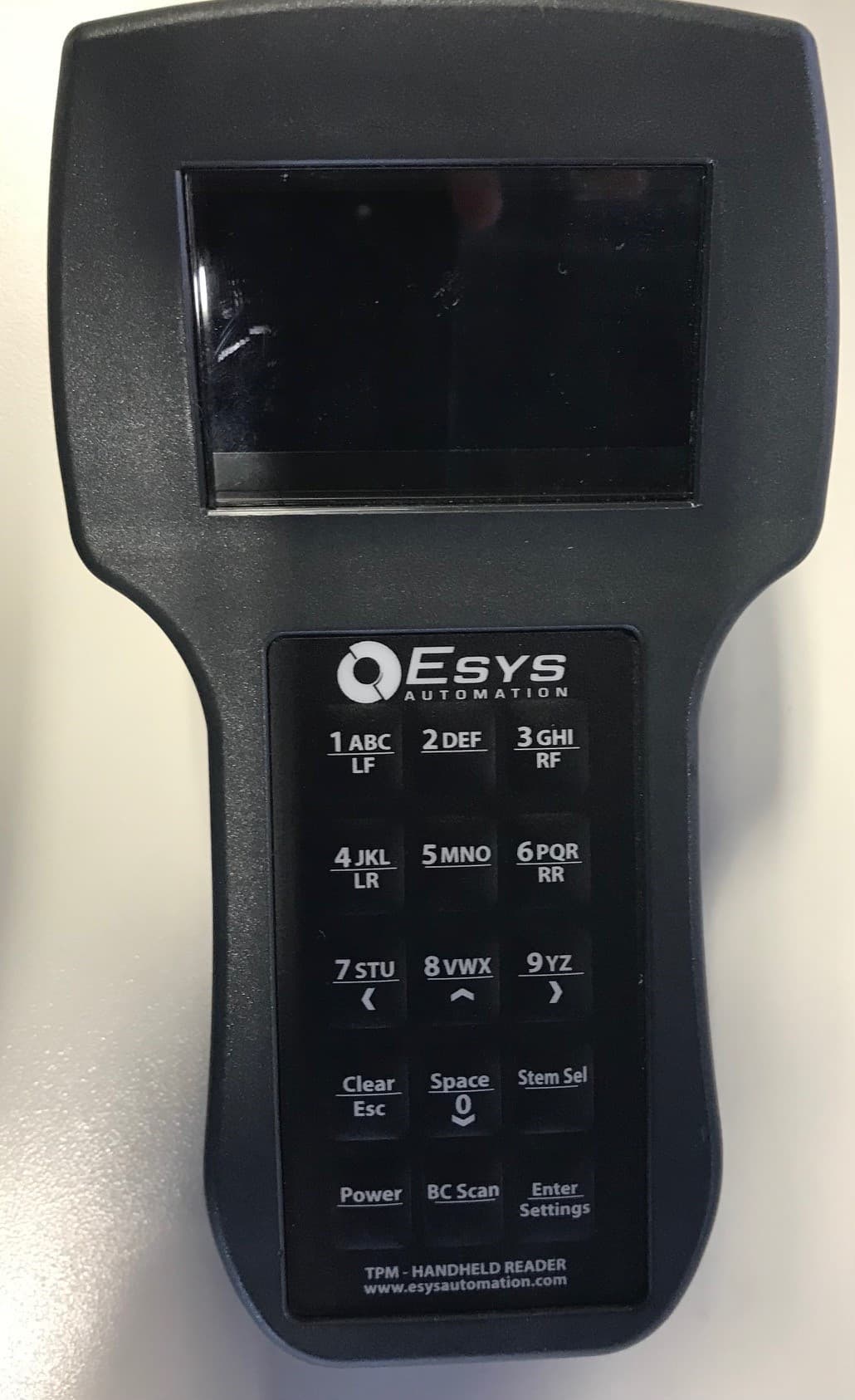
2A4GATPM-HH-700-000
Nov 17, 2022Tire Pressure Monitor Handheld
Equipment Class
DCD - Part 15 Low Power Transmitter Below 1705 kHz
2A4GATPM-CW-300-000
Nov 17, 2022Tire Pressure Monitor Continuous Antenna
Equipment Class
DCD - Part 15 Low Power Transmitter Below 1705 kHz