2A4UH-SRT1HI-FI DAC MUSIC STREAM MODULE
Santos Electronics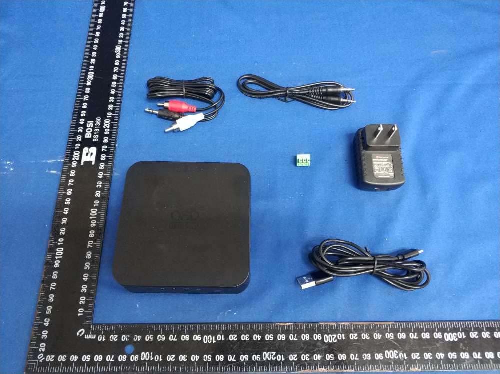
Click to zoom
Application Details
- Equipment Class
- DTS - Digital Transmission System
- Date of Grant
- Apr 24, 2022
- Application Purpose
- Original Equipment
- Date of Application
- Apr 24, 2022
- Equipment Note
- HI-FI DAC MUSIC STREAM MODULE
- Frequency Range
- 2422.00000000 - 2452.00000000
- Company
- Santos Electronics
- Country
- United States
Documents & Files
Document Text
Text extracted from the exhibit documents filed with the FCC. Open a document above to read the original.
Users Manual
QUICK START SRT1 SRT1 MANUAL.indd 17/16/19 11:32 AM 3 • The product should not be exposed to any dripping or splashing liquid. oduct. • Keep the remote control battery away from children. Dispose of used battery promptly, replace only with a battery of the correct type. • Protect the power cord from damage. Do not pull push the power cord excessively, and take care not to let the power cord become pinched, particularly at or near the plug. • Keep the product away from heat sources such as heat registers, stoves or other appliances that produce heat. • Avoid direct sunshine. Do not operate in a sealed box. • Do not open the cover, or touch the inner parts, refer servicing to our customer service. SAFETY INSTRUCTIONSFEATURES 1. Line Indicator 2. Bluetooth ® Indicator 3. Wi-Fi ® Indicator 4. TF Card Indicator 5. IR receiving window 6. Optical Output 7. Line In 8. Line Out 9. LAN Input 10. RS232 11. WPS 12. 5V DC In 13. TF Card Port 115mm 115mm OPTICAL OUT WPSLINE OUT LINE IN LAN TF RS-232 54321 13 6 7 8 9101112 115mm SRT1 MANUAL.indd 2-37/16/19 11:32 AM TF FCC ID: 2A4UH-SRT1 5 1. On/Off Button 2. WiFi ® Source 3. Volume Up 4. Volume Down 5. Next Track 6. Previous Track 7. TF Source 8. Play All Source 9. Line Source 10. Play/Pause 11. Bluetooth ® Source REMOTE FEATURES Wi-Fi ® Connection: 1. Download and install the OSD Player App for your iOS or Android device. 2. Press the Wi-Fi ® button on the remote to activate the Wi-Fi source. 3. WPS: - Link your device to the SRT1 and your Wi-Fi network by following the setup steps in the app. Get The OSD Player App: 1. Connect the power cord to the back of the SRT1 then connect it to a wall outlet. 2. Connect your devices to a suitable input 3. Press the Bluetooth ® , OPT, LINE or AUX button on the remote or the volume knob to choose a audio source. Control the playback via the remote control by pressing the buttons. Note: Always press the desired source button on the remote control for the audio source to work. Connect Your Device: Connect your CD/phone/tablet/MP3 etc... via the appropriate cable your device is compatible with to one of the source inputs on the back of the SRT1. Bluetooth ® Pairing: 1. Press the Bluetooth ® on the remote to activate the Bluetooth source. 2. Activate Bluetooth on your phone/tablet and start searching for new Bluetooth devices. 3. When your phone/tablet finds SRT1, choose this unit and begin pairing. 4. To unpair an existing source, press and hold the Bluetooth button on the remote for 3 seconds. SETUP SRT1 MANUAL.indd 4-57/16/19 11:32 AM 7 PROBLEMPOSSIBLE CAUSE No Power- The power cord is disconnected. - Poor connection at the wall socket or the wall socket is inactive. No Sound- Volume control at lowest level. - Check if the signal cables are damaged. - Check if the LEDs are blinking. If not, re start the unit and ensure that the LED displays is in standby. If it still doesn’t work, contact customers service. Sudden Sound Loss- Check the audio source. Poor Sound Quality- Audio source problem - Bad or incorrect speakers connections. - Treble and bass control are too low. LED Off- Check if the unit is connected with the power outlet SPECIFICATIONS TROUBLE SHOOTIN G The Bluetooth® word mark and logos are registered trademarks owned by Bluetooth SIG, Inc. and any use of such marks by OSD BLACK is under license. Other trademarks and trade names are those of their respective owners. Inputs: Wi-Fi ® , Bluetooth ® , LAN, TF, 3.5mm Output: 3.5mm Headphone Jack, Optical DAC: Cirrus Logic CS8406 24 Bit/192kHz DAC Wi-Fi Frequency: 2.4 GHz Bluetooth Version: 4.2 V/ aptX™ Dimensions: 4.5 x 4.5 x 1.18” inch All OSD BLACK electronics have (2) year Limited Warranty against defects in materials and workmanship. Proof of purchase must accompany all claims. During the warranty period OSD BLACK will replace any defective part and correct any defect in workmanship without charge for either parts or labor. OSD BLACK may replace returned electronics with a product of equal value and performance. In such cases, some Damage to or destruction of components due to application of excessive power voids the warranty on those parts. In these cases, repairs will be made on the basis of the retail value of the parts and labor. T o return for repairs, you must email customer service at [email protected] for a Returned Merchandise Authorization (RMA) number then the unit must be shipped to OSD BLACK at the owner’s expense, along with a note explaining the nature of service required. Be sure to pack the product(s) in a corrugated container with at least 3 inches of resilient material to protect the unit from damage in transit. This Warranty Does Not Cover: Damage caused by abuse, accident, misuse, negligence, or improper operation (installation). altered, defaced or removed. Normal wear and maintenance. SRT1 MANUAL.indd 6-77/16/19 11:32 AM Any Changes or modifications not expressly approved by the party responsible for compliance could void the user's authority to operate the equipment. Note: This equipment has been tested and found to comply with the limits for a Class B digital device, pursuant to part 15 of the FCC Rules. These limits are designed to provide reasonable protection against harmful interference in a residential installation. This equipment generates uses and can radiate radio frequency energy and, if not installed and used in accordance with the instructions, may cause harmful interference to radio communications. However, there is no guarantee that interference will not occur in a particular installation. If this equipment does cause harmful interference to radio or television reception, which can be determined by turning the equipment off and on, the user is encouraged to try to correct the interference by one or more of the following measures: -Reorient or relocate the receiving antenna. -Increase the separation between the equipment and receiver. -Connect the equipment into an outlet on a circuit different from that to which t…
Text truncated - open the document above for the full version.
External Photos
FCC ID: 2A4UH-SRT1 . FCC ID: 2A4UH-SRT1 FCC ID: 2A4UH-SRT1 FCC ID: 2A4UH-SRT1
Internal Photos
FCC ID: 2A4UH-SRT1 FCC ID: 2A4UH-SRT1 BTAnt FCC ID: 2A4UH-SRT1 FCC ID: 2A4UH-SRT1 FCC ID: 2A4UH-SRT1 FCC ID: 2A4UH-SRT1 WIFI Antenna FCC ID: 2A4UH-SRT1
RF Exposure Info
RF Exposure evaluation Exposure category: General population/uncontrolled environment EUT Type: Production Unit Device Type: Mobile Device Refer Standard: KDB 447498 D01 General RF Exposure Guidance v06 FCC Part 2 §2.1091 FCC ID: 2A4UH-SRT1 1. Applicable Standard According to §1.1307(b)(1), systems operating underthe provisions of this section shall be operated in a manner that ensures that the public is not exposed to radio frequency energy level in excess of the Commission’s guidelines. According to §1.1310 and §2.1093 RF exposure requirement KDB447498 v06: Mobile and Portable Devices RF Exposure Procedures and Equipment Authorization Policies. 2. Requirement According to KDB447498 D01 General RF Exposure Guidance v06 Section 4.3.1 Standalone SAR test exclusion considerations: “Unless specifically required by the published RF exposure KDB procedures, standalone 1-g head or body and 10-g extremity SAR evaluation for general population exposure conditions, by measurement or numerical simulation, is not required when the corresponding SAR Test Exclusion Threshold condition, listed below, is satisfied. These test exclusion conditions are based on source-based time-averaged maximum conducted output power of the RF channel requiring evaluation, adjusted for tune-up tolerance, and the minimum test separation distance required for the exposure conditions.22 The minimum test separation distance is determined by the smallestdistance from the antenna and radiating structures or outer surface of the device, according to the host form factor, exposure conditions and platform requirements, to any part of the body or extremity of a user or bystander (see 5) of section 4.1). To qualify for SAR test exclusion, the test separation distances applied must be fully explained and justified by the operating configurations and exposure conditions of the transmitter and applicable host platform requirements, typically in the SAR measurement or SAR analysis report, according to the required published RF exposure KDB procedures. When no other RF exposure testing or reporting is required, a statement of justification and compliance must be included in the equipment approval, in lieu of the SAR report, to qualify for the SAR test exclusion. When required, the device specific conditions described in the other published RF exposure KDB procedures must be satisfied before applying these SAR test exclusion provisions; for example, handheld PTT two-way radios, handsets, laptops & tablets etc.23 “ [(max. power of channel, including tune-up tolerance, mW)/ (min. test separation distance, mm)] · [√f(GHz)] ≤ 3.0 for 1-g SAR and ≤ 7.5 for 10-g extremity SAR, where: • f (GHz) is the RF channel transmit frequency in GHz • Power and distance are rounded to the nearest mW and mm before calculation • The result is rounded to one decimal place for comparison • 3.0 and 7.5 are referred to as the numeric thresholds in the step 2 below The test exclusions are applicable only when the minimum test separation distance is ≤ 50 mm and for transmission frequencies between 100 MHz and 6 GHz. When the minimum test separation distance is < 5 mm,adistanceof5mmaccordingto5)insection4.1isappliedtodetermineSARtestexclusion. 3. Limit Limits for Maximum Permissible Exposure (MPE)/Controlled Exposure Frequency Range(MHz) Electric Field Strength(V/m) Magnetic Field Strength(A/m) Power Density (mW/cm²) Averaging Time (minute) Limits fo rOccupational/Controlled Exposure 0.3 – 3.0 3.0 – 30 30 – 300 300 – 1500 1500 – 100,000 614 1842/f 61.4 / / 1.63 4.89/f 0.163 / / (100) * (900/f 2 )* 1.0 f/300 5 6 6 6 6 6 Limits for Maximum Permissible Exposure (MPE)/Uncontrolled Exposure Frequency Range(MHz) Electric Field Strength(V/m) Magnetic Field Strength(A/m) Power Density (mW/cm²) Averaging Time (minute) Limits fo rOccupational/Controlled Exposure 0.3 – 3.0 3.0 – 30 30 – 300 300 – 1500 1500 – 100,000 614 824/f 27.5 / / 1.63 2.19/f 0.073 / / (100) * (180/f 2 )* 0.2 f/1500 1.0 30 30 30 30 30 F=frequency in MHz *=Plane-wave equivalent power density 4. MPE Calculation Method Predication of MPE limit at a given distance Equation from page 18 of OET Bulletin 65, Edition 97-01 S=PG/4πR² Where: S=power density P=power input to antenna G=power gain of the antenna in the direction of interest relative to an isotropic radiator R=distance to the center of radiation of the antenna As declared by the Applicant, the EUT transmits with the maximum soure-baed Duty Cycle of 100%-see the User manual, and the EUT is a wireless device used in a mobile application, at least 20 cm from any body part of the user or nearby persons; from the maximum EUT RF output power, the minimum mobile separation distance, r =20cm, as well as the gain of the used antenna is 2.15dBi for WLAN, and the power drift from Turn-up Procedure provide by manufacturer as following states, the RF power density can be obtained. 5.Antenna Information use antennas certificated as follows provided by manufacturer; Internal Identification Antenna Identification in Internal photos Antenna type and antenna number Operate frequency band Maximum antenna gain 2.4GWIFIAntenna BInternal Antenna2400-2500MHz2.15dBi BTAntenna AInternal Antenna2400-2500MHz0dBi 6. Manufacturing Tolerance BT GFSK(Peak) ChannelChannel 00Channel 39Channel 78 Target (dBm)3.03.03.0 Tolerance ±(dB)1.01.01.0 BTπ/4 DQPSK(Peak) ChannelChannel 00Channel 39Channel 78 Target (dBm)3.03.03.0 Tolerance ±(dB)1.01.01.0 BT 8DPSK(Peak) ChannelChannel 00Channel 39Channel 78 Target (dBm)3.03.03.0 Tolerance ±(dB)1.01.01.0 WIFI 2.4G(peak) Frequency (MHz) 11b mode 241224372462 Target (dBm)9.010.09.0 Tolerance ±(dB)1.01.01.0 Frequency (MHz) 11g mode 241224372462 Target (dBm)8.08.08.0 Tolerance ±(dB)1.01.01.0 Frequency (MHz) 11n(HT20) mode 241224372462 Target (dBm)7.06.07.0 Tolerance ±(dB)1.01.01.0 Frequency (MHz) 11n(HT40) mode 242224372452 Target (dBm)5.05.05.0 Tolerance ±(dB)1.01.01.0 7. Evaluation Results for Standalone 6.1 Standalone MPE As declared by the Applica…
Text truncated - open the document above for the full version.
Test Report
Project No.: ZKT-220328L1926-2 Page 1 of 54 FCC TEST REPORT FCC ID:2A4UH-SRT1 Report Number. .................................. : ZKT-220328L1926-2 Date of Test ............................................. Feb. 24, 2022 to Mar. 29, 2022 Date of issue ......................................... : Mar. 30, 2022 Total number of pages .......................... 54 Test Result ............................................ :PASS Testing Laboratory. ........................... : Shenzhen ZKT Technology Co., Ltd. Address...............................................: 1/F, No. 101, Building B, No. 6, Tangwei Community Industrial Avenue, Fuhai Street, Bao'an District, Shenzhen, China Applicant's name ............................. : Santos Electronics Address ............................................... : 775 Columbia Street, Brea, CA92821, United States Manufacturer's name ...................... : Shanghai Liansheng Technology Development Co., Ltd. Address ............................................... : #2131, Building 5, No.397 Jiaozhou Road Jingan District Shanghai Test specification: Standard................................................: FCC CFR Title 47 Part 15 Subpart C Section 15.247 ANSI C63.10:2013 Test procedure ..................................... : / Non-standard test method ................ :N/A Test Report Form No. ....................... : TRF-EL-110_V0 Test Report Form(s) Originator ..... : ZKT Testing Master TRF ........................................ : Dated: 2021-09-18 This device described above has been tested by ZKT, and the test results show that the equipment under test (EUT) is in compliance with the FCC requirements. And it is applicable only to the tested sample identified in the report. This report shall not be reproduced except in full, without the written approval of ZKT, this document may be altered or revised by ZKT, personal only, and shall be noted in the revision of the document. Product name.....................................: HI-FI DAC MUSIC STREAM MODULE Trademark ........................................... : OSD BLACK Model/Type reference.........................: SRT1 Ratings..................................................: DC 5V/1A from adapter Project No.: ZKT-220328L1926-2 Page 2 of 54 Testing procedure and testing location: Testing Laboratory ....................................... : Shenzhen ZKT Technology Co., Ltd. Address ............................................................ : 1/F, No. 101, Building B, No. 6, Tangwei Community Industrial Avenue, Fuhai Street, Bao'an District, Shenzhen, China Alen He Tested by (name + signature) ....................... : Joe Liu Reviewer (name + signature) ....................... : Lake Xie Approved (name + signature) ....................... : Project No.: ZKT-220328L1926-2 Page 3 of 54 Table of Contents Page 1. VERSION ..................................................................................................................... 5 2. SUMMARY OF TEST RESULTS ..................................................................................6 2.1 TEST FACILITY ..................................................................................................................7 2.2 MEASUREMENT UNCERTAINTY ..................................................................................... 7 3. GENERAL INFORMATION .......................................................................................... 8 3.1 GENERAL DESCRIPTION OF EUT ...................................................................................8 Manufacturer:MERRYKING ENTERPRISES (HK) COMPANY LIMITED ........................8 3.2 DESCRIPTION OF TEST MODES ..................................................................................... 9 3.3 BLOCK DIGRAM SHOWING THE CONFIGURATION OF SYSTEM TESTED ................ 9 3.4 DESCRIPTION OF SUPPORT UNITS(CONDUCTED MODE) ..........................................9 3.5EQUIPMENTS LIST FOR ALL TEST ITEMS .................................................................... 11 4. EMC EMISSION TEST ............................................................................................... 12 4.1 CONDUCTED EMISSION MEASUREMENT ................................................................... 12 4.1.1 POWER LINE CONDUCTED EMISSION Limits .................................................... 12 4.1.2 TEST PROCEDURE ................................................................................................ 12 4.1.3 DEVIATION FROM TEST STANDARD ................................................................... 12 4.1.4 TEST SETUP ........................................................................................................... 13 4.1.5 EUT OPERATING CONDITIONS .............................................................................13 4.1.6 TEST RESULT ......................................................................................................... 14 4.2 RADIATED EMISSION MEASUREMENT ........................................................................16 4.2.1 RADIATED EMISSION LIMITS ................................................................................16 4.2.2 TEST PROCEDURE ................................................................................................ 16 4.2.3 DEVIATION FROM TEST STANDARD ................................................................... 17 4.2.4 TEST SETUP ........................................................................................................... 17 4.2.5 EUT OPERATING CONDITIONS .............................................................................18 4.2.6 TEST RESULTS .......................................................................................................18 5.RADIATED BAND EMISSIONMEASUREMENT ........................................................ 23 5.1 TEST REQUIREMENT: ................................................................................................…
Text truncated - open the document above for the full version.
Test Setup Photos
FCC ID: 2A4UH-SRT1 Radiated Emission (Below 1G) Radiated Emission (Above 1G) FCC ID: 2A4UH-SRT1 Conducted Emission
Contact Information
Applicant
Dave Chai
Test Firm
Shenzhen ZKT Technology Co., Ltd.Lake Xie
[email protected]0086-13620010775
Technical Specifications
| # | Rule Parts | Frequency Range | Power Output |
|---|---|---|---|
| 2 | 15C | 2.42 GHz - 2.45 GHz | 3.00 mW |
Other Applications from Santos Electronics
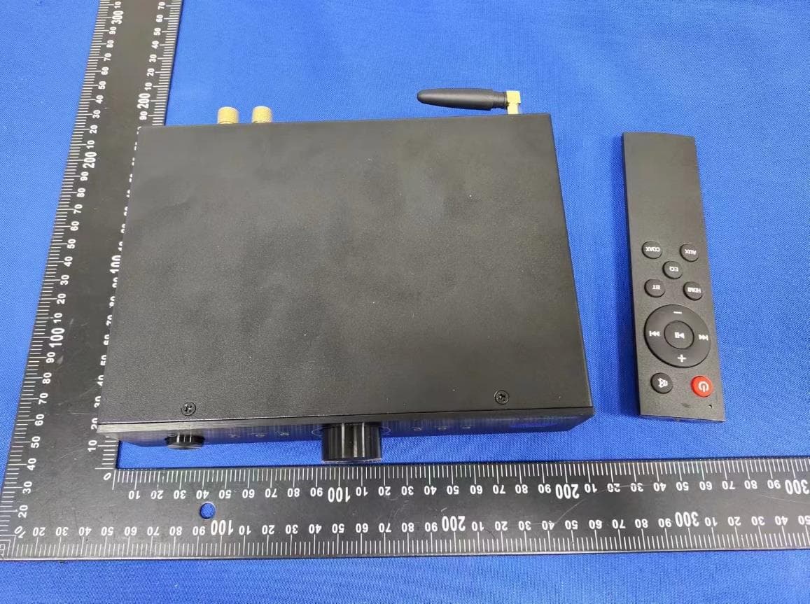
2A4UHNEROSTREAMARC
Sep 01, 2024BT Amplifier
Equipment Class
DSS - Part 15 Spread Spectrum Transmitter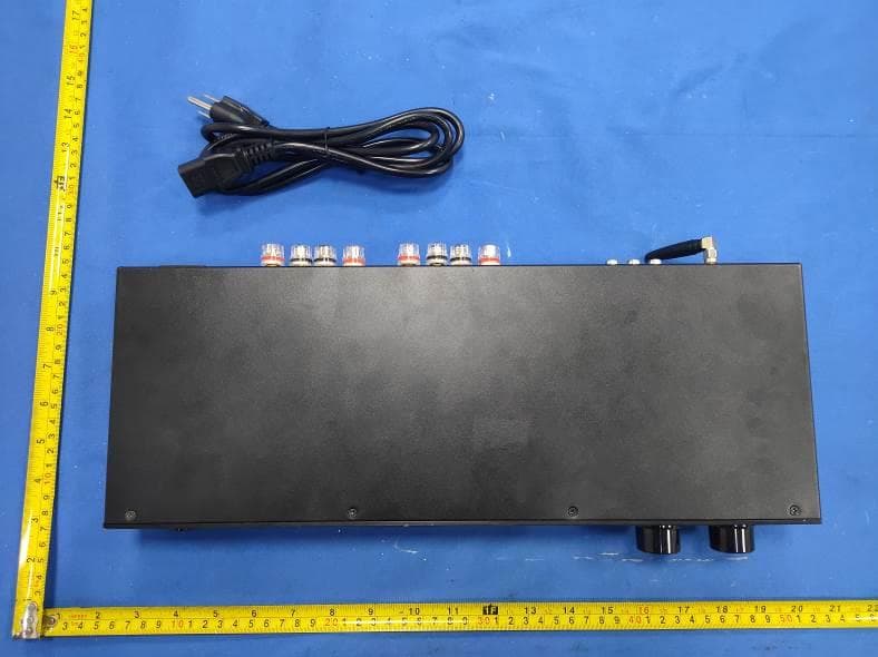
2A4UH-XMP100BT
Jul 22, 2024Bluetooth Amplifier
Equipment Class
DSS - Part 15 Spread Spectrum Transmitter