2A4UHNEROSTREAMARCBT Amplifier
Santos Electronics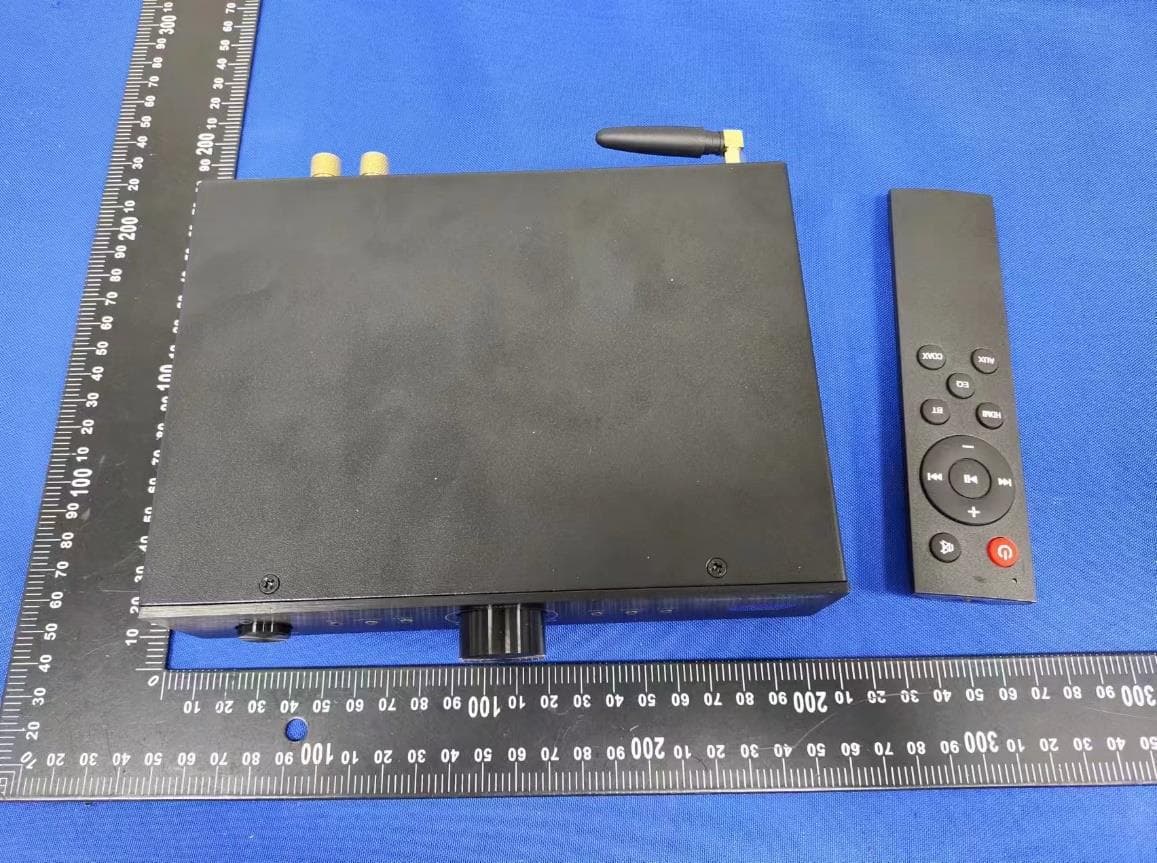
Click to zoom
Application Details
- Equipment Class
- DSS - Part 15 Spread Spectrum Transmitter
- Date of Grant
- Sep 01, 2024
- Application Purpose
- Original Equipment
- Date of Application
- Sep 01, 2024
- Equipment Note
- BT Amplifier
- Frequency Range
- 2402.00000000 - 2480.00000000
- Company
- Santos Electronics
- Country
- United States
Documents & Files
Document Text
Text extracted from the exhibit documents filed with the FCC. Open a document above to read the original.
Users Manual
Stream ARC /BT Ampl ifier Owner’s Manual Important Safety Precautions NERO ARC Introduction ARC Connection Connection Via Wireless BT Receiver Mode Integrated Amp/Preamp, 100-watt per channel RMS Class D Stereo Amplifier with ARC, Wireless, USB plus 3 other inputs, subwoofer output, and remote control. The OSD Nero ARC amplifier makes a great choice for improving the sound from your TV or computer speakers. This versatile amp's ARC, 24/192 USB Audio, BT Wireless, digital, and line- level Inputs ensure connectivity with your existing equipment. With Its range of 6 different inputs, it also makes a great stand-alone Integrated amp. Small enough to be mounted behind your TV. Add A bookshelf, floor-standing speakers, and a subwoofer to get Theater-quality sound. Alternatively, use in-wall speakers for an aesthetically pleasing solution. Improves your laptop or computer sound; connect using ARC, USB, or headphone outputs, add desktop speakers, and transform your home office audio experience. The front-mounted volume control makes it quick and easy to adjust the sound level. Features 2 x 100 Watts RMS 4 Ohms, for high power sound 1 x 200 Watts peak power for maximum dynamics Class D design for maximum efficiency and low-cost running Greater than 95 dB SNR for low noise and clear sound Six separate inputs, including ARC for TV and computer connection Volume, Bass, and Treble controls allow you to ‘dial in’ exactly the sound you want Auto stand-by turns the amp off when not being used. NERO ARC Integrated AMP/PREAMP Owner’s Manual The NERO ARC features Wireless BT Connect as an option. You can access the Wireless BT 5.3 manually using the front panel Volume/Source Select Knob or by using the IR Remote that is included with the NERO ARC. When in receiver mode, the Wireless BT LED will flash, which indicates it is waiting for a connection in your BT Transmitter device (cell phone, pad, TV). You can search for the device name “OSD Player.” Once connected, the BT LED will stay on, which indicates the connection is successful. You can start playing music from the connected device and hear the sound coming out of the connected passive speakers. Connect the ARC-approved HDMI cable to the Input Port labeled ARC or eARC. The other end connects the ARC input on the back panel of the NERO ARC Integrated AMP/PREAMP. This will only work if both connections are ARC-ready. This allows the TV’s audio output through the ARC connection and enables the CEC control between the TV and the NERO ARC device so that the TV remote control can control the NERO ARC without the need for Programming. Note: You will most likely have to change the TV settings, disabling their internal speakers while enabling the audio output through the ARC port of the television. Some TVs may require adjustments for the ARC port to enable the CEC operation. NERO ARC Integrated AMP/PREAMP Connections Analog Line-In/Sub Output Analog Device Audio Out RL Powered Sub Audio Inputs R L LFE Connect any Playback device with Audio out/Line out/Aux out to Line in using an RCA cable. For example, a CD/DVD Player or Headphone connection from your Smartphone. Digital Device Fiber Optic Output Digital Device Laptop Computer USB-A Output Digital Coax Output Digital Optical/Coaxial Inputs Connect any playback device with Digital Fiber output to Optical input using Optical Cable (TV, AVR) Connect the output of the NERO ARC to a Powered Subwoofer Input or Subwoofer Amp input using an RCA Sub Cable, single or single to dual RCA Sub cable DAC USB Type C Input From USB Type A Output Transfer Native Digital signal from your Desktop or Laptop Computer to the DAC Type C Input on the NERO ARC utilizing the Audiophile DAC (Digital to Analog Convertor) featured in the NERO ARC For the other Digital connection, this makes sure you are covered for both Fiber and Coax applications NERO ARC Callouts, Front Panel Front Panel Controls 1.POWER/STATUS INDICATING LIGHT The Green light indicates regular operation, the red light indicates FAULT, and the orange light indicates waveform trim 2. POWER SWITCH Used to turn on or off the power of the internal amplifier 3.VOLUME/SOURCE SELECTION CONTROL KNOB The Volume/Select Knob is rotated to the left (counterclockwise) to turn the volume down and turn to the right (clockwise) to increase the volume. Press the Volume/Select Knob to Cycle through the sources one at a time: Wireless BT, Digital Optical, DAC, ARC, Digital Coax, and Line in. Hold the Volume/Source knob down to restore factory settings. In the standby state, press the Knob to wake up the power amplifier 4.IR WINDOW Used to receive the infrared signal of the remote control The power amplifier has an automatic shutdown function; in the absence of any audio input, it will enter the automatic standby state within 10 minutes; Standby power consumption ≤ 0.5W; you can use the standby button of the remote control or touch the switch through the encoder on the panel to wake up the power amplifier. The power amplifier has a power-off memory function. When powered off and then powered on again, it will return to the parameters before the shutdown, such as EQ, sound source, etc. What’s in the Box IR Remote 2 AAA Batteries Wall Mount Brackets Wireless BT Antenna Power Cord QR Code Warranty Card Amplifier Standby REAR PANEL CONTROLS 5.Wireless BT external antenna To maintain the stability of Wireless BT communication, it is necessary to rely on the assistance of external antennas, which will greatly improve the distance and stability. 6.Digital DAC input Used to play USB C disk music and connect computer playback. 7.Analog AUX input It can play music by connecting to CDs, DVDs, set-top boxes, and other audio sources with analog audio output devices. 8.Speaker output Terminals Five-way Binding posts can connect a pair of 4-ohm, 8-ohm, or two pairs of 8-ohm speakers (with a 4-ohm load). 9.AC outlet It supports AC 100 - 120V/220 - 240V voltage input and can adapt to the power supply volta…
Text truncated - open the document above for the full version.
Attestation Statements
Santos Electronics 2.911 (d)(5)(i) Equipment Type Attestation v1.2 Section 2.911(d)(5)(i) Certification – Equipment Type Company name: Santos Electronics Address: 775 Columbia Street Brea California United States Product Name: BT Amplifier FCC ID: 2A4UHNEROSTREAMARC Model(s): Stream ARC 2.911(d)(5)(i) Equipment Type We, [Santos Electronics] (“the applicant”) certify that the equipment for which authorization is sought through certification is not: Prohibited from receiving an equipment authorization pursuant to § 2.903; of the FCC rules. Identified as an equipment type in the “Covered List” NOTE 1 Yours sincerely, Name: Dave Chai Date: 2024-08-20 Title and Company name: Manager /Santos Electronics NOTE 1 “Covered List”; is the List of Equipment and Services Covered By Section 2 of The Secure Networks Act, available at https://www.fcc.gov/supplychain/coveredlist References; 1) 986446 D01 Covered Equipment v01 https://apps.fcc.gov/oetcf/kdb/forms/FTSSearchResultPage.cfm?switch=P&id=325672 2) Federal Register document 2022-28263 published on 02/06/23 https://www.federalregister.gov/documents/2023/02/06/2022-28263/protecting-against-national-security-threats-to-the-com munications-supply-chain-through-the
Attestation Statements
Santos Electronics 2.911 (d)(5)(ii) Applicant Attestation v1.3 Section 2.911(d)(5)(ii) Certification – Applicant (Covered List ) Company name: Santos Electronics Address: 775 Columbia Street Brea California United States Product Name: BT Amplifier FCC ID: 2A4UHNEROSTREAMARC Model(s): Stream ARC 2.911(d)(5)(ii) Applicant filing We, [Santos Electronics] (“the applicant”) certify that, as of the date of the filing of the application, the applicant is not identified NOTE 1 on the “Covered List” NOTE 2 , established pursuant to § 1.50002 of this chapter, as an entity producing covered communications equipment. Yours sincerely, Name: Dave Chai Date: 2024-08-20 Title and Company name: Manager /Santos Electronics NOTE 1 Delete option not applicable to this application. NOTE 2 “Covered List”; is the List of Equipment and Services Covered By Section 2 of The Secure Networks Act, available at https://www.fcc.gov/supplychain/coveredlist References; 1) 986446 D01 Covered Equipment v01 https://apps.fcc.gov/oetcf/kdb/forms/FTSSearchResultPage.cfm?switch=P&id=325672 2) Federal Register document 2022-28263 published on 02/06/23 https://www.federalregister.gov/documents/2023/02/06/2022-28263/protecting-against-national-security-threats-to-the-com munications-supply-chain-through-the
Attestation Statements
Santos Electronics 775 Columbia Street Brea California United States 2.911 (d)(7)USA Agent v1.3 Federal Communications Commission Authorization and Evaluation Division Equipment Authorization Branch 7435 Oakland Mills Road Columbia, MD 21046 2024-8-20 U.S. Agent Designation Santos Electronics acknowledges their consent for the following contact located in the United States to act as their agent for service of process for the equipment for which authorization is sought (FCC ID: 2A4UHNEROSTREAMARC): Name and company of U.S. agent: Santos Electronics Physical U.S. address of agent: 775 Columbia Street Brea California United States FRN of U.S. agent: 0032004079 Email address of U.S. agent: [email protected] Santos Electronics acknowledges their obligation to accept service of process on behalf of Santos Electronics. Santos Electronics with the FRN [0032004079] accepts its obligation to maintain an agent for service of process in the United States for no less than one year after either the grantee has permanently terminated all marketing and importation of the applicable equipment within the U.S., or the conclusion of any Commission-related administrative or judicial proceeding involving the equipment, whichever is later. By signing this form, we confirm the above and that we are aware of the application requirements listed under §2.911(d)(7). The information provided in this letter is based on the referenced rule parts of Title 47 of the CFR as well as KDB986446 D01. An expiration date for this letter does not exist. In case the U.S. agent changes, the grantee is obligated to notify the FCC within 30 days via the granting TCB. Sincerely, Signature Signature Dave Chai Dave Chai Manager Manager Santos Electronics Santos Electronics Santos Electronics 775 Columbia Street Brea California United States 2.911 (d)(7)USA Agent v1.3
Cover Letter(s)
Santos Electronics Agent Authorization Company: Santos Electronics Address: 775 Columbia Street Brea California United States Product Name: BT Amplifier Model Number(s): Stream ARC Product Description: Frequency in 2402-2480MHz, BT mode operation. We authorize MiCOM Labs Inc., 575 Boulder Court, Pleasanton, California 94566, USA, to act on our behalf on all matters concerning the certification of above named equipment. We declare that MiCOM Labs Inc. is allowed to forward all information related to the approval and certification of equipment to the regulatory agencies as required and to discuss any issues concerning the approval application. Any and all acts carried out by MiCOM Labs on our behalf shall have the same effect as acts of our own. Signature: Date: 2024-08-20 Name: Dave Chai Title: Manager Company: Santos Electronics
Cover Letter(s)
Santos Electronics Office of Engineering Technology Federal Communications Commission 7435 Oakland Mills Road Columbia, MD 21046 USA Date: 2024-08-20 Subject; Request for Confidentiality FCC ID: 2A4UHNEROSTREAMARC To Whom It May Concern, Pursuant to the provisions of the Commission’s rules Title 47 Sections §0.457 and §0.459, we are requesting the Commission to withhold the following attachment(s) as confidential documents from public disclosure indefinitely. These documents contain detailed system and equipment descriptions and are considered as proprietary information in operation of the equipment. The public disclosure of these documents might be harmful to our company and would give competitors an unfair advantage in the market. Schematic Diagram Block Diagram Parts List Operational Description Tune-up Procedure In additional to above mentioned documents, in order to comply with the marketing regulations in Title 47 CFR §2.803 and the importation rules in Title 47 CFR §2.1204, while ensuring that business sensitive information remains confidential until the actual marketing of newly authorized devices, we request Short Term Confidentiality of the following attachment(s); External Photos Test Setup Photos Internal Photos User Manual For 45 days, pursuant to Public Notice DA 04-1705. OR For 180 days pursuant to KDB 726920 D01. It is our understanding that all measurement test reports, FCC ID label format and correspondence during the certification review process cannot be granted as confidential documents and this information will be available for public review once the grant of equipment authorization is issued. Sincerely, Signature: Name: Dave Chai Title: Manager
External Photos
FCC ID: 2A4UHNEROSTREAMARC ANT FCC ID: 2A4UHNEROSTREAMARC FCC ID: 2A4UHNEROSTREAMARC FCC ID: 2A4UHNEROSTREAMARC FCC ID: 2A4UHNEROSTREAMARC
ID Label/Location Info
Label & label location Label size: 18.0cm * 4.5cm label location
Internal Photos
FCC ID: 2A4UHNEROSTREAMARC FCC ID: 2A4UHNEROSTREAMARC ANT FCC ID: 2A4UHNEROSTREAMARC FCC ID: 2A4UHNEROSTREAMARC FCC ID: 2A4UHNEROSTREAMARC FCC ID: 2A4UHNEROSTREAMARC FCC ID: 2A4UHNEROSTREAMARC
RF Exposure Info
RF Exposure evaluation Exposure category: General population/uncontrolled environment EUT Type: Production Unit Device Type: Mobile Device Refer Standard: KDB 447498 D01 General RF Exposure Guidance v06 FCC Part 2 §2.1091 FCC ID: 2A4UHNEROSTREAMARC 1. Reference According to §1.1307(b)(1), systems operating under the provisions of this section shall be operated in a manner that ensures that the public is not exposed to radio frequency energy level in excess of the Commission’s guidelines. According to §1.1310 and §2.1091 RF exposure is calculated. KDB447498 D01: Mobile and Portable Devices RF Exposure Procedures and Equipment Authorization Policies 2. Limit Limits for Maximum Permissible Exposure (MPE)/Controlled Exposure Frequency Range(MHz) Electric Field Strength(V/m) Magnetic Field Strength(A/m) Power Density (mW/cm²) Averaging Time (minute) Limits for Occupational/Controlled Exposure 0.3 – 3.0 614 1.63 (100) * 6 3.0 – 30 1842/f 4.89/f (900/f 2 )* 6 30 – 300 61.4 0.163 1.0 6 300 – 1500 / / f/300 6 1500 – 100,000 / / 5 6 Limits for Maximum Permissible Exposure (MPE)/Uncontrolled Exposure Frequency Range(MHz) Electric Field Strength(V/m) Magnetic Field Strength(A/m) Power Density (mW/cm²) Averaging Time (minute) Limits for Occupational/Controlled Exposure 0.3 – 3.0 614 1.63 (100) * 30 3.0 – 30 824/f 2.19/f (180/f 2 )* 30 30 – 300 27.5 0.073 0.2 30 300 – 1500 / / f/1500 30 1500 – 100,000 / / 1.0 30 F=frequency in MHz *=Plane-wave equivalent power density 3. MPE Calculation Method Predication of MPE limit at a given distance Equation from page 18 of OET Bulletin 65, Edition 97-01 S=PG/4πR² Where: S=power density P=power input to antenna G=power gain of the antenna in the direction of interest relative to an isotropic radiator R=distance to the center of radiation of the antenna 4. Result As declared by the Applicant, the EUT is a wireless device used in a fix application, at least 20 cm from any body part of the user or nearby persons; from the maximum EUT RF output power, the minimum separation distance, r =20cm, as well as the gain of the used BT antenna is 2.36dBi, the RF power density can be obtained. EDR Freq. (MHz) Output Power (dBm) Target power W/ tolerance (dBm) Max tune up power tolerance (dBm) Output power to antenna (mW) Ant Gain (dBi) Power Density at R=20cm (mW/cm2) Limit (mW/c m2) Result GFSK 2402 10.650 11±1.0 12 15.8489 2.5 0.0056 1 Pass 2441 9.696 10±1.0 11 12.5893 2.5 0.0045 1 Pass 2480 9.252 10±1.0 11 12.5893 2.5 0.0045 1 Pass π/4DQPSK 2402 11.445 11±1.0 12 15.8489 2.5 0.0056 1 Pass 2441 10.844 11±1.0 12 15.8489 2.5 0.0056 1 Pass 2480 10.508 10±1.0 11 12.5893 2.5 0.0045 1 Pass 8DPSK 2402 11.498 11±1.0 12 15.8489 2.5 0.0056 1 Pass 2441 11.081 11±1.0 12 15.8489 2.5 0.0056 1 Pass 2480 10.755 11±1.0 12 15.8489 2.5 0.0056 1 Pass Note: The estimation distance is 20cm 5. Conclusion The measurement results comply with the FCC Limit per 47 CFR 2.1091 for the uncontrolled RF Exposure of mobile device.
Test Report
2.4GHzRODANTENNA TECHNICALDATASHEET DZP(TX2400-JW-5RP) VERSION:3.3DATE:2023-08-01 TEL:028-61542639WEBSITE:WWW.ZIISOR.COM CHENGDUZIISORTECHNOLOGYCO.,LTD.EXPERTOFIOTANTENNA DZP(TX2400-JW-5RP) 1 / 5 Copyright@ChengduZiisorTechnologyCo.,Ltd2020Expert of IoT Antenna DZP(TX2400-JW-5RP) NO.MECHANICAL SPECIFICATIONSVALUECOMMENT 01Part NumberDZP(TX2400-JW-5PR)2.4GHz Rod Antenna 02MaterialTPEE 03Material of RadiatorCopper 04Connector TypeSMA-K 05Antenna ColourBlack 06Overall Length50mmOD10mm 07Cable TypeN/A 08Cable LengthN/A 09Weight6g±1g NO.ELECTRICAL SPECIFICATIONSVALUECOMMENT 01Frequency2.4GHz2.4-2.5GHz 02Antenna Gain2.5dBi 03Radiation typeOmnidirectional 04PolarizationLinearVertical 05Nominal Impedance50Ω 06Power Capacity10W 07S.W.R.≤1.5 NO.ENVIRONMENTAL SPECIFICATIONSVALUECOMMENT 01Operation Temperature-30°C~+75°C 02Storage Temperature-30°C~+75°C 03RoHS CompliantYES DZP(TX2400-JW-5RP) 2/5 Copyright@ChengduZiisorTechnologyCo.,Ltd2020ExpertofIoTAntenna S.W.R. SMITH DZP(TX2400-JW-5RP) 3/5 Copyright@ChengduZiisorTechnologyCo.,Ltd2020ExpertofIoTAntenna RADIATIONPATTERN 2.4GHz 2.45GHz 2.5GHz DISCLAIMER Inordertoprovideouruserswithbetterservice,ChengduZiisorTechnologyCo.,Ltd(hereinafter referredtoasziisor)willtrytopresentasdetailedandaccurateproductinformationaspossiblein thismanual.However,duetothetimelinessofthemanualcontent,ziisorshallnotabsolutelyguarantee theunlimitedtimelinessandapplicabilityofthefile.Ziisorhastherighttoupdatethemanualcontent withoutfurthernotice.Togetthelatesteditioninformation,plsvisittheofficialwebsiteofziisor orcontactourcustomerservicestaff.Thanksforyourtrustandsupport! DZP(TX2400-JW-5RP) 4/5 Copyright@ChengduZiisorTechnologyCo.,Ltd2020ExpertofIoTAntenna CONTACTUS CompanyNameChengduZiisorTechnologyCo.,Ltd Telephone+86-028-61542639 Websitewww.ziisor.com [email protected] [email protected] CompanyAddress B5MoldingToolIndustryPark,No.199XiQuAvenue, Chengdu,China
Test Report
Page 1 of 57 Hotline:400-8868-419Fax:86-755-27790922http://www.ncttesting.cn FCCPart15CTESTREPORT FCCID:2A4UHNEROSTREAMARC Product:BTAmplifier ModelName:StreamARC Brand:OSDNERO ReportNo.:NCT24029553 Preparedfor SantosElectronics 775ColumbiaStreetBreaCaliforniaUnitedStates Preparedby ShenzhenNCTTestingTechnologyCo.,Ltd. A101&2FB2,Fuqiao6thArea,XintianCommunity,FuhaiStreet,BaoanDistrict, Shenzhen,People’sRepublicofChina TEL:400-8868-419 FAX:86-755-27790922 ReportNo:NCT24029553 Page 2 of 57 Hotline:400-8868-419Fax:86-755-27790922http://www.ncttesting.cn 1TESTRESULTCERTIFICATION Applicant’sname:SantosElectronics Address:775ColumbiaStreetBreaCaliforniaUnitedStates Manufacture'sname:SantosElectronics Address:775ColumbiaStreetBreaCaliforniaUnitedStates Productname:BTAmplifier Modelname:StreamARC Standards:FCCCFR47Part15Section15.247 Testprocedure:ANSIC63.10:2013 TestDate:Jun.30~Jul.24,2024 DateofIssue:Jul.29,2024 TestResult:Pass ThisdevicedescribedabovehasbeentestedbyNCT,andthetestresultsshowthatthe equipmentundertest(EUT)isincompliancewiththeFCCrequirements.Anditisapplicable onlytothetestedsampleidentifiedinthereport. Thisreportshallnotbereproducedexceptinfull,withoutthewrittenapprovalofNCT,this documentmaybealteredorrevisedbyNCT,personalonly,andshallbenotedintherevision ofthedocument. TestEngineer: HughZhang/Engineer TechnicalManager: HenryWang/Manager ReportNo:NCT24029553 Page 3 of 57 Hotline:400-8868-419Fax:86-755-27790922http://www.ncttesting.cn Contents Page 1TESTRESULTCERTIFICATION...............................................................................................................................2 2TESTSUMMARY..........................................................................................................................................................5 3TESTFACILITY.............................................................................................................................................................6 4GENERALINFORMATION..........................................................................................................................................7 4.1GENERALDESCRIPTIONOFE.U.T.....................................................................................................................7 4.2CHANNELLIST.....................................................................................................................................................8 4.3TESTSETUPCONFIGURATION............................................................................................................................9 4.4TESTMODE.........................................................................................................................................................9 5EQUIPMENTDURINGTEST....................................................................................................................................10 5.1EQUIPMENTSLIST.............................................................................................................................................10 5.2MEASUREMENTUNCERTAINTY.........................................................................................................................12 5.3DESCRIPTIONOFSUPPORTUNITS...................................................................................................................12 6CONDUCTEDEMISSION..........................................................................................................................................13 6.1E.U.T.OPERATION............................................................................................................................................13 6.2EUTSETUP.......................................................................................................................................................13 6.3TESTSET-UP(BLOCKDIAGRAMOFCONFIGURATION).................................................................................14 6.4MEASUREMENTPROCEDURE:...........................................................................................................................14 6.5CONDUCTEDEMISSIONLIMIT...........................................................................................................................14 6.6MEASUREMENTDESCRIPTION..........................................................................................................................14 6.7CONDUCTEDEMISSIONTESTRESULT.............................................................................................................14 7RADIATEDSPURIOUSEMISSIONS......................................................................................................................17 7.1EUTOPERATION...............................................................................................................................................17 7.2TESTSETUP......................................................................................................................................................18 7.3SPECTRUMANALYZERSETUP..........................................................................................................................19 7.4TESTPROCEDURE.............................................................................................................................................20 7.5SUMMARYOFTESTRESULTS...........................................................................................................................21 8MAXIMUMPEAKOUTPUTPOWERTEST............................................................................................................28 8.1TESTSTANDARDANDLIMIT..............................................................................................................................28 8.2TESTSETUP......................................................................................................................................................28 ReportNo:NCT24029553 Page 4 of 57 Ho…
Text truncated - open the document above for the full version.
Test Report
ReportNo:NCT24029553 Page45of57 Hotline:400-8868-419Fax:86-755-27790922http://www.ncttesting.cn NumberofPulsesin31.6seconds GFSK_DH5 PulseWidth GFSK_DH5 NumberofPulsesin31.6seconds GFSK_DH5 PulseWidth GFSK_DH5 NumberofPulsesin31.6seconds π/4DQPSK_2-DH5 PulseWidth π/4DQPSK_2-DH5 ReportNo:NCT24029553 Page46of57 Hotline:400-8868-419Fax:86-755-27790922http://www.ncttesting.cn NumberofPulsesin31.6seconds π/4DQPSK_2-DH5 PulseWidth π/4DQPSK_2-DH5 NumberofPulsesin31.6seconds π/4DQPSK_2-DH5 PulseWidth π/4DQPSK_2-DH5 NumberofPulsesin31.6seconds 8DPSK_3-DH5 PulseWidth 8DPSK_3-DH5 ReportNo:NCT24029553 Page47of57 Hotline:400-8868-419Fax:86-755-27790922http://www.ncttesting.cn NumberofPulsesin31.6seconds 8DPSK_3-DH5 PulseWidth 8DPSK_3-DH5 NumberofPulsesin31.6seconds 8DPSK_3-DH5 PulseWidth 8DPSK_3-DH5 ReportNo:NCT24029553 Page48of57 Hotline:400-8868-419Fax:86-755-27790922http://www.ncttesting.cn 13100kHzBandwidthofFrequencyBandEdgeRequirement 13.1TestStandardandLimit TestStandard FCCPart15CSection15.247(d) TestLimit inany100kHzbandwidthoutsidethefrequencybandsinwhichthe spreadspectrumintentionalradiatorinoperating,theradiofrequency powerthatisproducedbytheintentionalradiatorshallbeatleast20dB belowthatinthe100kHzbandwidthwithinthebandthatcontainsthe highestlevelofthedesiredpower,Inaddition,radiatedemissionswhich fallintherestrictedbands,asdefinedin§15.205(a),mustalsocomply withtheradiatedemissionlimitsspecifiedin15.209(a). 13.2TestSetup 13.3TestProcedure TheEUTmusthaveitshopping/Non-hoppingfunctionenabled.Usingthefollowingspectrum analyzersetting: 1.SettheRBW=100kHz. 2.SettheVBW=300kHz. 3.Sweeptime=autocouple. 4.Detectorfunction=peak. 5.Tracemode=maxhold. 6.Allowtracetofullystabilize. ReportNo:NCT24029553 Page49of57 Hotline:400-8868-419Fax:86-755-27790922http://www.ncttesting.cn 13.4TestData Non-Hopping ModulationPacketChannel OOBEmission Frequency (MHz) OOB Emission Level (dBm) Limit (dBm) OverLimit (dB) Result GFSKDH1 0 2397.46-40.541-9.3-31.241PASS 2400.00-47.225-9.3-37.925PASS 397205.90-32.154-9.3-22.854PASS 78 4881.79-34.962-10.26-24.702PASS 2483.50-53.816-10.63-43.186PASS π/4DQPSK2-DH1 0 4959.83-39.614-10.63-28.984PASS 2400.00-33.608-9.35-24.258PASS 397205.93-31.143-9.35-21.793PASS 78 4882.42-33.596-10.34-23.256PASS 2483.50-46.445-10.76-35.685PASS 8DPSK3-DH1 0 4960.45-35.620-10.76-24.860PASS 2400.00-35.267-9.38-25.887PASS 394803.76-30.098-9.38-20.718PASS 78 4881.79-31.475-10.28-21.195PASS 2483.50-48.039-10.75-37.289PASS Hopping ModulationPacketChannel OOBEmission Frequency (MHz) OOB Emission Level (dBm) Limit (dBm) OverLimit (dB) Result GFSKDH1 Hopping 2391.80-39.934-9.4-30.534PASS 2400.00-43.044-9.4-33.644PASS π/4DQPSK2-DH1 2483.50-43.071-10.59-32.481PASS 2400.00-33.998-9.39-24.608PASS 8DPSK3-DH1 2483.50-42.908-10.54-32.368PASS 2400.00-35.386-9.42-25.966PASS ReportNo:NCT24029553 Page50of57 Hotline:400-8868-419Fax:86-755-27790922http://www.ncttesting.cn 30.0MHz-25000.0MHz GFSK_DH1_Channel0 30.0MHz-25000.0MHz π/4DQPSK_2-DH1_Channel0 OutOfBandEmission GFSK_DH1_Channel0 OutOfBandEmission π/4DQPSK_2-DH1_Channel0 30.0MHz-25000.0MHz30.0MHz-25000.0MHz ReportNo:NCT24029553 Page51of57 Hotline:400-8868-419Fax:86-755-27790922http://www.ncttesting.cn GFSK_DH1_Channel39π/4DQPSK_2-DH1_Channel39 OutOfBandEmission GFSK_DH1_Channel39 OutOfBandEmission π/4DQPSK_2-DH1_Channel39 30.0MHz-25000.0MHz GFSK_DH1_Channel78 30.0MHz-25000.0MHz π/4DQPSK_2-DH1_Channel78 OutOfBandEmissionOutOfBandEmission ReportNo:NCT24029553 Page52of57 Hotline:400-8868-419Fax:86-755-27790922http://www.ncttesting.cn GFSK_DH1_Channel78π/4DQPSK_2-DH1_Channel78 30.0MHz-25000.0MHz 8DPSK_3-DH1_Channel0 OutOfBandEmission 8DPSK_3-DH1_Channel0 30.0MHz-25000.0MHz 8DPSK_3-DH1_Channel39 OutOfBandEmission 8DPSK_3-DH1_Channel39 30.0MHz-25000.0MHzOutOfBandEmission ReportNo:NCT24029553 Page53of57 Hotline:400-8868-419Fax:86-755-27790922http://www.ncttesting.cn 8DPSK_3-DH1_Channel788DPSK_3-DH1_Channel78 OutOfBandEmission(Left) GFSK_DH1_ChannelHopping OutOfBandEmission(Left) π/4DQPSK_2-DH1_ChannelHopping OutOfBandEmission(Right) GFSK_DH1_ChannelHopping OutOfBandEmission(Right) π/4DQPSK_2-DH1_ChannelHopping OutOfBandEmission(Left)OutOfBandEmission(Right) ReportNo:NCT24029553 Page54of57 Hotline:400-8868-419Fax:86-755-27790922http://www.ncttesting.cn 8DPSK_3-DH1_ChannelHopping8DPSK_3-DH1_ChannelHopping ReportNo:NCT24029553 Page55of57 Hotline:400-8868-419Fax:86-755-27790922http://www.ncttesting.cn 14AntennaRequirement 14.1TestStandardandRequirement TestStandard FCCPart15Section15.203/247(c) Requirement 1)15.203requirement: Anintentionalradiatorshallbedesignedtoensurethatnoantennaotherthan thatfurnishedbytheresponsiblepartyshallbeusedwiththedevice.The useofapermanentlyattachedantennaorofanantennathatusesaunique couplingtotheintentionalradiator,themanufacturermaydesigntheunitso thatabrokenantennacanbereplacedbytheuser,buttheuseofastandard antennajackorelectricalconnectorisprohibited. 2)15.247(c)(1)(i)requirement: Systemsoperatinginthe2400-2483.5MHzbandthatisusedexclusivelyfor fixed.Point-to-pointoperationsmayemploytransmittingantennaswith directionalgaingreaterthan6dBiprovidedthemaximumconductedoutput poweroftheintentionalradiatorisreducedby1dBforevery3dBthatthe directionalgainoftheantennaexceeds6dBi. 14.2AntennaConnectedConstruction TheEUTantennaisanExternalantenna,anditsantennagainis2.5dBi,whichmeetsthe standardrequirements. ReportNo:NCT24029553 Page56of57 Hotline:400-8868-419Fax:86-755-27790922http://www.ncttesting.cn 15APPENDIXI--TESTSETUPPHOTOGRAPH Pleaseseetheattachmentfordetails. ReportNo:NCT24029553 Page57of57 Hotline:400-8868-419Fax:86-755-27790922http://www.ncttesting.cn 16APPENDIXII--EUTPHOTOGRAPH Pleaseseetheattachmentfordetails. ----------------EndofReport---------------
Test Setup Photos
FCC ID: 2A4UHNEROSTREAMARC Radiated Emission (Below 1G) Radiated Emission (Above 1G) Conducted Em…
Text truncated - open the document above for the full version.
Contact Information
Applicant
Dave Chai
Technical Contact
Test Firm
SHENZHEN NCT TESTING TECHNOLOGY CO., LTD.Henry Wang
[email protected]0755-27790922
Technical Specifications
| # | Rule Parts | Frequency Range | Power Output |
|---|---|---|---|
| 1 | 15C | 2.40 GHz - 2.48 GHz | 14.10 mW |
Other Applications from Santos Electronics
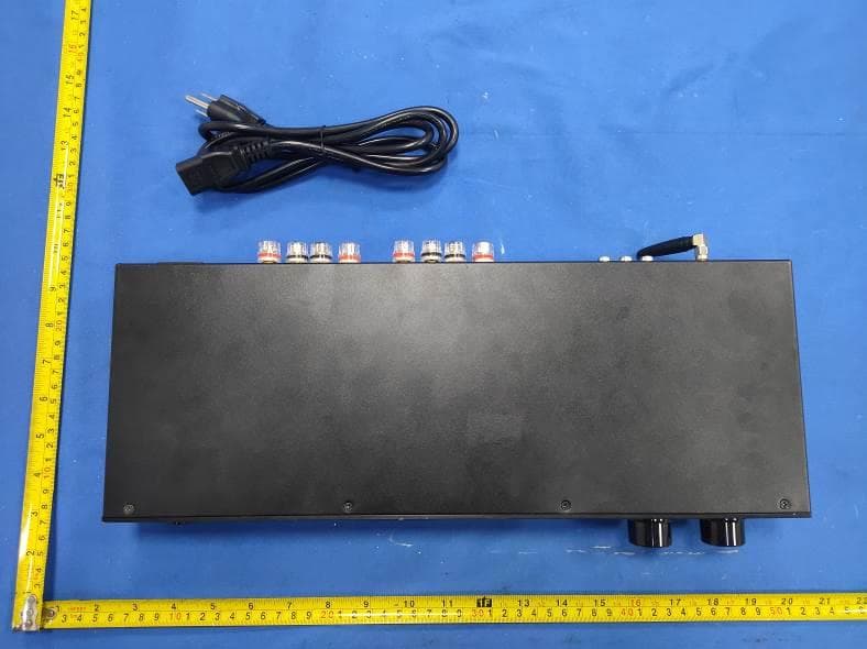
2A4UH-XMP100BT
Jul 22, 2024Bluetooth Amplifier
Equipment Class
DSS - Part 15 Spread Spectrum Transmitter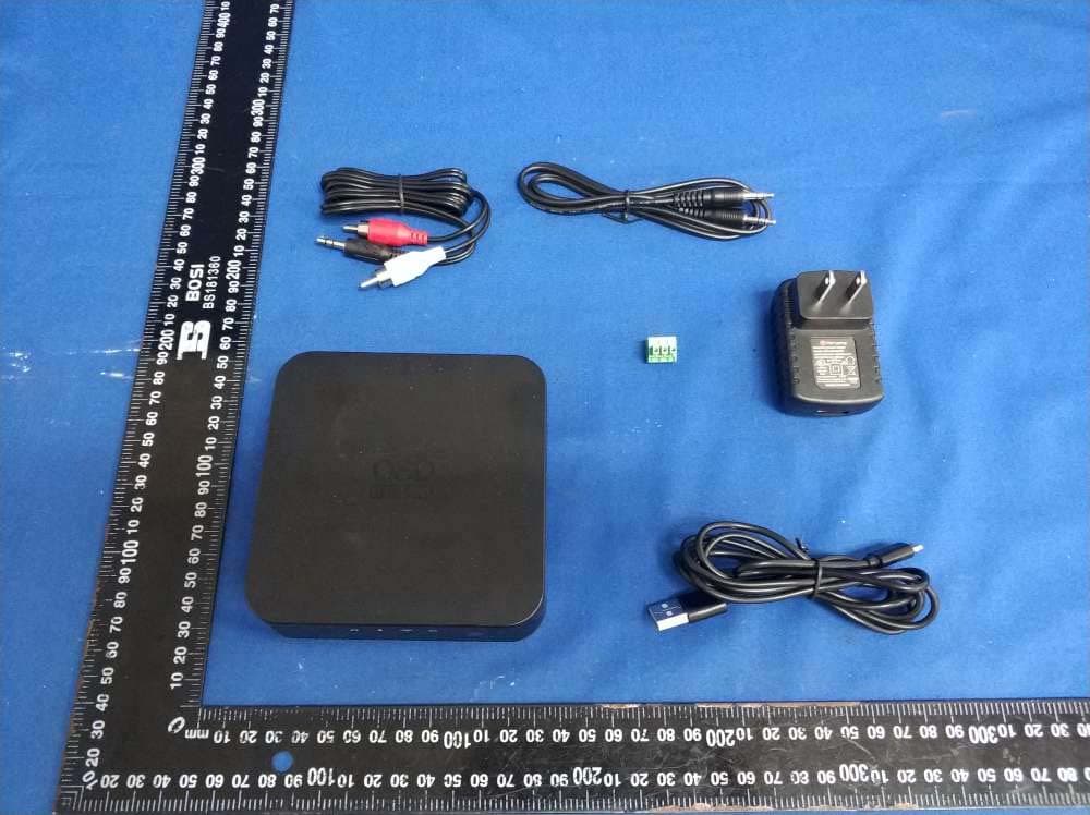
2A4UH-SRT1
Apr 24, 2022HI-FI DAC MUSIC STREAM MODULE
Equipment Class
DTS - Digital Transmission System