2A4UH-XMP100BTBluetooth Amplifier
Santos Electronics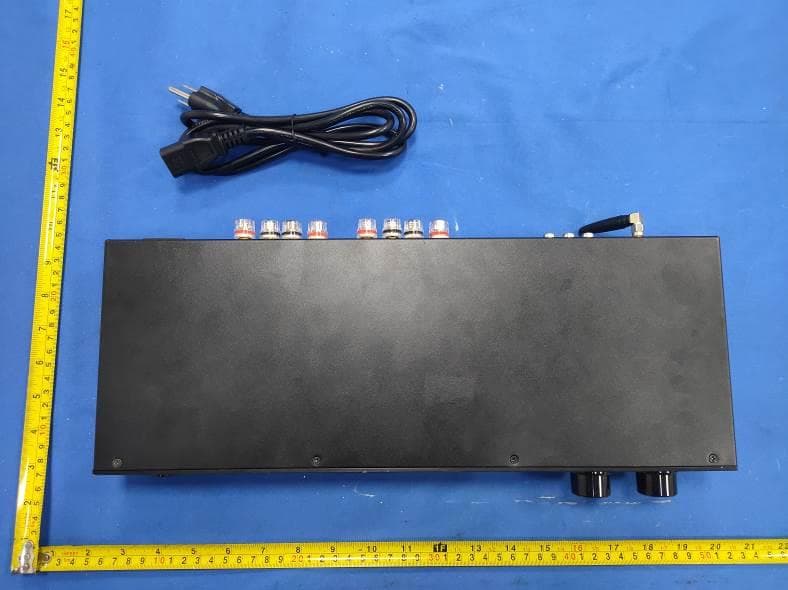
Click to zoom
Application Details
- Equipment Class
- DSS - Part 15 Spread Spectrum Transmitter
- Date of Grant
- Jul 22, 2024
- Application Purpose
- Original Equipment
- Date of Application
- Jul 22, 2024
- Equipment Note
- Bluetooth Amplifier
- Frequency Range
- 2402.00000000 - 2480.00000000
- Company
- Santos Electronics
- Country
- United States
Documents & Files
Document Text
Text extracted from the exhibit documents filed with the FCC. Open a document above to read the original.
Users Manual
XMP300BT Gen2 / XMP100BT Gen2 Stereo Power Amplifiers OWNERS’S MANUAL 775 Columbia St, Brea, CA 92821 www.osdaudio.com Cover Sheet XMP100BT Gen2 / XMP300BT Gen2 Congratulations on your purchase of this product. Please take a few moments to read this entire manual, And be sure to retain this document for future reference. Please read and observe all safety instructions detailed. NOTE: If any part of this product is damaged or missing, please call your dealer. Please read your warranty and retain your receipt and original carton for possible future use. FEATURES: XMP100BT Gen2 / XMP300BT Gen2 •Automatic Source Switching Interrupt-Priority/Main •Main Input with Main Output Pass thru •Speaker A or B, A and B w/Front panel Switches’ •Front Panel Balance and Volume Controls •Signal Sensing “Power On” and Trigger In/Out •Rear Mounted Bass and Treble Controls •Internal Bluetooth Source/ USB Music Playback 1.Power Switch Power On (Green LED) or OFF LED changes to Red when in Standby 2.Speaker Selector Select Speaker A or Speaker B or Both at once 1 2 34 FRONT PANEL CONTROLS 3.Balance Knob Fades Speaker output between the R & L Channels 4. Volume Control Knob Adjusts Volume Level XMP100BT Gen2 775 Columbia St, Brea, CA 92821 www.osdaudio.com 1 XMP100BT Gen2 / XMP300BT Gen2 REAR PANEL XMP300BT Gen2 XMP100BT Gen2 775 Columbia St, Brea, CA 92821 www.osdaudio.com 2 XMP100BT Gen2 / XMP300BT Gen2 XMP300BT Gen2 Specifications: ModelXMP100BT Gen2XMP300BT Gen2 Amplifier TypeStereo Four Channel (2A, 2B)Stereo Four Channel (2A, 2B) Design TypeDigital Class DDigital Class D Bluetooth (version)Bluetooth V5.3Bluetooth V5.3 Rated Output Power200 Watts Max600 Watt Max 8-Ohm Load50W x 2 Channel RMS/Output 8-ohm 150W x 2Chanel RMS/Output 8-ohm 4-Ohm Load100W x 2 Channel RMS/Outout 4-ohm300W x 2 Channel RMS/Output 4-ohm Bridged Mono200W X 1 Channel RMS (A or B)/Output 8Ω600W X 1 Channel (A or B)/Output 8Ω Frequency Response20Hz -20kHz20Hz -20kHz Impedance8-Ohm to 4-Ohm Stable8-Ohm to 4-Ohm Stable Signal to Noise Ratio 90 ≥ dB 100W output into 4-ohms 20kHz90 ≥ dB 300W output into 4-ohms 20kHz 20kHz Lowpass Filter20kHz Lowpass Filter Channel Seperation50dB @1kHz referred to 50W Output into 8Ω50dB @1kHz referred to 150W Output into 8Ω Input Sensitivity700mV Input rated 50W Ouptu into 8Ω700mV Input rated 150W Output into 8Ω Sources/InputsBluetooth/USB/Line-In (Interupt/Main)Bluetooth/USB/Line-In (Interupt/Main) OutputSignal (low) level/Speaker (High) Level OutputsSignal (low) level/Speaker (High) Level Outputs THD «1% @ ouput Rated power /«1% @ ouput Rated power / « 0.07%@ output 1~80W« 0.07%@ output 1~240W Bass and Treble Controls (+/-) 12dB @ 100Hz and 10kHz(+/-) 12dB @ 100Hz and 10kHz Other Back PanelControlsTrigger Functions/Bridged Mono-StereoTrigger Functions/Bridged Mono-Stereo Front Panel Controls Power/Speaker (A/B)/Balance/VolumePower/Speaker (A/B)/Balance/Volume AC Power Multi-Voltage 100V-240V 50-60Hz/250VMulti-Voltage 100V-240V 50-60Hz/250V Dimensions 430mm W x 44.0mm H x 159.4mm D430mm W x 44.0mm H x 201.20mm D 16.92" W x 1.73" H x 6.27" D16.92" W x 1.73" H x 7.92" D Net Weight 2.4 KG/5.29 Pounds3.2 KG/7.05 Pounds 775 Columbia St, Brea, CA 92821 www.osdaudio.com 3 XMP100BT Gen2 / XMP300BT Gen2 In this configuration, the mode switch is set to “Stereo”. Connect the line out jacks from a stereo pre-amplifier or source to the MAIN input jacks of your XMP300BT Gen2. Next connect your speakers to the terminals marked “Speaker A” observing proper polarity. Select the “A” speakers using the front panel zone selection buttons. Connect a second (optional) pair of speakers to the terminals marked “Speaker B”. If you are connecting 4 speakers to the XMP300BT Gen2 they must be 8-ohm speakers only. Press A and B together to use both zones In the multiple source set up, a distributed audio system is connected to the XMP300BT Gen2 as a local zone amplifier via the MAIN inputs. Normally the distributed audio system will be the audio source for the XMP300BT Gen2 The distributed audio is then passed on to be used by additional zones or sub zones in the distributed system via the MAIN outputs. SETUP FOR MULTIPLE SOURCE APPLICATIONS STEREO SETUP (From Local Source Line Out) (From Pre-amp Line Out) (Out to Additional Zones) The audio output of a local source, such as an MP3 Player, CD, television, computer, etc., is connected to the XMP300BT Gen2 via the INTERRUPTING inputs, and whenever the local source is active its signal will take priority over the distributed audio signal present at MAIN input . However, the distributed audio signal will still be present at the MAIN input. In this circumstance the audio output of the local source will be heard via the XMP300BT Gen2. Once the local source is turned off or muted, the XMP300BT Gen2 will automatically switch back to the distributed audio system as an audio source, assuming the local source remains inactive. There is a delay of up to 6 seconds when switching from INTERRUPTING input back to MAIN inputs. Pair Button located on the Back Panels of the XMP100/300 BT Gen2. Press the White Button, see the Front Panel Blue Power Button LED indicator starts to Flash in Setup m ode. Select OSD BT SPKR on the Bluetooth Enabled Device. If the connection is successful, The Power LED will change from Flashing to a steady Blue. PAIRING BLUETOOTH Front Panel Power Button w/Status LED Back Panel RCA Inputs/outputs Back Panel RCA Inputs/outputs Back Panel Bluetooth Pairing Button 775 Columbia St, Brea, CA 92821 www.osdaudio.com 4 XMP100BT Gen2 / XMP300BT Gen2 775 Columbia St, Brea, CA 92821 www.osdaudio.com 5 XMP100BT Gen2 / XMP300BT Gen2 775 Columbia St, Brea, CA 92821 www.osdaudio.com 6 LimitedWarranty OSDAudio warrantsitsamplifierproductsagainstdefectsinmaterialsandworkmanshipforalimitedperiodof time.Foraperiodoftwoyearsfromdateoforiginalpurchase,wewillrepairorreplacetheproduct,atouroption, withoutchargeforpartsandlabor.Customermustpayallpartsandlaborchargesafterthelimitedwarranty periodexpir…
Text truncated - open the document above for the full version.
Attestation Statements
Santos Electronics 775 Columbia Street Brea California United States Federal Communications Commission Authorization and Evaluation Division Equipment Authorization Branch 7435 Oakland Mills Road Columbia, MD 21046 2024-7-23 To whom it may concern: We, Santos Electronics, hereby certify that the equipment for which authorization is sought (FCC ID: 2A4UH-XMP100BT) is not “covered” equipment prohibited from receiving an equipment authorization pursuant to § 2.903 of the FCC rules. We also certify that, as of the date of the filing of the application, we are not identified on the Covered List (https://www.fcc.gov/supplychain/coveredlist) as an entity producing “covered” equipment. By signing this form, we confirm the above and that we are aware of the application requirements listed under § 2.911(b) and (d)(5) and (6). The information provided in this letter is based on the referenced rule parts of Title 47 of the CFR as well as KDB 986446 D01. Sincerely, Signature Dave Chai Manager Santos Electronics 62_[model] CoveredEqu_2.911(d)(5 )(i) and (ii) - U, V03
Attestation Statements
Santos Electronics 775 Columbia Street Brea California United States Federal Communications Commission Authorization and Evaluation Division Equipment Authorization Branch 7435 Oakland Mills Road Columbia, MD 21046 2024-7-23 U.S. Agent Designation Santos Electronics acknowledges their consent for the following contact located in the United States to act as their agent for service of process for the equipment for which authorization is sought (FCC ID: 2A4UH-XMP100BT): Name and company of U.S. agent: Santos Electronics Physical U.S. address of agent: 775 Columbia Street Brea California United States FRN of U.S. agent: 0032004079 Email address of U.S. agent: [email protected] Santos Electronics acknowledges their obligation to accept service of process on behalf of Santos Electronics. Santos Electronics with the FRN [0032004079] accepts its obligation to maintain an agent for service of process in the United States for no less than one year after either the grantee has permanently terminated all marketing and importation of the applicable equipment within the U.S., or the conclusion of any Commission-related administrative or judicial proceeding involving the equipment, whichever is later. By signing this form, we confirm the above and that we are aware of the application requirements listed under § 2.911(d)(7). The information provided in this letter is based on the referenced rule parts of Title 47 of the CFR as well as KDB 986446 D01. An expiration date for this letter does not exist. In case the U.S. agent changes, the grantee is obligated to notify the FCC within 30 days via the granting TCB. Sincerely, Signature Dave Chai Manager Santos Electronics Signature Dave Chai Manager Santos Electronics 48_[mo del] US_Agent_2.911(d)(7) - U, V0 5
Cover Letter(s)
CONFIDENTIALITY REQUEST for Certification Service in USA Federal Communication Commission Equipment Authorization Division, Application Processing Branch 7435 Oakland Mills Road Columbia, MD 21046 Date:<2024-7-23> Pursuant to Paragraphs §0.457 and 0.459 of the Commission’s Rules (47 C.F.R.) and Section §552(b)(4) of the Freedom of Information Act, we requests confidentiality for the following products: FCC ID Model name 2A4UH-XMP100BT XMP 100BT For the product stated above, we request that the following information be held confidential; Exhibits Long-Term Confidentiality Short-Term Confidentiality Short-Term Confidentiality Days External Photos Internal Photos Block Diagram Schematics Test Setup Photos User’s Manual Parts List Tune Up Operational Descriptions The long-term confidentiality exhibits contain our trade secrets and proprietary information that could be of benefit to our competitors. The short-term confidentiality on the basis of ensuring that business sensitive information remains confidential until the actual marketing of our new device. If you have any questions, please feel free to contact me at the address shown below. Sincerely, Name/Title: Dave Chai/Manager Company: Santos Electronics Address: 775 Columbia Street Brea California United States Phone: 5626972600 Fax: 5626972600 E-Mail: [email protected]
Cover Letter(s)
Santos Electronics 775 Columbia Street Brea California United States Federal Communications Commission Authorization and Evaluation Division Equipment Authorization Branch 7435 Oakland Mills Road Columbia, MD 21046 2024-7-23 To whom it may concern: We, the undersigned, hereby authorize Eurofins Product Service GmbH to act on our behalf in all matters relating to applications for equipment authorization FCC ID: 2A4UH-XMP100BT including the signing of all documents related to these matters. Any and all acts carried out by Eurofins Product Service GmbH on our behalf shall have the same effect as acts of our own. By signing this application form, we agree to Eurofins’ current valid General Terms and Conditions (AGB),Testing and Certification Regulations (PZO) which can be viewed on following website www.eurofins.de/ee or retrieved on request. We also hereby certify that no party to this application is subject to a denial of benefits, including FCC benefits, pursuant to Section 5301 of the Anti-Drug Abuse Act of 1988, 21 U.S.C. 862. Sincerely, Name/Title: Dave Chai/Manager Company: Santos Electronics Address: 775 Columbia Street Brea California United States Phone: 5626972600 Fax: 5626972600 E-Mail: [email protected]
External Photos
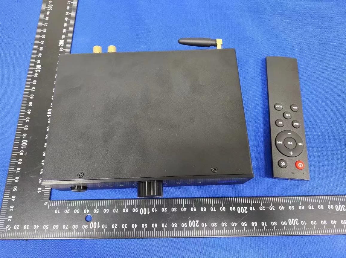
FCC ID: 2A4UH-XMP100BT External Photos of the EUT ANT FCC ID: 2A4UH-XMP100BT FCC ID: 2A4UH-XMP100BT
RF Exposure Info
RF Exposure evaluation FCC ID: 2A4UH-XMP100BT Exposure category: General population/uncontrolled environment EUT Type: Production Unit Device Type: Mobile Device 1. Reference According to §1.1307(b)(1), systems operating under the provisions of this section shall be operated in a manner that ensures that the public is not exposed to radio frequency energy level in excess of the Commission’s guidelines. According to §1.1310 and §2.1091 RF exposure is calculated. KDB447498 D01: Mobile and Portable Devices RF Exposure Procedures and Equipment Authorization Policies 2. Limit Limits for Maximum Permissible Exposure (MPE)/Controlled Exposure Frequency Range(MHz) Electric Field Strength(V/m) Magnetic Field Strength(A/m) Power Density (mW/cm²) Averaging Time (minute) Limits for Occupational/Controlled Exposure 0.3 – 3.0 3.0 – 30 30 – 300 300 – 1500 1500 – 100,000 614 1842/f 61.4 / / 1.63 4.89/f 0.163 / / (100) * (900/f 2 )* 1.0 f/300 5 6 6 6 6 6 Limits for Maximum Permissible Exposure (MPE)/Uncontrolled Exposure Frequency Range(MHz) Electric Field Strength(V/m) Magnetic Field Strength(A/m) Power Density (mW/cm²) Averaging Time (minute) Limits for Occupational/Controlled Exposure 0.3 – 3.0 3.0 – 30 30 – 300 300 – 1500 1500 – 100,000 614 824/f 27.5 / / 1.63 2.19/f 0.073 / / (100) * (180/f 2 )* 0.2 f/1500 1.0 30 30 30 30 30 F=frequency in MHz *=Plane-wave equivalent power density 3. MPE Calculation Method Predication of MPE limit at a given distance Equation from page 18 of OET Bulletin 65, Edition 97-01 S=PG/4πR² Where: S=power density P=power input to antenna G=power gain of the antenna in the direction of interest relative to an isotropic radiator R=distance to the center of radiation of the antenna 4. Antenna Information XMP 100BT can only use antennas certificated as follows provided by manufacturer; Antenna No. Model No. of antenna: Type of antenna: Gain of the antenna (Max.) Frequency range: BT / External antenna 2.00dBi for 2400-2500MHz; 5. Manufacturing Tolerance GFSK(Peak) Channel Channel 00 Channel 39 Channel 78 Target (dBm) -2.0 -2.0 -3.0 Tolerance ±(dB) 1.0 1.0 1.0 π/4DQPSK (Peak) Channel Channel 00 Channel 39 Channel 78 Target (dBm) 0.0 -2.0 -2.0 Tolerance ±(dB) 1.0 1.0 1.0 8DPSK (Peak) Channel Channel 00 Channel 39 Channel 78 Target (dBm) 0.0 -2.0 -2.0 Tolerance ±(dB) 1.0 1.0 1.0 6. Standalone MPE Result As declared by the Applicant, the EUT is a wireless device used in a fix application, at least 20 cm from any body part of the user or nearby persons; from the maximum EUT RF output power, the minimum separation distance, r =20cm, as well as the gain of the used antenna is 2.0dBi, the RF power density can be obtained. Modulation Type Output power Antenna Gain (dBi) Antenna Gain (linear) MPE (mW/cm 2 ) MPE Limits (mW/cm 2 ) dBm mW BT 1.0 1.2589 2.0 1.5849 0.0004 1.0000 Remark: 1. Output power (Peak) including turn-up tolerance; 2. MPE evaluate distance is 20cm from user manual provide by manufacturer. 7. Conclusion The measurement results comply with the FCC Limit per 47 CFR 2.1091 for the uncontrolled RF Exposure of mobile device. ----------------THE END OF REPORT---------------
Test Report
1. Antenna Description: Antenna type External antenna Model XMP 100BT Frequency range 2400-2500MHz Manufacturer Shanghai Liansheng Technology Development Co.,Ltd ANT Peak Gain 2.00 dBi 2. Antenna Photo: Length :51.58mm Width:9.72mm 3. Test Equipment & Conditions 3.1 Test instrument VSWR is tested using Agilent E5071B connected to a hand mechanism, and the status is free space. 3.2 Test environment and methods 4.Antenna Radiation Pattern 2400MHz 2450MHz 2500MHz
Test Report
Shenzhen CTA Testing Technology Co., Ltd. Room 106, Building 1, Yibaolai Industrial Park, Qiaotou Community, Fuhai Street, Bao’an District, Shenzhen, China Shenzhen CTA Testing Technology Co., Ltd. Room 106, Building 1, Yibaolai Industrial Park, Qiaotou Community, Fuhai Street, Bao’an District, Shenzhen, China Tel:+86-755 2322 5875 E-mail:[email protected] Web:http://www.cta-test.cn FCC PART 15 SUBPART C TEST REPORT FCC PART 15.247 Report Reference No. ..................... : FCC ID............................................. : CTA24042500401 2A4UH-XMP100BT Compiled by ( position+printed name+signature) . : File administrators Jinghua Xiao Supervised by ( position+printed name+signature) . : Project Engineer Zoey Cao Approved by ( position+printed name+signature) . : RF Manager Eric Wang Date of issue .................................... : Apr. 29, 2024 Testing Laboratory Name .............. : Shenzhen CTA Testing Technology Co., Ltd. Address ............................................ : Room 106, Building 1, Yibaolai Industrial Park, Qiaotou Community, Fuhai Street, Bao‘an District, Shenzhen, China Applicant’s name ............................ : Santos Electronics Address ............................................ : 775 Columbia street, Brea, CA92821 Test specification ........................... : Standard ........................................... : FCC Part 15.247 Shenzhen CTA Testing Technology Co., Ltd. All rights reserved. This publication may be reproduced in whole or in part for non-commercial purposes as long as the Shenzhen CTA Testing Technology Co., Ltd. is acknowledged as copyright owner and source of the material. Shenzhen CTA Testing Technology Co., Ltd. takes no responsibility for and will not assume liability for damages resulting from the reader's interpretation of the reproduced material due to its placement and context. Test item description ..................... : Bluetooth Amplifier Trade Mark ....................................... : OSD AUDIO Manufacturer .................................... : Shanghai Liansheng Technology Development Co.,Ltd Model/Type reference ...................... : XMP 100BT Listed Models .................................. : N/A Modulation ....................................... : GFSK, Π/4DQPSK, 8DPSK Frequency ......................................... From 2402MHz to 2480MHz Rating ............................................... : AC100-240V, 50/60Hz Result ............................................... : PASS Report No.: CTA24042500401 Page 2 of 54 Shenzhen CTA Testing Technology Co., Ltd. Room 106, Building 1, Yibaolai Industrial Park, Qiaotou Community, Fuhai Street, Bao’an District, Shenzhen, China Tel:+86-755 2322 5875 E-mail:[email protected] Web:http://www.cta-test.cn T E S T R E P O R T Equipment under Test : Bluetooth Amplifier Model /Type : XMP 100BT Listed Models : N/A Applicant : Santos Electronics Address : 775 Columbia street, Brea, CA92821 Manufacturer : Shanghai Liansheng Technology Development Co.,Ltd Address : Room#2131, No.5 Building, No.397 Jiaozhou Road, Jingan District, Shanghai, China.. Test Result: PASS The test report merely corresponds to the test sample. It is not permitted to copy extracts of these test result without the written permission of the test laboratory. Report No.: CTA24042500401 Page 3 of 54 Shenzhen CTA Testing Technology Co., Ltd. Room 106, Building 1, Yibaolai Industrial Park, Qiaotou Community, Fuhai Street, Bao’an District, Shenzhen, China Tel:+86-755 2322 5875 E-mail:[email protected] Web:http://www.cta-test.cn Contents 1 T E S T S T A N D A R D S ................................................................. 4 2 S U M M A R Y ............................................................................ 5 2.1 General Remarks 5 2.2 Product Description 5 2.3 Equipment Under Test 5 2.4 Short description of the Equipment under Test (EUT) 5 2.5 EUT operation mode 5 2.6 Block Diagram of Test Setup 6 2.7 Related Submittal(s) / Grant (s) 6 2.8 Modifications 6 3 T E S T E N V I R O N M E N T .............................................................. 7 3.1 Address of the test laboratory 7 3.2 Test Facility 7 3.3 Environmental conditions 7 3.4 Summary of measurement results 8 3.5 Statement of the measurement uncertainty 8 3.6 Equipments Used during the Test 9 4 T E S T C O N D I T I O N S A N D R E S U L T S ........................................... 11 4.1 AC Power Conducted Emission 11 4.2 Radiated Emission 14 4.3 Maximum Peak Output Power 20 4.4 20dB Bandwidth 21 4.5 Frequency Separation 25 4.6 Number of hopping frequency 27 4.7 Time of Occupancy (Dwell Time) 29 4.8 Out-of-band Emissions 33 4.9 Pseudorandom Frequency Hopping Sequence 42 4.10 Antenna Requirement 43 5 T E S T S E T U P P H O T O S O F T H E E U T ......................................... 44 6 P H O T O S O F T H E E U T ........................................................... 45 Report No.: CTA24042500401 Page 4 of 54 Shenzhen CTA Testing Technology Co., Ltd. Room 106, Building 1, Yibaolai Industrial Park, Qiaotou Community, Fuhai Street, Bao’an District, Shenzhen, China Tel:+86-755 2322 5875 E-mail:[email protected] Web:http://www.cta-test.cn 1 T E S T S T A N D A R D S The tests were performed according to following standards: FCC Rules Part 15.247: Frequency Hopping, Direct Spread Spectrum and Hybrid Systems that are in operation within the bands of 902-928 MHz, 2400-2483.5 MHz, and 5725-5850 MHz. ANSI C63.10-2013: American National Standard for Testing Unlicensed Wireless Devices Report No.: CTA24042500401 Page 5 of 54 Shenzhen CTA Testing Technology Co., Ltd. Room 106, Building 1, Yibaolai Industrial Park, Qiaotou Community, Fuhai Street, Bao’an District, Shenzhen, China Tel:+86-755 2322 5875 E-mail:[email protected] Web:http://www.cta-test.cn 2 S U M M A R Y 2.1 General Remarks Date of receipt of test sample : Apr. 20, 2024 Testing commenced on : Apr. 20, 2024 Testing concluded on : Apr. 29, 2024 2.2 Product Description Prod…
Text truncated - open the document above for the full version.
Test Report
Report No.: CTA24042500401 Page 37 of 54 Shenzhen CTA Testing Technology Co., Ltd. Room 106, Building 1, Yibaolai Industrial Park, Qiaotou Community, Fuhai Street, Bao’an District, Shenzhen, China Tel:+86-755 2322 5875 E-mail:[email protected] Web:http://www.cta-test.cn 8DPSK (CH00) 8DPSK (CH39) reference reference 30MHz-1G 30MHz-1G 1G-25G 1G-25G Report No.: CTA24042500401 Page 38 of 54 Shenzhen CTA Testing Technology Co., Ltd. Room 106, Building 1, Yibaolai Industrial Park, Qiaotou Community, Fuhai Street, Bao’an District, Shenzhen, China Tel:+86-755 2322 5875 E-mail:[email protected] Web:http://www.cta-test.cn 8DPSK (CH78) reference 30MHz-1G 3G-25G Report No.: CTA24042500401 Page 39 of 54 Shenzhen CTA Testing Technology Co., Ltd. Room 106, Building 1, Yibaolai Industrial Park, Qiaotou Community, Fuhai Street, Bao’an District, Shenzhen, China Tel:+86-755 2322 5875 E-mail:[email protected] Web:http://www.cta-test.cn Band-edge Measurements for RF Conducted Emissions: GFSK Left Band edge hoping off Right Band edge hoping off Left Band edge hoping on Right Band edge hoping on Report No.: CTA24042500401 Page 40 of 54 Shenzhen CTA Testing Technology Co., Ltd. Room 106, Building 1, Yibaolai Industrial Park, Qiaotou Community, Fuhai Street, Bao’an District, Shenzhen, China Tel:+86-755 2322 5875 E-mail:[email protected] Web:http://www.cta-test.cn π/4DQPSK Left Band edge hoping off Right Band edge hoping off Left Band edge hoping on Right Band edge hoping on Report No.: CTA24042500401 Page 41 of 54 Shenzhen CTA Testing Technology Co., Ltd. Room 106, Building 1, Yibaolai Industrial Park, Qiaotou Community, Fuhai Street, Bao’an District, Shenzhen, China Tel:+86-755 2322 5875 E-mail:[email protected] Web:http://www.cta-test.cn 8DPSK Left Band edge hoping off Right Band edge hoping off Left Band edge hoping on Right Band edge hoping on Report No.: CTA24042500401 Page 42 of 54 Shenzhen CTA Testing Technology Co., Ltd. Room 106, Building 1, Yibaolai Industrial Park, Qiaotou Community, Fuhai Street, Bao’an District, Shenzhen, China Tel:+86-755 2322 5875 E-mail:[email protected] Web:http://www.cta-test.cn 4.9 Pseudorandom Frequency Hopping Sequence TEST APPLICABLE For 47 CFR Part 15C section 15.247 (a) (1) requirement: Frequency hopping systems shall have hopping channel carrier frequencies separated by a minimum of 25 kHz or the 20 dB bandwidth of the hop-ping channel, whichever is greater. Alternatively, frequency hopping systems operating in the 2400–2483.5 MHz band may have hopping channel carrier frequencies that are separated by 25 kHz or two-thirds of the 20 dB bandwidth of the hopping channel, whichever is greater, provided the systems operate with an output power no greater than 125 mW. The system shall hop to channel frequencies that are selected at the system hopping rate from a pseudo randomly ordered list of hopping frequencies. Each frequency must be used equally on the average by each transmitter. The system receivers shall have input bandwidths that match the hop-ping channel bandwidths of their corresponding transmitters and shall shift frequencies in synchronization with the transmitted signals. EUT Pseudorandom Frequency Hopping Sequence Requirement The pseudorandom frequency hopping sequence may be generated in a nice-stage shift register whose 5 th and 9 th stage outputs are added in a modulo-two addition stage. And the result is fed back to the input of the first stage. The sequence begins with the first one of 9 consecutive ones, for example: the shift register is initialized with nine ones. ● Number of shift register stages:9 ● Length of pseudo-random sequence:29-1=511 bits ● Longest sequence of zeros:8(non-inverted signal) An example of pseudorandom frequency hopping sequence as follows: Each frequency used equally one the average by each transmitter. The system receiver have input bandwidths that match the hopping channel bandwidths of their corresponding transmitter and shift frequencies in synchronization with the transmitted signals. Report No.: CTA24042500401 Page 43 of 54 Shenzhen CTA Testing Technology Co., Ltd. Room 106, Building 1, Yibaolai Industrial Park, Qiaotou Community, Fuhai Street, Bao’an District, Shenzhen, China Tel:+86-755 2322 5875 E-mail:[email protected] Web:http://www.cta-test.cn 4.10 Antenna Requirement Standard Applicable For intentional device, according to FCC 47 CFR Section 15.203, an intentional radiator shall be designed to ensure that no antenna other than that furnished by the responsible party shall be used with the device. And according to FCC 47 CFR Section 15.247 (c), if transmitting antennas of directional gain greater than 6dBi are used, the power shall be reduced by the amount in dB that the directional gain of the antenna exceeds 6dBi. Refer to statement below for compliance The manufacturer may design the unit so that the user can replace a broken antenna, but the use of a standard antenna jack or electrical connector is prohibited. Further, this requirement does not apply to intentional radiators that must be professionally installed. Antenna Connected Construction The maximum gain of antenna was 2.00 dBi. Remark:The antenna gain is provided by the customer , if the data provided by the customer is not accurate, Shenzhen CTA Testing Technology Co., Ltd. does not assume any responsibility. Report No.: CTA24042500401 Page 44 of 54 Shenzhen CTA Testing Technology Co., Ltd. Room 106, Building 1, Yibaolai Industrial Park, Qiaotou Community, Fuhai Street, Bao’an District, Shenzhen, China Tel:+86-755 2322 5875 E-mail:[email protected] Web:http://www.cta-test.cn 5 T e s t S e t u p P h o t o s o f t h e E U T Report No.: CTA24042500401 Page 45 of 54 Shenzhen CTA Testing Technology Co., Ltd. Room 106, Building 1, Yibaolai Industrial Park, Qiaotou Community, Fuhai Street, Bao’an District, Shenzhen, China Tel:+86-755 2322 5875 E-mail:[email protected] Web:http://www.cta-test.cn 6 P h o t o s o f t h e E U T Report No.: CTA24042500401 Page 46 of 54 Shenzhen CTA Testi…
Text truncated - open the document above for the full version.
Test Setup Photos
FCC ID: 2A4UH-XMP100BT Test Setup Photos of the EUT
Contact Information
Applicant
Dave Chai
Test Firm
SHENZHEN CTA TESTING TECHNOLOGY CO., LTD.Eric Wang
[email protected]+86 755 2322 5875
Technical Specifications
| # | Rule Parts | Frequency Range | Power Output |
|---|---|---|---|
| 1 | 15C | 2.40 GHz - 2.48 GHz | 900.00 µW |
Other Applications from Santos Electronics
2A4UHNEROSTREAMARC
Sep 01, 2024BT Amplifier
Equipment Class
DSS - Part 15 Spread Spectrum Transmitter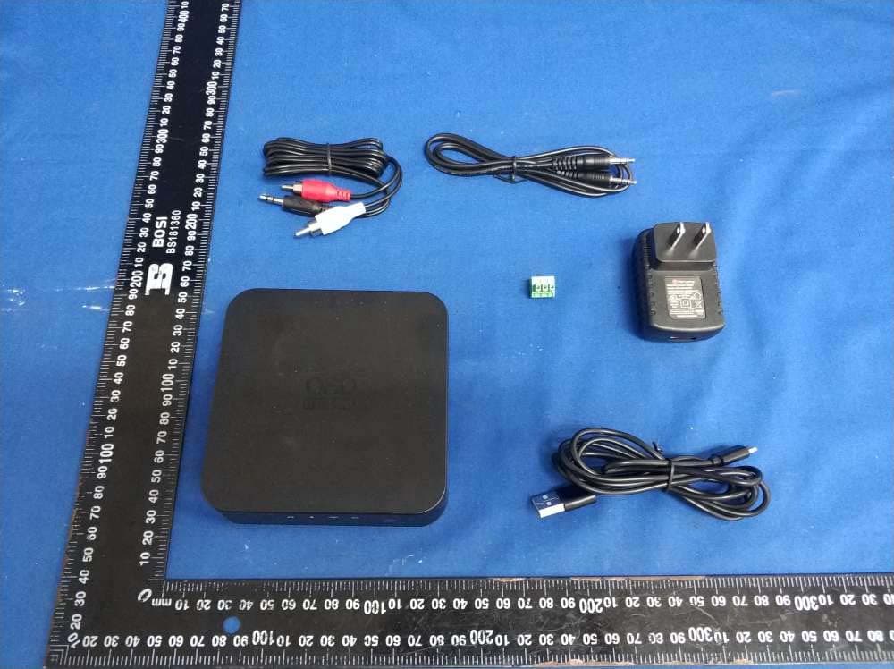
2A4UH-SRT1
Apr 24, 2022HI-FI DAC MUSIC STREAM MODULE
Equipment Class
DTS - Digital Transmission System