2A89O-ASPIREWLA-Spire Wireless Bluetooth headphone
Acezone ApS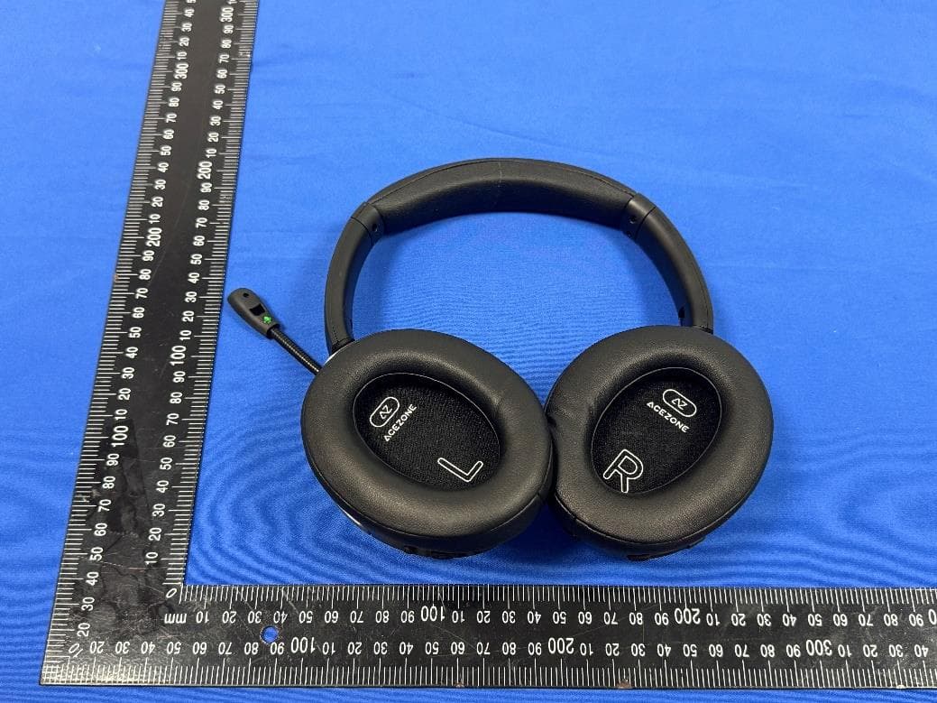
Click to zoom
Application Details
- Equipment Class
- DSS - Part 15 Spread Spectrum Transmitter
- Date of Grant
- Jun 19, 2024
- Application Purpose
- Original Equipment
- Date of Application
- Jun 19, 2024
- Equipment Note
- A-Spire Wireless Bluetooth headphone
- Frequency Range
- 2402.00000000 - 2480.00000000
- Company
- Acezone ApS
- Country
- Denmark
Documents & Files
Document Text
Text extracted from the exhibit documents filed with the FCC. Open a document above to read the original.
Users Manual
Single press . PRODUCT MANUAL NOISE CANCELLING Shortly press to switch between noise cancelling modes. While audio is playing, press and hold to switch between equalizer modes: 4 4 4 POWER ON/OFF To power the headset on or off, press and hold for 2 seconds. EQUALIZER CONTROL VOICE ASSISTANT 1 BOOM ARM MUSIC CONTROL PLAY/PAUSE MUSIC Shortly press to answer an incoming call, or to hang up during an ongoing call. Long press . 5 6 7 5 ADJUST VOLUME Shortly press for volume up, and shortly press for volume down. 6 7 5 PREVIOUS/NEXT TRACK Long press for next track, and long press for previous track. 6 7 PHONE CONTROL ANSWER/HANG UP 5 DECLINE INCOMING CALL 5 Double press to activate your smartphone’s given voice assistant. 4 HEADBAND ADJUSTMENT Lengthen the headband by pulling the ear cups away from the top of the headband, until the desired length is reached. Each adjustment step is signified by a clicking sound. To shorten the headband, push the ear cups back up into the top of the headband. Rotate the boom arm to a vertical or horizontal position to respectively mute or unmute the boom arm microphone. Ensure that the green microphone symbol on the boomarm microphone faces your mouth, and that the foam tip is securely in place. CONNECTION LED INDICATION Bluetooth pairing mode Connected Not connected Incoming call Charging Fully Charged CHARGE CONNECTION 8 8 9 9 REGULATORY AceZone ApS hereby declares that this product is in compliance with the essential requirements and other relevant provisions of Directive 2014/53/EU and all other applicable EU directive requirements. The complete declaration of conformity can be found at: www.acezone.io/compliance This product conforms to all applicable Electromagnetic Compatibility Regulations 2016 and all other applicable UK regulations. The complete declaration of conformity can be found at: www.acezone.io/compliance AceZone ApS hereby declares that this product is in compliance with the essential requirements per Radio Equipment Regulations 2017 and all other applicable UK regulations. The complete declaration of conformity can be found at: www.acezone.io/compliance Do not use this apparatus near water. Clean only with a dry cloth. Refer all servicing to qualified personnel. Servicing is required when the apparatus has been damaged in any way, such as power-supply cord or plug is damaged, liquid has been spilled or objects have fallen into the apparatus, the apparatus has been exposed to rain or moisture, does not operate normally, or has been dropped. Important Safety Instructions WARNINGS/CAUTIONS • Do NOT use the headset at a high volume for any extended period. – To avoid hearing damage, use your headset at a comfortable, moderate volume level. – Turn the volume down on your device before placing the headset in/on your ears, then turn the volume up gradually until you reach a comfortable listening level. • Do NOT use your headset while driving for phone calls or any other purpose. • Do NOT use the headset with noise canceling mode at any time the inability to hear surrounding sounds may present a danger to yourself or others, e.g., while riding a bicycle or walking in or near traffic, a construction site or railroad, etc., and follow applicable laws regarding headset use. – Turn the headset off, or use the headset with noise canceling off and adjust your volume, to ensure you can hear surrounding sounds, including alarms and warning signals. – Be aware of how sounds that you rely on as reminders or warnings may vary in character when using the headset, even with transparency mode. • Do NOT use the headset if they emit any loud unusual noise. If this happens, turn the headphones off and contact AceZone customer service. • Remove the headset immediately if you experience a warming sensation or loss of audio. • Do NOT use the headset as aviation communication headsets. Contains small parts which may be a choking hazard. Not suitable for children under age 3. This product contains magnetic material. Consult your physician on whether this might affect your implantable medical device. WARNINGS/CAUTIONS CONT. This symbol means the product must not be discarded as household waste, and should be delivered to an appropriate collection facility for recycling. Proper disposal and recycling helps protect natural resources, human health and the environment. For more information on disposal and recycling of this product, contact your local municipality, disposal service, or the shop where you bought this product. • Do NOT use mobile phone adapters to connect headset to airplane seat jacks, as this could result in injury or property damage due to overheating. • To reduce the risk of fire or electrical shock, do NOT expose this product to rain, liquids or moisture. • Do NOT expose this product to dripping or splashing, and do not place objects filled with liquids, such as vases, on or near the product. • Keep the product away from fire and heat sources. Do NOT place naked flame sources, such as lighted candles, on or near the product. • Use this product only with an agency approved LPS power supply which meets local regulatory requirements (e.g., UL, CSA, VDE, CCC). • Do NOT make unauthorized alterations to this product. • If the battery leaks, do not allow the liquid to come in contact with the skin or eyes. If contact is made, seek medical advice. • Do not expose products containing batteries to excessive heat (e.g. from storage in direct sunlight, fire or the like). • Do NOT wear while charging - One beep signals music mode. - Two beeps signal gaming mode. 1 1 USB - MAIN GAMING USE, and CHARGING For the best gaming performance and charging, connect using the USB Type-C cable. AUX - CONSOLE USE BLUETOOTH - CASUAL USE For consoles where a USB connection is not possible, connect using the AUX cable. 2 2 3 3 BATTERY STATUS While the headset is off, press and hold for 5 seconds to enter pairing mode. 1 While the headset is turned on, shortly press to get the headset b…
Text truncated - open the document above for the full version.
Attestation Statements
AceZone ApS Federal Communications Commission Authorization and Evaluation Division 7435 Oakland Mills Road Columbia, MD 21046 USA Date:6/27/2024 FCC ID: 2A89O-ASPIREWL Ref. #1: Attestation Statements Part 2.911(d)(5)(i) Filing AceZone ApS certifies that the equipment for which authorization is sought is not “covered” equipment prohibited from receiving an equipment authorization pursuant to section 2.903 of the FCC rules. Ref. #2: Attestation Statements Part 2.911(d)(5)(ii) Filing AceZone ApS certifies that, as of the date of the filing of the application, the applicant is not identified on the Covered List as an entity producing “covered” equipment. Applicant: AceZone ApS Address: Nordre Fasanvej 113, 2nd floor, 2000 Frederiksberg, Denmark Contact Person: Morten Birkmose Tel.: +4523297744 Email: [email protected] Sincerely, Signature:
Attestation Statements
Attestation Statements 6/27/2024 TO: Federal Communications Commission Authorization and Evaluation Division 7435 Oakland Mills Road Columbia, MD 21046, USA RE: Attestation Statements Part 2.911(d)(7) request for (FCC ID:2A89O-ASPIREWL) AceZone ApS, the undersigned, hereby authorize HOPEK CORPORATION INC to act as our designated U.S. agent for service of process, HOPEK CORPORATION INC accepts to maintain an agent for no less than one year after the grantee has terminated all marketing and importation or the conclusion of any Commission-related proceeding involving the equipment. HOPEK CORPORATION INC accepts the responsibility to act as designated U.S. agent for service of process. Applicant Information: Company name: AceZone ApS Contact Name: Morten Birkmose Address: Nordre Fasanvej 113, 2nd floor, 2000 Frederiksberg, Denmark Telephone No: +4523297744 Email: [email protected] FRN: 0033059197 Signature: Morten Birkmose U.S. Agent Information: Company Name: HOPEK CORPORATION INC Address: 4358 S BANNOCK ST ENGLEWOOD, CO 80110 United States FRN: 0034562900 Contact Name: Peter Davis Telephone No: 561-235-6113 Email: [email protected] Signature: Peter Davis
Cover Letter(s)
Effective Date: April 2, 2020 QSF 7.6.4-8 – Agent Authorization Letter Template Page 1 of 1 Revision Date: Revision: 0 AceZone ApS Date:6/20/2024 Product Model Number: H3WL FCC ID:2A89O-ASPIREWL To whom it may concern, Re: Product Certification Representative Authorization Letter We authorize QAI Laboratories Ltd. 3980 North Fraser Way, Burnaby B.C. Canada V5J 5K5 to act on our behalf on all matters concerning the above named equipment. This shall include the following: • Testing • Approval applications and procedures We declare that Shenzhen LGT Test Service Co., Ltd.. is allowed to forward all information related to the approval project to the applied certification body and to the notification entities and to discuss any issues concerning the approval application. Any and all acts carried out by Shenzhen LGT Test Service Co., Ltd.. on our behalf shall have the same effect as acts of our own. Signature: By: Morten Birkmose Contact Listed on FCC Wesbite Title: R&D manager Email: [email protected] On behalf of: AceZone ApS
Cover Letter(s)
AceZone ApS Office of Engineering Technology Federal Communications Commission 7435 Oakland Mills Road Columbia, MD 21046 USA Date: June 20, 2024 Subject; Request for Confidentiality FCC ID: 2A89O-ASPIREWL To Whom It May Concern, Pursuant to the provisions of the Commission’s rules Title 47 Sections §0.457 and §0.459, we are requesting the Commission to withhold the following attachment(s) as confidential documents from public disclosure indefinitely. These documents contain detailed system and equipment descriptions and are considered as proprietary information in operation of the equipment. The public disclosure of these documents might be harmful to our company and would give competitors an unfair advantage in the market. Schematic Diagram Block Diagram Parts List Operational Description Tune-up Procedure In additional to above mentioned documents, in order to comply with the marketing regulations in Title 47 CFR §2.803 and the importation rules in Title 47 CFR §2.1204, while ensuring that business sensitive information remains confidential until the actual marketing of newly authorized devices, we request Short Term Confidentiality of the following attachment(s); External Photos Test Setup Photos Internal Photos User Manual For 45 days, pursuant to Public Notice DA 04-1705. OR For 180 days pursuant to KDB 726920 D01. It is our understanding that all measurement test reports, FCC ID label format and correspondence during the certification review process cannot be granted as confidential documents and this information will be available for public review once the grant of equipment authorization is issued. Sincerely, Signature: Name: Morten Birkmose Title: R&D manager
Cover Letter(s)
第1页共10页 8010Chipantenna ForBluetooth/WLANApplications P/N:8010F245M01 Dimension(mm) L8.11±0.20 W1.03±0.20 T1.25±0.20 RAINInternationalTechnologyCo.,Ltd. TEL:13530576606 Add: 709, Building F, Yuxing Science and Technology Industrial Park, Nanchang Third Industrial Zone, Nanchang Community, Xixiang Street, Baoan District, Shenzhen 第2页共10页 PartNumberInformation RAIN 8010F245M01 ABCDEF AProductSeriesAntenna BDimensionLxW8.0X1.0mm(+-0.2mm) CMaterialHighKmaterial DWorkingFrequency2.4~2.5GHz EFeedingmodeMonopole&SingleFeeding FAntennatypeType=01 1.ElectricalSpecification Specification PartNumber8010F245M01 CentralFrequency2450MHz Bandwidth100(Min.)MHz ReturnLoss-10(Max)dB PeakGain3.45dBi Impedance50Ohm OperatingTemperature -40~+85°C MaximumPower4W ResistancetoSolderingHeats 10(@260°C) sec. PolarizationLinear AzimuthBeamwidthOmni-directional TerminationCu/Sn(Leadless) Remark:Bandwidth&PeakGainwasmeasuredunderevaluationboardofnextpage 第3页共10页 2.RecommendedPCBPattern EvaluationBoardDimension SuggestedMatchingCircuit Unit:mm 第4页共10页 LayoutDimensionsinClearancearea(Size=10.0*5.0mm) 50ohmtransmissionLine MatchingCircuit LayoutDimensionsinClearancearea(Size=10.0*3.0mm) 50ohmtransmissionLine MatchingCircuit FootPrint(Unit:mm) 第5页共10页 3.MeasurementResults ReturnLoss 第6页共10页 RadiationPattern Y X Z EfficiencyPeakGainDirectivity 2400MHz69.13%3.39dBi5.53dBi 2450MHz74.79%3.45dBi5.20dBi 2500MHz65.65%2.75dBi5.14dBi ChamberCoordinateSystem 第7页共10页 4.ReliabilityandTestCondictions ITEMREQUIREMENTSTESTCONDITION Solderability1.Wettingshallexceed90%coverage 2.Novisiblemechanicaldamage TEMP(°C) 230°C 4±1sec. 150 °C 60sec Pre-heatingtemperature:150°C/60sec. Soldertemperature:230±5°C Duration:4±1sec. Solder:Sn-Ag3.0-Cu0.5 Fluxforleadfree:rosin Solderheat Resistance 1.Novisiblemechanicaldamage 2.CentralFreq.change:within±6% TEMP(°C) 260°C 10±0.5sec. 150°C 60sec Pre-heatingtemperature:150°C/60sec. Soldertemperature:260±5°C Duration:10±0.5sec. Solder:Sn-Ag3.0-Cu0.5 Fluxforleadfree:rosin Component Adhesion (Pushtest) 1.Novisiblemechanicaldamage Thedeviceshouldbereflow soldered(230±5°Cfor10sec.)toatinned coppersubstrateAdynometerforce gaugeshouldbeappliedthesideofthe component.Thedevicemustwith-ST-F 0.5Kgwithoutfailureofthetermination attachedtocomponent. Component Adhesion (Pulltest) 1.Novisiblemechanicaldamage Insert10cmwireintotheremainingopen eyebend,theendsofevenwirelengths upwardandwindtogether. Terminalshallnotberemarkably damaged. Thermalshock 1.Novisiblemechanicaldamage 2.CentralFreq.change:within±6% +85 °C =>30±3min -40°C=>30±3min Testcycle:10cycles Thechipshallbestabilizedatnormal conditionfor2~3hoursbefore measuring. Resistanceto High Temperature 1.Novisiblemechanicaldamage 2.CentralFreq.change:within±6% 3.Nodisconnectionorshortcircuit. Temperature:85±5°C Duration:1000±12hrs Thechipshallbestabilizedatnormal conditionfor2~3hoursbefore measuring. Resistanceto Low Temperature 1.Novisiblemechanicaldamage 2.CentralFreq.change:within±6% 3.Nodisconnectionorshortcircuit. Temperature:-40±5°C Duration:1000±12hrs Thechipshallbestabilizedatnormal conditionfor2~3hoursbefore measuring. Humidity 1.Novisiblemechanicaldamage 2.CentralFreq.change:within±6% 3.Nodisconnectionorshortcircuit. Temperature:40±2°C Humidity:90%to95%RH Duration:1000±12hrs Thechipshallbestabilizedatnormal conditionfor2~3hoursbefore measuring. Phase Temperature(°C) Time(min) 1 +85±5°C 30±3 2 Room Temperature Within 3sec 3 -40±2°C 30±3 4 Room Temperature Within 3sec 第8页共10页 5.SolderingandMounting Mildlyactivatedrosinfluxesarepreferred.Theminimumamountofsolder canleadtodamagefromthestressescausedbythedifferencein coefficientsofexpansionbetweensolder,chipandsubstrate.The terminationsaresuitableforallwaveandre-flowsolderingsystems.Ifhand solderingcannotbeavoided,thepreferredtechniqueistheutilizationofhot airsolderingtools. ReflowSoldering PRE-HEATING 250~260 230 180 150 SOLDERING 10smax. NATURAL COOLING IronSoldering PRE-HEATINGSOLDERINGNATURAL COOLING 60~120s30~60s TIME(sec.) TIME(sec.) Recommendedtemperatureprofilesforre-flowsolderinginFigure1. Productsattachmentwithasolderingironisdiscouragedduetotheinherent processcontrollimitations.Intheeventthatasolderingironmustbe employedthefollowingprecautionsarerecommended. ‧Preheatcircuitandproductsto150°C ‧Nevercontacttheceramicwiththeirontip ‧Usea20wattsolderingironwithtipdiameterof1.0mm ‧280°Ctiptemperature(max) ‧1.0mmtipdiameter(max) ‧Limitsolderingtimeto3sec. within3s 350 150 Over60s Gradualcooling 300 T E M P E R A T U R E ( ° C ) T E M P E R A T U R E ( ° C ) 第9页共10页 6.PackagingInformation TapeSpecification: WAoBoKoPFEDD1PoP2t 16.0 ±0.30 1.30 ±0.10 8.30 ±0.10 1.40 ±0.10 4.00 ±0.10 7.50 ±0.10 1.75 ±0.10 1.50 ±0.10 0.00 ±0.10 4.00 ±0.10 2.00 ±0.10 0.30 ±0.05 ReelSpecification:(7’’,Φ180mm) TapeWidth(mm)A(mm)B(mm)C(mm)D(mm)Chip/Reel(pcs) 1616±1.060±213.5±0.5178±23000 第10页共10页 7.StorageandTransportationInformation StorageConditions Tomaintainthesolderabilityofterminalelectrodes: 1.Temperatureandhumidityconditions:-10~40°Cand30~70%RH. 2.Recommendedproductsshouldbeusedwithin6monthsfromthetime ofdelivery. 3.Thepackagingmaterialshouldbekeptwherenochlorineorsulfur existsintheair. TransportationConditions 1.Productsshouldbehandledwithcaretoavoiddamageor contaminationfromperspirationandskinoils. 2.Theuseoftweezersorvacuumpickupisstronglyrecommendedfor individualcomponents. 3.Bulkhandlingshouldensurethatabrasionandmechanicalshockare minimized.
External Photos
Page 1 of 3 Report No.: LGT24E092 Appendix - External Photographs of EUT Constructional Details FCC ID: 2A89O-ASPIREWL IC: 29781-ASPIREWL Model: H3WL Photo 1 Photo 2 Page 2 of 3 Report No.: LGT24E092 Photo 3 Photo 4 Page 3 of 3 Report No.: LGT24E092 Photo 5 Photo 6
ID Label/Location Info
Label A-Spire Wireless Bluetooth headphone Model: H3WL FCC ID: 2A89O-ASPIREWL IC: 29781-ASPIREWL 30mm Black font on a white label 15mm Label Bluetooth earphone Model: Acousy Z021 FCC ID: 2AMRE-ACOUSYZ020 IC: 32179-ACOUSYZ020 30mm Black font on a white label 15mm Label Bluetooth earphone Model: Acousy Z022 FCC ID: 2AMRE-ACOUSYZ020 IC: 32179-ACOUSYZ020 30mm Black font on a white label 15mm
Internal Photos
Page 1 of 8 Report No.: LGT24E092 Appendix - Internal Photographs of EUT Constructional Details FCC ID: 2A89O-ASPIREWL IC: 29781-ASPIREWL Model: H3WL Photo 1 Photo 2 Page 2 of 8 Report No.: LGT24E092 Photo 3 Photo 4 Page 3 of 8 Report No.: LGT24E092 Photo 5 Photo 6 Page 4 of 8 Report No.: LGT24E092 Photo 7 Photo 8 Page 5 of 8 Report No.: LGT24E092 Photo 9 Photo 10 BT ANT Page 6 of 8 Report No.: LGT24E092 Photo 11 Photo 12 Page 7 of 8 Report No.: LGT24E092 Photo 13 Photo 14 Page 8 of 8 Report No.: LGT24E092 Photo 15 Photo 16
RF Exposure Info
The test report is effective only with both signature and specialized stamp. This report shall not be reproduced except in full without the written approval of the Laboratory. The results in this report only apply to the tested sample. Shenzhen LGT Test Service Co., Ltd. Tel: 0755-89668180 E-mail:[email protected] Web: www.lgt-cert.com Room 205, Building 13, Zone B, Zhenxiong Industrial Park, No.177, Renmin West Road, Jinsha, Kengzi Street, Pingshan District, Shenzhen, Guangdong, China RF TEST REPORT Product Name: A-Spire Wireless Bluetooth headphone Model Name: H3WL FCC ID: 2A89O-ASPIREWL Issued For : AceZone ApS Nordre Fasanvej 113, 2nd floor, 2000 Frederiksberg, Denmark Issued By : Shenzhen LGT Test Service Co., Ltd. Room 205, Building 13, Zone B, Zhenxiong Industrial Park, No.177, Renmin West Road, Jinsha, Kengzi Street, Pingshan District, Shenzhen, Guangdong, China Report Number: LGT24E092HA02 Sample Received Date: May 21, 2024 Date of Test: May 21, 2024 – Jun. 13, 2024 Date of Issue: Jun. 13, 2024 Report No.: LGT24E092HA02 Page 2 of 9 TEST REPORT CERTIFICATION Applicant: AceZone ApS Address: Nordre Fasanvej 113, 2nd floor, 2000 Frederiksberg, Denmark Manufacture: AceZone ApS Address: Nordre Fasanvej 113, 2nd floor, 2000 Frederiksberg, Denmark Product Name: A-Spire Wireless Bluetooth headphone Trademark: Acezone Model Name: H3WL Sample Status: Normal APPLICABLE STANDARDS STANDARD TEST RESULTS FCC 47CFR §2.1093 KDB 447498 D01 General RF Exposure Guidance v06 PASS Prepared by: Approved by: Zane Shan Vita Li Engineer Technical Director Report No.: LGT24E092HA02 Page 3 of 9 TABLE OF CONTENTS 1 . GENERAL INFORMATION 5 1.1 GENERAL DESCRIPTION OF THE EUT 5 1.2 TEST LABORATORY 5 2 . FCC 47CFR §2.1093 REQUIREMENT 6 2.1 TEST STANDARDS 6 2.2 LIMIT 6 2.3 TEST RESULT 8 APPENDIX I - PHOTOGRAPHS OF EUT CONSTRUCTIONAL DETAILS 9 Report No.: LGT24E092HA02 Page 4 of 9 Revision History Rev. Issue Date Revisions 00 Jun. 13, 2024 Initial Issue Report No.: LGT24E092HA02 Page 5 of 9 1. GENERAL INFORMATION 1.1 GENERAL DESCRIPTION OF THE EUT Product Name: A-Spire Wireless Bluetooth headphone Trademark: Acezone Model Name: H3WL Series Model: N/A Model Difference: N/A Frequency Bands: Bluetooth: 2402-2480MHz Battery: Capacity: 850mAh Rated Voltage: 3.7V Hardware Version: V2 Software Version: V0.3.1 1.2 TEST LABORATORY Company Name: Shenzhen LGT Test Service Co., Ltd. Address: Room 205, Building 13, Zone B, Zhenxiong Industrial Park, No.177, Renmin West Road, Jinsha, Kengzi Street, Pingshan District, Shenzhen, Guangdong, China Accreditation Certificate A2LA Certificate No.: 6727.01 FCC Registration No.: 746540 CAB ID: CN0136 Report No.: LGT24E092HA02 Page 6 of 9 2. FCC 47CFR §2.1093 REQUIREMENT 2.1 TEST STANDARDS The limit for Maximum Permissible Exposure (MPE) specified in KDB 447498 D01 General RF Exposure Guidance v06 is followed. The gain of the antennas used in the product is extracted from the Antenna data sheets provided and also the maximum total power input to the antenna is measured. Through the Friis transmission formula and the maximum gain of the antenna, we can calculate the distance, away from the product, where the limit of MPE is reached. Although the Friis Transmission formula is far field assumption, the calculated result of that is an over-prediction for near field power density. It is taken as worst case to specify the safety range. 2.2 LIMIT Approximate SAR Test Exclusion Power Thresholds at Selected Frequencies and Test Separation Distances are illustrated in the following Table. Report No.: LGT24E092HA02 Page 7 of 9 The 1-g and 10-g SAR test exclusion thresholds for 100 MHz to 6 GHz at test separation distances ≤ 50 mm are determined by: [(max. power of channel, including tune-up tolerance, mW)/(min. test separation distance, mm)] • [√f(GHz)] ≤ 3.0 for 1-g SAR and ≤ 7.5 for 10-g extremity SAR,where f(GHz) is the RF channel transmit frequency in GHz. Power and distance are rounded to the nearest mW and mm before calculation The result is rounded to one decimal place for comparison The test exclusions are applicable only when the minimum test separation distance is ≤ 50 mm and for transmission frequencies between 100 MHz and 6 GHz. When the minimum test separation distance is < 5 mm, a distance of 5 mm is applied to determine SAR test exclusion. Report No.: LGT24E092HA02 Page 8 of 9 2.3 TEST RESULT Turn up Result Mode Turn up Power BT-GFSK -1±1dBm BT-π/4-DQPSK 1±1dBm BT-8DPSK 1.5±1dBm The MPE result of worst mode: RF Function Frequency (MHz) Max Turn up Power (dBm) Max Turn up Power (mW) Estimated SAR Limit Ratio Result BT 2441 2.50 1.78 0.556 3 0.185 Pass Note: 1. The estimated SAR≤ 3.0 for 1-g SAR, Separation distance ≤ 5mm, complies with the exemption requirements. Report No.: LGT24E092HA02 Page 9 of 9 APPENDIX I - PHOTOGRAPHS OF EUT CONSTRUCTIONAL DETAILS Note: Please see the attached H3WL_EUT Photos. ※※※※※END OF THE REPORT※※※※※
Test Report
The test report is effective only with both signature and specialized stamp. This report shall not be reproduced except in full without the written approval of the Laboratory. The results in this report only apply to the tested sample. Shenzhen LGT Test Service Co., Ltd. Tel: 0755-89668180 E-mail:[email protected] Web: www.lgt-cert.com Room 205, Building 13, Zone B, Zhenxiong Industrial Park, No.177, Renmin West Road, Jinsha, Kengzi Street, Pingshan District, Shenzhen, Guangdong, China RF TEST REPORT Product Name: A-Spire Wireless Bluetooth headphone Model Name: H3WL FCC ID: 2A89O-ASPIREWL IC: 29781-ASPIREWL Issued For : AceZone ApS Nordre Fasanvej 113, 2nd floor, 2000 Frederiksberg, Denmark Issued By : Shenzhen LGT Test Service Co., Ltd. Room 205, Building 13, Zone B, Zhenxiong Industrial Park, No.177, Renmin West Road, Jinsha, Kengzi Street, Pingshan District, Shenzhen, Guangdong, China Report Number: LGT24E092RF02 Sample Received Date: May 21, 2024 Date of Test: May 21, 2024 – Jun. 13, 2024 Date of Issue: Jun. 13, 2024 Report No.: LGT24E092RF02 Page 2 of 81 TEST REPORT CERTIFICATION Applicant: AceZone ApS Address: Nordre Fasanvej 113, 2nd floor, 2000 Frederiksberg, Denmark Manufacturer: AceZone ApS Address: Nordre Fasanvej 113, 2nd floor, 2000 Frederiksberg, Denmark Product Name: A-Spire Wireless Bluetooth headphone Trademark: Acezone Model Name: H3WL Sample Status: Normal APPLICABLE STANDARDS STANDARD TEST RESULTS FCC Part 15.247, Subpart C RSS-247 Issue 3, August 2023 RSS-Gen Issue 5, March 2021 ANSI C63.10-2013 PASS Prepared by: Approved by: Zane Shan Vita Li Engineer Technical Director Report No.: LGT24E092RF02 Page 3 of 81 Table of Contents Page 1. SUMMARY OF TEST RESULTS 7 1.1 TEST FACTORY 8 1.2 MEASUREMENT UNCERTAINTY 8 2. GENERAL INFORMATION 9 2.1 GENERAL DESCRIPTION OF THE EUT 9 2.2 DESCRIPTION OF THE TEST MODES 11 2.3 FREQUENCY HOPPING SYSTEM REQUIREMENTS 11 2.4 TABLE OF PARAMETERS OF TEST SOFTWARE SETTING 13 2.5 DESCRIPTION OF NECESSARY ACCESSORIES AND SUPPORT UNITS 13 2.6 EQUIPMENTS LIST 14 3. EMC EMISSION TEST 15 3.1 CONDUCTED EMISSION MEASUREMENT 15 3.2 RADIATED EMISSION MEASUREMENT 19 4. CONDUCTED SPURIOUS & BAND EDGE EMISSION 31 4.1 LIMIT 31 4.2 TEST PROCEDURE 31 4.3 TEST SETUP 32 4.4 EUT OPERATION CONDITIONS 32 4.5 TEST RESULTS 32 5. NUMBER OF HOPPING CHANNEL 33 5.1 LIMIT 33 5.2 TEST PROCEDURE 33 5.3 TEST SETUP 33 5.4 EUT OPERATION CONDITIONS 33 5.5 TEST RESULTS 33 6. AVERAGE TIME OF OCCUPANCY 34 6.1 LIMIT 34 6.2 TEST PROCEDURE 34 6.3 TEST SETUP 34 6.4 EUT OPERATION CONDITIONS 34 6.5 TEST RESULTS 34 7. HOPPING CHANNEL SEPARATION MEASUREMEN 35 7.1 LIMIT 35 7.2 TEST PROCEDURE 35 Report No.: LGT24E092RF02 Page 4 of 81 7.3 TEST SETUP 35 7.4 EUT OPERATION CONDITIONS 35 7.5 TEST RESULTS 35 8. BANDWIDTH TEST 36 8.1 LIMIT 36 8.2 TEST PROCEDURE 36 8.3 TEST SETUP 36 8.4 EUT OPERATION CONDITIONS 36 8.5 TEST RESULTS 36 9. OUTPUT POWER TEST 37 9.1 LIMIT 37 9.2 TEST PROCEDURE 37 9.3 TEST SETUP 37 9.4 EUT OPERATION CONDITIONS 37 9.5 TEST RESULTS 37 10. ANTENNA REQUIREMENT 38 10.1 STANDARD REQUIREMENT 38 10.2 EUT ANTENNA 38 11. FREQUENCY STABILITY 39 11.1 LIMITS OF FREQUENCY STABILITY MEASUREMENT 39 11.2 TEST PROCEDURE 39 11.3 TEST RESULT 39 APPENDIX I - TEST RESULTS 40 DUTY CYCLE 40 MAXIMUM AVERAGE CONDUCTED OUTPUT POWER 44 MAXIMUM PEAK CONDUCTED OUTPUT POWER 44 -20DB BANDWIDTH 45 OCCUPIED CHANNEL BANDWIDTH 49 CARRIER FREQUENCIES SEPARATION 53 BAND EDGE 57 BAND EDGE(HOPPING) 62 CONDUCTED RF SPURIOUS EMISSION 67 NUMBER OF HOPPING CHANNEL 74 DWELL TIME 76 FREQUENCY STABILITY 79 Report No.: LGT24E092RF02 Page 5 of 81 APPENDIX II - TEST SETUP PHOTOS 80 APPENDIX II - PHOTOGRAPHS OF EUT CONSTRUCTIONAL DETAILS 81 Report No.: LGT24E092RF02 Page 6 of 81 Revision History Rev. Issue Date Contents 00 Jun. 13, 2024 Initial Issue Report No.: LGT24E092RF02 Page 7 of 81 1. SUMMARY OF TEST RESULTS Test procedures according to the technical standards: KDB 558074 D01 15.247 Meas Guidance v05r02. FCC Part 15.247, Subpart C RSS-247 Issue 3 Standard Section Test Item Judgment Remark 15.207 RSS-Gen (8.8&7.2) Conducted Emission PASS -- 15.247(a)(1) RSS-247 (5.1) Hopping Channel Separation PASS -- 15.247(a)(1)&(b)(1) RSS-247 (5.1) Output Power PASS -- 15.209 RSS-Gen (8.9&8.10) Radiated Spurious Emission PASS -- 15.247(d) RSS-247 (5.5) Conducted Spurious & Band Edge Emission PASS -- 15.247(a)(1)(iii) RSS-247 (5.1) Number of Hopping Frequency PASS -- 15.247(a)(1)(iii) RSS-247 (5.1) Dwell Time PASS -- 15.247(a)(1) RSS-247 (5.1) Bandwidth PASS -- 15.205 RSS-Gen (8.9&8.10) Restricted bands of operation PASS -- Part 15.247(d)/part 15.209(a) RSS-247 (5.5) RSS-Gen (8.9&8.10) Band Edge Emission PASS -- 15.203 RSS-Gen (6.8) Antenna Requirement PASS -- RSS-Gen (6.11&8.11) Frequency Stability PASS -- NOTE: (1) ‘N/A’ denotes test is not applicable in this Test Report. (2) All tests are according to ANSI C63.10-2013. (3) When the EUT is charging, the Bluetooth function is automatically turned off. Report No.: LGT24E092RF02 Page 8 of 81 1.1 TEST FACTORY Company Name: Shenzhen LGT Test Service Co., Ltd. Address: Room 205, Building 13, Zone B, Zhenxiong Industrial Park, No.177, Renmin West Road, Jinsha, Kengzi Street, Pingshan District, Shenzhen, Guangdong, China Accreditation Certificate A2LA Certificate No.: 6727.01 FCC Registration No.: 746540 CAB ID: CN0136 1.2 MEASUREMENT UNCERTAINTY The reported uncertainty of measurement y ± U, where expended uncertainty U is based on a standard uncertainty multiplied by a coverage factor of k=2, providing a level of confidence of approximately 95 %. No. Item Uncertainty 1 RF output power, conducted ±0.68dB 2 Unwanted Emissions, conducted ±2.988dB 3 All emissions, radiated 9K-30MHz ±2.84dB 4 All emissions, radiated 30M-1GHz ±4.39dB 5 All emissions, radiated 1G-6GHz ±5.10dB 6 All emissions, radiated>6G ±5.48dB 7 Conducted Emission (9KHz-150KHz) ±2.79dB 8 Conducted Emission (150KHz-30MHz) ±2.80dB 9 Emission Bandwidth ±3.2 % Note: The measurement uncertainty is not included in the test r…
Text truncated - open the document above for the full version.
Test Setup Photos
Page 1 of 2 Report No.: LGT24E092 Appendix - Test Setup photos Set-up for Radiated Spurious Emission, Below 1GHz Set-up for Radiated Spurious Emission, Above 1GHz Page 2 of 2 Report No.: LGT24E092 Set-up for Conducted Emission
Contact Information
Applicant
Morten Birkmose(R&D manager)
Technical Contact
Test Firm
Shenzhen LGT Test Service Co., Ltd.Wen Wen
[email protected]0755-89668180
Technical Specifications
| # | Rule Parts | Frequency Range | Power Output |
|---|---|---|---|
| 1 | 15C | 2.40 GHz - 2.48 GHz | 1.60 mW |
Other Applications from Acezone ApS
2A89O-DW01B
Jul 03, 2024A-Spire Wireless Bluetooth headphone
Equipment Class
DSS - Part 15 Spread Spectrum Transmitter
2A89O-ASPIRE
Jan 09, 2023Wireless Bluetooth Headphones
Equipment Class
DSS - Part 15 Spread Spectrum Transmitter