2A9Q9-M2288Q-17700mAh Wireless Power Bank with TWs earphone
ShenZhen Zhongyi Technology CO., Ltd.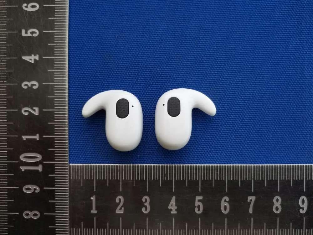
Click to zoom
Application Details
- Equipment Class
- DSS - Part 15 Spread Spectrum Transmitter
- Date of Grant
- Feb 05, 2026
- Application Purpose
- Original Equipment
- Equipment Note
- 7700mAh Wireless Power Bank with TWs earphone
- Frequency Range
- 2402.00000000 - 2480.00000000
- Country
- China
Documents & Files
Document Text
Text extracted from the exhibit documents filed with the FCC. Open a document above to read the original.
Users Manual
Power Button Magnetic Wireless Charging Surface Type-C Input/Output Port LCD Display Power Case Earbuds Charging LED Sensor READ ALL INSTRUCTIONS CAREFULLY BEFORE USE AND KEEP THIS MANUAL IN THE BOX • 7700mAh Wireless Power Bank with TWS Earbuds(x1) • Instruction Manual(x1) • Magnetic lron Ring(x1) • Charging Cable(x1) SAFETY PRECAUTIONS • This product is NOT a toy, keep away from children and pets. • Only use the product according to the instructions in this manual. Never use the product for anything other than its intended purpose. • Do not open this product or attempt to repair the unit yourself if it is not working properly. Doing so risks fire, shock or injury. • When not in use, the product should be stored in a dry, cool location, away from sources of water or heat. • Do not expose product or charging cable to extreme temperatures (heat or cold), open flames, humid or wet conditions. • Do not submerge in water. Do not use in a location where the product or charging cable could fall into liquid. • Unplug the charging cable when not in use. Do not pull the charging cable to disconnect, or use the cable as a handle. • Do not use if the product or charging cable is damaged. If the product or charging cable is damaged, it MUST be serviced or replaced by the manufacturer or its service agent before using again. • Do not over charge the battery. Unplug the device when charging is complete. • This product contains a built-in lithium-ion polymer battery and should not be disposed of with regular household waste. Please consult your local hazardous waste agency or waste service provide with instruction on how to dispose of this product. • Any accessories attached to the back of your device can reduce wireless charging efficiency and may lead to overheating. Please remove all attachments before using the wireless power bank. •The strong magnetic fields produced by the neodymium magnets in this device can damage items such as televisions, computers, monitors, credit and bank cards, diskettes and other data storage media, video tapes, mechanical watches, hearing aids, loudspeakers, and VCRs. Pacemakers and other electronic body implants may be damaged or switched into “test mode” when exposed to strong magnetic forces. Maintain a minimum distance of 3 feet . PRODUCT DIAGRAMS WIRELESS CHARGING (Continued) For all other Qi Wireless enabled devices Magnetic Ring Application • Consult your device’s manual to locate the correct position of your device’s Qi Wireless charging coil. • Using the magnetic iron ring (included), remove the sticker lining from the back of the ring and adhere to the the wireless charging area on the back of your device or phone case. After the magnetic ring has been applied to your device or phone case, place the device against the magnetic wireless charging surface. The will begin charging automatically. • If your device does not begin charging, try repositioning your device on the wireless charging surface. You may need to remove the case on your device to charge properly. • Remove your device from the wireless charging surface when it is fully charged Safety Note: Wireless charging will automatically power off when the wireless charging surface is overheated or when a metal object, such as a coin, is place on the wireless charging surface. USING EARBUDS 1.Charging Earbuds • Place the earbuds securely into the charging case. The earbuds will begin charging automatically and the LED light on each earbud will turn red. • When fully charged, the LED on the earbuds will briefly turn blue and then off. 2. Power On • Remove the earbuds from the charging case. You will hear “Power On”. • If the earbuds have previously been paired, are outside of the case and are powered off, simply press and hold each earbud’s touch sensor for 5 seconds to turn them on. 3. Pairing Both Earbuds • Remove one or both earbuds from the case, one earbud will blink red and blue, indicating it is ready to pair. • Upon removal, you will hear the voice prompt “Power On”. • You will hear the voice prompt “Pairing” when the earbud(s) are ready to be paired with your device. • Open your device’s Bluetooth settings and select “M2288Q.” • Once connected, you will hear the voice prompt “Connected,” and you can begin enjoying your audio. Notes: • In pairing search mode, both earbuds will automatically power off if no pairing occurs within 5 minutes. • Earbuds will automatically reconnect after being previously connected to a device. 4. Power Off • In pairing search mode, both earbuds will automatically power off if no pairing occurs within 5 minutes. • While paired with your device, you may do any of the following: • Press and hold one or both earbuds’ touch sensors for 5 seconds to power them off. You will hear the voice prompt “Power Off.” • Alternatively, simply place the earbuds back into the charging case. TECH SPECIFICATIONS Battery Capacity: 7700mAh/3.85V/29.65Wh/Power Bank Battery Capacity: 30mAh/3.7V/0.11Wh/Earbuds Output For Power Case: 5V ⎓0.2A Type-C Input: 5V ⎓3A 9V⎓2A 12V⎓1.5A 18W Max Type-C Output: 5V ⎓3A 9V⎓2.22A 10V⎓2.25A 12V⎓1.67A 22.5W Max Wireless Output: 5W/7.5W/10W/15W FCC INFORMATION This device complies with Part 15 of the FCC Rules. Caution: Any changes or modifications not expressly approved could void the user's authority to operate the equipment. Note: This equipment has been tested and found to comply with the limits for a Class B digital device, pursuant to Part 15 of the FCC Rules. These limits are designed to provide reasonable protection against harmful interference in a residential installation. This equipment generates, uses and can radiate radio frequency energy and, if not installed and used in accordance with the instructions, may cause harmful interference to radio communications. However, there is no guarantee that interference will not occur in a particular installation. If this equipment does cause harmful interference to radio or television reception, which can be dete…
Text truncated - open the document above for the full version.
Attestation Statements
Rev 1/26/2023 ShenZhen Zhongyi Technology CO., Ltd. Federal Communications Commission Authorization and Evaluation Division 7435 Oakland Mills Road Columbia, MD 21046 USA Date: February 1, 2026 Ref: Attestation Statements Part 2.911(d)(5)(i) Filing FCC ID: 2A9Q9-M2288Q-1 [ShenZhen Zhongyi Technology CO., Ltd.] (“the applicant”) certifies that the equipment for which authorization is sought is not “covered” equipment prohibited from receiving an equipment authorization pursuant to section 2.903 of the FCC rules. [ShenZhen Zhongyi Technology CO., Ltd.] (“the applicant”) certifies that the equipment for which authorization is sought does not include cybersecurity or anti-virus software produced or provided by Kaspersky Lab, Inc. or any of its successors and assignees, including equipment with integrated Kaspersky Lab, Inc. (or any of its successors and assignees) cybersecurity or anti-virus software pursuant to DA-24- 886 and KDB 986446 D01 Covered Equipment Guidance section B(2a). Device is inherently compliant based on hardware limitations or software controls. or A Software Bill of Materials (SBOM) is provided to the TCB for review, and The end-user or third parties cannot install additional software on this device. Sincerely, Name: Merry Yu Signature: Rev 1/26/2023 ShenZhen Zhongyi Technology CO., Ltd. Federal Communications Commission Authorization and Evaluation Division 7435 Oakland Mills Road Columbia, MD 21046 USA Date: February 1, 2026 Ref: Attestation Statements Part 2.911(d)(5)(ii) Filing FCC ID: 2A9Q9-M2288Q-1 [ShenZhen Zhongyi Technology CO., Ltd.] (“the applicant”) certifies that, as of the date of the filing of the application, the applicant is not identified on the Covered List (as a specifically named entity or any of its subsidiaries or affiliates) as an entity producing “covered” equipment. Sincerely, Name: Merry Yu Signature:
Attestation Statements
ShenZhen Zhongyi Technology CO., Ltd. U.S. Agent Letter of Attestation To: Federal Communications Commission 7435 Oakland Mills Road, Columbia, MD 21046, USA Date: January 27, 2026 Ref: Attestation Statement – Part 2.911(d)(7) filing FCC ID: 2A9Q9-M2288Q-1 ShenZhen Zhongyi Technology CO., Ltd. (“the applicant”) certifies that, as of the date of the filing of the application, CLF Import and Export Limited (“the agent”) is our designated U.S. agent for service of process for the above reference FCC ID. The applicant accepts to maintain an agent for service of process in the United States for no less than one year after either the grantee has permanently terminated all marketing and importation of the applicable equipment within the U.S., or the conclusion of any Commission-related administrative or judicial proceeding involving the equipment, whichever is later. The applicant further acknowledges it is our responsibility to inform the FCC whenever the agent information changes. CLF Import and Export Limited ("the agent) understand it is the agent's obligation to accept service of process in the United States for matters related to the applicable equipment, and at the physical U.S. address and email address. Designated U.S. Agent Company Name: CLF Import and Export Limited FRN: 0033489683 Address: 1312 17th Street #692, Denver, CO 80202, United States Signature: Contact Person: David Chen Tel: +1 949 254 2565 Email: [email protected] Applicant Company Name: ShenZhen Zhongyi Technology CO., Ltd. FRN: 0033187147 Address: Room 401, No.4 Road One, Shangxue Science and Technology City, Xinxue Community, Bantian Street, Longgang District, Shenzhen, China Signature: Contact Person: Merry Yu Tel: 0755-89501773 Email: [email protected]
Attestation Statements
ShenZhen Zhongyi Technology CO., Ltd. Federal Communications Commission Authorization and Evaluation Division 7435 Oakland Mills Road Columbia, MD 21046 Date: February 1, 2026 SUBJECT: FCC SDoC declaration for FCC ID: 2A9Q9-M2288Q-1 To Whom It May Concern: I, the undersigned, hereby states this equipment has been tested and found to comply with the limits for a Class B digital device, pursuant to part 15 of the FCC Rules, and will apply the Supplier's Declaration of Conformity procedure to the class B computer peripheral portion of this composite device. I understand the following FCC requirements: 1. Devices subject to the SDoC procedure are required to be tested to show compliance with the FCC technical regulations by a recognized accredited testing laboratory. The testing laboratory must be accredited by a Commission approved accreditation body or designated under the terms of a government-to-government Mutual Recognition Agreement (MRA). A listing of those accredited testing laboratories that have been recognized by the Commission is published on the FCC Webpage: https://apps.fcc.gov/oetcf/eas/reports/TestFirmSearch.cfm (Select the "accredited" option to search for FCC recognized accredited test firms.) 2. Pt 2.1077 contains the list of information that must be included in the Supplier's Declaration of Conformity, which must be supplied with each product sold. The SDoC compliance info shall be included in the User’s Manual or as a separate sheet. The info must contain the name, address, and phone number of the responsible party, which must be located within the United States. According to 2.909(b), the responsible party is either the Manufacturer or if the product is imported the Importer. Regards, ShenZhen Zhongyi Technology CO., Ltd. Signature: ------------------------------- Name: Merry Yu
Cover Letter(s)
ShenZhen Zhongyi Technology CO., Ltd. Federal Communications Commission Authorization and Evaluation Division 7435 Oakland Mills Road Columbia, MD 21046 Date: February 1, 2026 SUBJECT: FCC Application for FCC ID: 2A9Q9-M2288Q-1 To Whom It May Concern: We, the undersigned, hereby authorize Lahm Peng at Shenzhen CCUT Quality Technology Co., Ltd. on our behalf, to apply to the Federal Communications Commission on our equipment. Any and all acts carried out by Lahm Peng at Shenzhen CCUT Quality Technology Co., Ltd. on our behalf shall have the same effect as acts of our own. This is to advise that we are in full compliance with the Anti- Drug Abuse Act. We, the applicant, are not subject to a denial of federal benefits pursuant to Section 5301 of the Anti-Drug Act of 1988, 21 USC853a, and no party to the application is subject to a denial of federal benefits pursuant to that section. Regards, Name: Merry Yu Signature:
Cover Letter(s)
Rev 11/20/07 ShenZhen Zhongyi Technology CO., Ltd. Federal Communications Commission Authorization and Evaluation Division Confidentiality Request regarding application for certification of FCC ID: 2A9Q9-M2288Q-1 Pursuant to Sections 0.457 and 0.459 of the Commission’s Rules, we hereby request confidential treatment of information accompanying this application as outlined below: Exhibit Type File Name (Block Diagram, Schematics, Operational Description) (Block Diagram.pdf, Schematics.pdf, Operational Description.pdf) The above materials contain trade secrets and proprietary information not customarily released to the public. The public disclosure of these materials may be harmful to the applicant and provide unjustified benefits to its competitors. The applicant understands that pursuant to Section 0.457 of the Rules, disclosure of this application and all accompanying documentation will not be made before the date of the Grant for this application. Pursuant to DA04-1705 June 15, 2004 of the Commission’s public notice, we also request temporary confidential treatment of information accompanying this application as outlined below: Exhibit Type File Name For 45 days, pursuant to Public Notice DA 04-1705. OR For 180 days pursuant to KDB 726920 D01. It is our understanding that all measurement test reports, FCC ID label format and correspondence during the certification review process cannot be granted as confidential documents and this information will be available for public review once the grant of equipment authorization is issued. Sincerely, Name: Merry Yu Signature:
Cover Letter(s)
ShenZhen Zhongyi Technology CO., Ltd. Model Difference Statement DATE: January 27, 2026 FCC ID: 2A9Q9-M2288Q-1 Dear Sir/Madam, Added models QC2288BK, QC2288WT of the original product M2288Q The color of appearance and model name of series models listed are different from the main model, but the circuit and the electronic construction are the same, declared by the manufacturer. Sincerely, Name: Merry Yu Title: Manager Company name: Iphoenix Technology Corp Address: Room 401, No.4 Road One, Shangxue Science and Technology City, Xinxue Community, Bantian Street, Longgang District, Shenzhen, China
External Photos
Report No: SSP26010246-1E FCC ID: 2A9Q9-M2288Q-1 Annex of Test Report Annex A. EUT External Photos Model: M2288Q EUT View 1 EUT View 2 Report No: SSP26010246-1E FCC ID: 2A9Q9-M2288Q-1 Annex of Test Report EUT View 3 EUT View 4 Report No: SSP26010246-1E FCC ID: 2A9Q9-M2288Q-1 Annex of Test Report EUT View 5 EUT View 6 Report No: SSP26010246-1E FCC ID: 2A9Q9-M2288Q-1 Annex of Test Report EUT View 7 EUT View 8
ID Label/Location Info
Report No: SSP26010246-1E FCC ID: 2A9Q9-M2288Q-1 Annex of Test Report Annex D. Label and Information FCC Label Sample FCC Labe Size: 0.5cm x 0.5cm FCC Label Specifications Text is Black in color and is justified. Labels are printed in indelible ink on permanent adhesive backing or silk-screened onto the EUT or shall be affixed at a conspicuous location on the EUT. Where the EUT is constructed in two or more sections connected by wires and marketed together, the above statement is required to be affixed only to the main control unit. When the EUT is so small or for such use that it is not practicable to place the statement on it, the above information shall be placed in a prominent location in the instruction manual or pamphlet supplied to the user or, alternatively, shall be placed on the container in which the device is marketed. FCC Label Location Label Location
Internal Photos
Report No: SSP26010246-1E FCC ID: 2A9Q9-M2288Q-1 Annex of Test Report Annex B. EUT Internal Photos EUT Internal View 1 EUT View 2 Report No: SSP26010246-1E FCC ID: 2A9Q9-M2288Q-1 Annex of Test Report EUT View 3 EUT View 4 SMD ANT SMD ANT Report No: SSP26010246-1E FCC ID: 2A9Q9-M2288Q-1 Annex of Test Report EUT View 5
RF Exposure Info
FCC ID: 2A9Q9-M2288Q-1 RF Exposure Evaluation According to KDB 447498 D01 General RF Exposure Guidance v06 and part 2.1093,Unless specifically required by the published RF exposure KDB procedures, standalone 1-g head or body and 10-g extremity SAR evaluation for general population exposure conditions, by measurement or numerical simulation, is not required when the corresponding SAR Test Exclusion Threshold condition(s), listed below, is (are) satisfied. For 100 MHz to 6 GHz and test separation distances ≤ 50 mm, the 1-g and 10-g SAR test exclusion thresholds are determined by the following: [(max. power of channel, including tune-up tolerance, mW) / (min. test separation distance, mm)] · [√f(GHz)] ≤ 3.0 for 1-g SAR, and ≤ 7.5 for 10-g extremity SAR, where f(GHz) is the RF channel transmit frequency in GHz Power and distance are rounded to the nearest mW and mm before calculation The result is rounded to one decimal place for comparison Here, The device has been evaluated to meet general RF exposure requirement. The device can be used in portable exposure condition without restriction. For BR+EDR Max Conducted Power(dBm) Tune-up Power(dBm) Max Tune-up Power(dBm) Max Power(mW) Frequency(MHz) Min. distance(mm) Calc. thresholds limit 3.2 3(±1) 4 2.51 2441 5 0.784309 3.0 So a SAR test is not required
Test Report
SymbolsLWTA Dimensions 1.60±0.200.80±0.200.80±0.200.30±0.10 NumberTerminalName ① INPUT ② NC Dimensions(Unit: mm) w ①② ( Side View) ( Bottom View) ( Top View) A T L Shenzhen HanyangAntenna Design Co. Ltd. 1.Bluetooth 2.Dual-band WLAN 3.ISM and UWB 1.Surfacemountedelementwithasmalldimensionof1.6×0.8×0.8mmmeetfutureminiaturizationtrend. 2.EmbeddedandLTCC(lowtemperatureco-firedceramic)technologyisabletointegratewithsystemdesign aswellasbeatifyingthehousingoffinalproduct. 3.Miniaturization,wideband,highstability,lowESR,andlowtolerance. 4.Dual-bandresonancesinthedominantandharmonicmodesenablesmultibandoperations. 5.Novelground-radiationtechniqueenablesradiationfromboththeantennaandthegroundplane. Shenzhen BaoanDistrict Qianjin2 Road BaoYunda logistics information building 12A10 tel:0755-23069700 Features: Applications: RF chip ANT chipANT pattern PCB ground Mode-2 Mode-1 P/N: HY160808 SRF09 ShenzhenHanyangAntennaDesignCo.Ltd.haspossessionofproprietaryinformationprovidedinthis reportandthisproprietaryinformationshallbekeptinstrictconfidenceandnotdisclosedtoanyperson orfirmwithoutthepriorwrittenconsentofShenzhenHanyangAntennaDesignCo.Ltd. Page1 Layout-1 (3.5mm×6.5mm) ShenzhenHanyangAntennaDesignCo.Ltd.haspossessionofproprietaryinformationprovidedinthis reportandthisproprietaryinformationshallbekeptinstrictconfidenceandnotdisclosedtoanyperson orfirmwithoutthepriorwrittenconsentofShenzhenHanyangAntennaDesignCo.Ltd. Page2 1.5 1 3.5 2.5 0201 footprint (E1) 0201 footprint (E2) 0603 footprint (ANT) RF Input/Output 6.5 0.5 0.5 0.5 1.5 3.5 2.5 0201 footprint (E3) 6.5 Top layer: Bottom layer: 0.5 0.5 RF chip E1 E3 E2 ANT Equivalentcircuit: P/N: HY160808 SRF09 Shenzhen HanyangAntenna Design Co. Ltd. Shenzhen BaoanDistrict Qianjin2 Road BaoYunda logistics information building 12A10 tel:0755-23069700 2.5 0201 footprint 0603 footprint 10 0.5 1.5 0201 footprint 1.5 3 2.5 10 1.5 2 0.5 0201 footprint Layout-2 (1.5mm×10mm) Top layer: Bottom layer: P/N: HY160808 SRF09 Shenzhen HanyangAntenna Design Co. Ltd. Shenzhen BaoanDistrict Qianjin2 Road BaoYunda logistics information building 12A10 tel:0755-23069700 ShenzhenHanyangAntennaDesignCo.Ltd.haspossessionofproprietaryinformationprovidedinthis reportandthisproprietaryinformationshallbekeptinstrictconfidenceandnotdisclosedtoanyperson orfirmwithoutthepriorwrittenconsentofShenzhenHanyangAntennaDesignCo.Ltd. Page3 RF Input/Output ElectricalCharacteristics: CharacteristicCurves: FeatureSpecification 1 Centralfrequency2.45GHz 2 Bandwidth>150MHz 3 Peak gain2.78dBi 4 VSWR<2 5 PolarizationLinear 6 AzimuthbeamwidthOmnidirectional 7 Impedance50Ω P/N: HY160808 SRF09 Shenzhen HanyangAntenna Design Co. Ltd. Shenzhen BaoanDistrict Qianjin2 Road BaoYunda logistics information building 12A10 tel:0755-23069700 ShenzhenHanyangAntennaDesignCo.Ltd.haspossessionofproprietaryinformationprovidedinthis reportandthisproprietaryinformationshallbekeptinstrictconfidenceandnotdisclosedtoanyperson orfirmwithoutthepriorwrittenconsentofShenzhenHanyangAntennaDesignCo.Ltd. Page5 RadiationPattern: Y-ZPlaneX-ZPlane coordinates: 深圳市宝安区前进二路宝运达物流信息大厦12A10/12A11 青岛市崂山区松岭路399号海信产业园A1号楼606 电话:0755-23069700 传真:0755-23069700 HanyangAntennaDesignCo.Ltd.haspossessionofproprietaryinformationprovidedinthisreportand thisproprietaryinformationshallbekeptinstrictconfidenceandnotdisclosedtoanypersonorfirm withoutthepriorwrittenconsentofHanyangAntennaDesignCo.Ltd. Page5 RadiationPerformance: P/N: HY160808 SRF07, HY160808 SRF08,HY160808 SRF09 深圳汉阳天线设计有限公司 Shenzhen Hanyang Antenna Design Co. Ltd. X-YPlane Frequency 2400MHz2450MHz2500MHz Avg.gain-1.92-1.35-1.56 Peakgain1.792.782.66 Efficiency74.5580.2576.98 Temperature:40±2°C Humidity:90~95%RH Duration:500h Recovery conditions:Room temperature Recovery Time:24h (Class1) or 48h (Class2) Test Temperature Operating Temperature Temperature RelativeHumidity 25°C±5°C -25°C~+125°C 5~40°C 20~70% Notenoughsolder Weak holding forcemay cause bad connection between the chipandPCB. RecommendedSolderingAmounts The optimal solder fillet amounts forre-flowsoldering 天线厚度 以下 The optimal solder fillet amounts for wavesoldering DependabilityTest Too much solder Cracks tend to occur due to large stress. MoistureProof OptimumSolderAmount forReflowSoldering Solderability At least 95% of the terminal electrode is covered by newsolder. Preheating conditions:80 to 120°C;10~30s. Solder Tem p e r at u r e :2 3 5 ±5°CDuration:2 ±0.5s , Solder Tempe r ature:24 5±5°CDu rat ion:2±0.5s P/N: HY160808 SRF09 Shenzhen HanyangAntenna Design Co. Ltd. Shenzhen BaoanDistrict Qianjin2 Road BaoYunda logistics information building 12A10 tel:0755-23069700 ShenzhenHanyangAntennaDesignCo.Ltd.haspossessionofproprietaryinformationprovidedinthis reportandthisproprietaryinformationshallbekeptinstrictconfidenceandnotdisclosedtoanyperson orfirmwithoutthepriorwrittenconsentofShenzhenHanyangAntennaDesignCo.Ltd. Page6 10±1S AppliedForce:5NDuration:10±1S Preheating conditions: up-category temperature, 1h Recovery time:24±1h InitialMeasurement Cycling Times: 5 times, 1 cycle, 4steps: Preheating80to120°C;10~30s.SolderTemperature:235±5°C;Duration:2±0.5s;SolderTemperature:245±5°C Duration:2±0.5s;Preheating100to200°C;10±2min. SolderTemperature:265±5°C;Duration:10±1s Cleanthecapacitorwithsolventandexamineitwitha10X(min.)microscope. RecoveryTime:24±2h Recoverycondition:Roomtemperature Test Board: Al 2 O 3 orPCBWarp:1mm Speed:0.5mm/sec. Unit:mm Themeasurementshouldbemadewiththeboardinthe bendingposition. Resistance to Soldering Heat ResistancetoFlexureofSubstrate Temperature CycleTest P/N: HY160808 SRF09 Shenzhen HanyangAntenna Design Co. Ltd. Shenzhen BaoanDistrict Qianjin2 Road BaoYunda logistics information building 12A10 tel:0755-23069700 ShenzhenHanyangAntennaDesignCo.Ltd.haspossessionofproprietaryinformationprovidedinthis reportandthisproprietaryinformationshallbekeptinstrictconfidenceandnotdisclosedtoanyperson orfirmwithoutthepriorwrittenconsentofShenzhenHanyangAntennaDesignCo.Ltd. Page7 StageTemperatur…
Text truncated - open the document above for the full version.
Test Report
Report No: SSP26010246-1E FCC Test Report Page 1 of 69 FCC TEST REPORT FCC ID: 2A9Q9-M2288Q-1 Report No. : SSP26010246-1E Applicant : ShenZhen Zhongyi Technology CO., Ltd. Product Name : 7700mAh Wireless Power Bank with TWS earphone Model Name : M2288Q Test Standard : FCC Part 15.247 Date of Issue : 2026-01-26 Shenzhen CCUT Quality Technology Co., Ltd. 1F, Building 35, Changxing Technology Industrial Park, Yutang Street, Guangming District, Shenzhen, Guangdong, China; (Tel.:+86-755-23406590 website: www.ccuttest.com) This test report is limited to the above client company and the product model only. It may not be duplicated without prior permitted by Shenzhen CCUT Quality Technology Co., Ltd. Report No: SSP26010246-1E FCC Test Report Page 2 of 69 Test Report Basic Information Applicant..................................: ShenZhen Zhongyi Technology CO., Ltd. Address of Applicant...............: Room 401, No.4 Road One, Shangxue Science and Technology City, Xinxue Community, Bantian Street, Longgang District, Shenzhen, China Manufacturer..........................: ShenZhen Zhongyi Technology CO., Ltd. Address of Manufacturer........: Room 401, No.4 Road One, Shangxue Science and Technology City, Xinxue Community, Bantian Street, Longgang District, Shenzhen, China Product Name.........................: 7700mAh Wireless Power Bank with TWS earphone Brand Name.............................: - Main Model..............................: M2288Q Series Models..........................: QC2288BK, QC2288WT Test Standard..........................: FCC Part 15 Subpart C ANSI C63.4-2014 ANSI C63.10-2020 Date of Test .............................: 2026-01-04 to 2026-01-13 Test Result...............................: PASS Tested By ................................: (Colin Chen) Reviewed By............................: (Lorzix Luo) Authorized Signatory............: (Lahm Peng) Note : This test report is limited to the above client company and the product model only. It may not be duplicated without prior permitted by Shenzhen CCUT Quality Technology Co., Ltd.. All test data presented in this test report is only applicable to presented test sample. Report No: SSP26010246-1E FCC Test Report Page 3 of 69 CONTENTS 1. General Information .................................................................................................................................................... 5 1.1 Product Information ............................................................................................................................................. 5 1.2 Test Setup Information .......................................................................................................................................... 6 1.3 Compliance Standards ........................................................................................................................................... 7 1.4 Test Facilities ........................................................................................................................................................ 7 1.5 List of Measurement Instruments .......................................................................................................................... 8 1.6 Measurement Uncertainty ..................................................................................................................................... 9 2. Summary of Test Results ........................................................................................................................................... 10 3. Antenna Requirement ............................................................................................................................................... 11 3.1 Standard and Limit.............................................................................................................................................. 11 3.2 Test Result .......................................................................................................................................................... 11 4. Conducted Emissions ................................................................................................................................................ 12 4.1 Standard and Limit.............................................................................................................................................. 12 4.2 Test Procedure.................................................................................................................................................... 12 4.3 Test Data and Results .......................................................................................................................................... 13 5. Radiated Emissions ................................................................................................................................................... 16 5.1 Standard and Limit.............................................................................................................................................. 16 5.2 Test Procedure.................................................................................................................................................... 16 5.3 Test Data and Results .......................................................................................................................................... 18 6. Band-edge Emissions(Radiated) ............................................................................................................................... 22 6.1 Standard and Limit.............................................................................................................................................. 22 6.2 Test Procedure.................................................................................................................................................... 22 6.3 Test Data and Results ...........................…
Text truncated - open the document above for the full version.
Test Setup Photos
Report No: SSP26010246-1E FCC ID: 2A9Q9-M2288Q-1 Annex of Test Report Annex C. Test Photos Conducted Emission Test View 1 Radiated Emission Test View Below 1GHz (Left earphone) Report No: SSP26010246-1E FCC ID: 2A9Q9-M2288Q-1 Annex of Test Report Radiated Emission Test View Above 1GHz (Left earphone) Report No: SSP26010246-1E FCC ID: 2A9Q9-M2288Q-1 Annex of Test Report
Contact Information
Applicant
Merry Yu
[email protected]Fax: 0755-89501773
Technical Contact
CLF Import and Export LimitedDavid Chen
1312 17th Street #692 · Denver, Colorado, 80202 · United States
Test Firm
Shenzhen CCUT Quality Technology Co., Ltd.Lahm Peng
Technical Specifications
| # | Rule Parts | Frequency Range | Power Output |
|---|---|---|---|
| 1 | 15C | 2.40 GHz - 2.48 GHz | 2.10 mW |
Other Applications from ShenZhen Zhongyi Technology CO., Ltd.
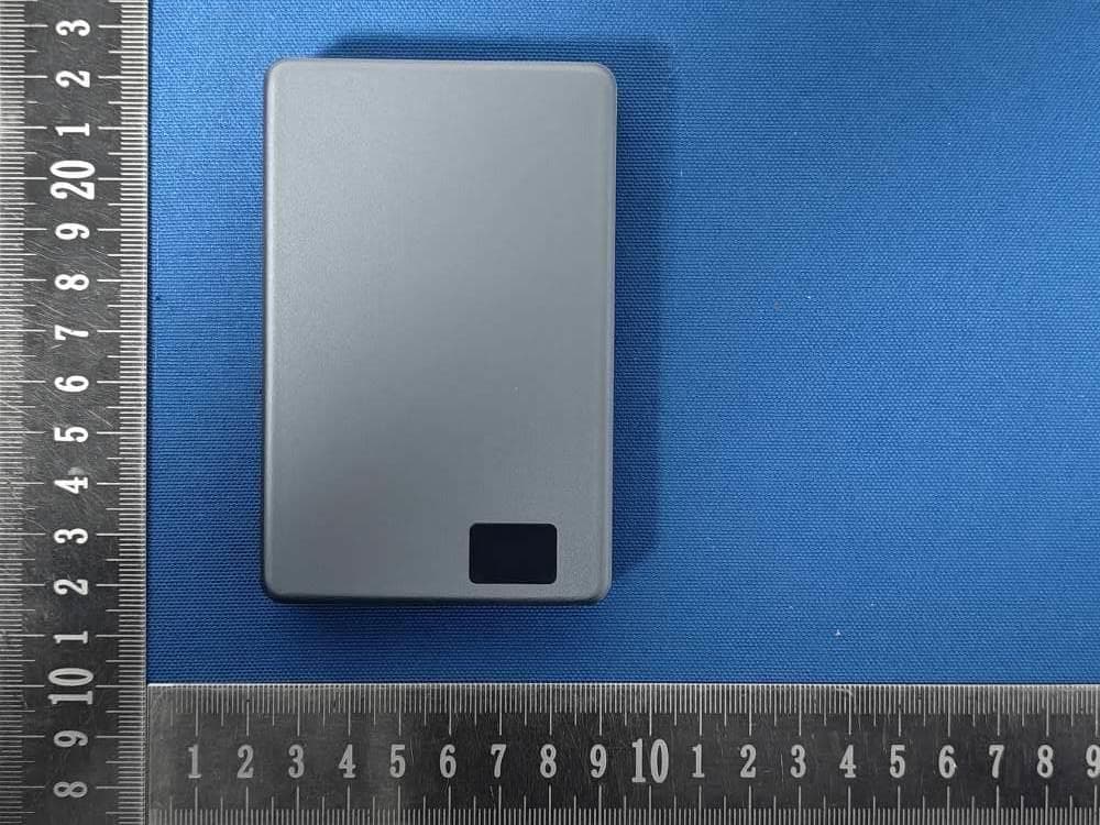
2A9Q9-M2319Q
Jun 05, 202610000mAh Wireless Power Bank
Equipment Class
DCD - Part 15 Low Power Transmitter Below 1705 kHz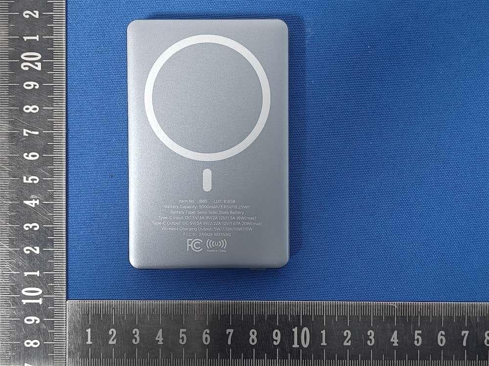
2A9Q9-M2359Q
Jun 05, 20265000mAh Wireless Power Bank
Equipment Class
DCD - Part 15 Low Power Transmitter Below 1705 kHz
2A9Q9-EPB-SL26
Mar 18, 2026Slimline 5000mAh 20W PD Aluminum Power Bank
Equipment Class
DCD - Part 15 Low Power Transmitter Below 1705 kHz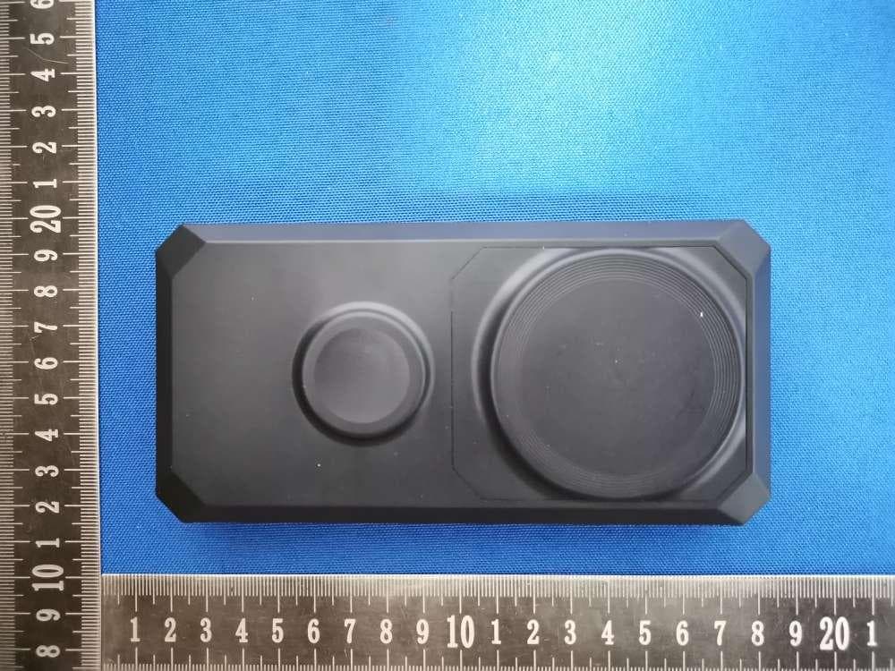
2A9Q9-EPB-AR26
Mar 16, 2026Array 15000mAh 20W Magnetic Wireless Power Bank
Equipment Class
DCD - Part 15 Low Power Transmitter Below 1705 kHz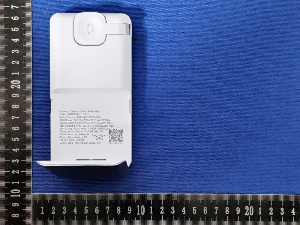
2A9Q9-EPB-DP26
Mar 05, 2026Diplomat 10000mAh 20W PD Power Bank
Equipment Class
DCD - Part 15 Low Power Transmitter Below 1705 kHz