2AA5WRGA100LWireless N ADSL2+ Modem Router
NEC Platforms, Ltd.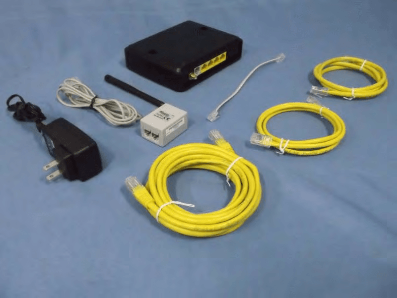
Click to zoom
Application Details
- Equipment Class
- DTS - Digital Transmission System
- Date of Grant
- Mar 11, 2014
- Application Purpose
- Original Equipment
- Date of Application
- Feb 26, 2014
- Equipment Note
- Wireless N ADSL2+ Modem Router
- Frequency Range
- 2412.00000000 - 2462.00000000
- Company
- NEC Platforms, Ltd.
- Country
- Japan
Documents & Files
Document Text
Text extracted from the exhibit documents filed with the FCC. Open a document above to read the original.
Users Manual
RG-A100L Instruction Manual 2 Contents Contents ......................................................................................... 2 Important Product Information ....................................................... 3 FCC Regulatory Statements .......................................................... 4 Safety Instructions ......................................................................... 6 Notice ........................................................................................... 13 1. Package Contents ................................................................... 16 2. Part Names and Functions ...................................................... 17 3. Installation Space .................................................................... 22 4. Network Setup ......................................................................... 23 5. Web Setting ............................................................................. 25 6. Products Specifications ........................................................... 26 Customer Information .................................................................. 28 Windows® and Windows Vista® are registered trademarks of Microsoft Corporation in the United States and other countries. Windows Vista® is an operating system. Copyright© NEC AccessTechnica, Ltd. 2013 3 Important Product Information Important safety information regarding radio frequency (RF) exposure and use when worn To ensure compliance at all times with the Radio Equipment and Telecommunications Terminal Equipment Directive 1999/5/EC* (R&TTE Directive) the equipment when in operation requires a minimum of 7cm separation from the body. Failure to observe these instructions could result in your RF exposure exceeding the compliance with Annex II of Council Recommendation 1999/519/EC. * The General Public RF exposure limits referenced in the R&TTE Directive are consistent with the guidelines of the International Commission on Non-Ionizing Radiation Protection (ICNIRP) published in 1998. ICNIRP is the formally recognized non-governmental organization in Non-Ionizing Radiation Protection for the World Health Organization (WHO), the International Labour Organization (ILO) and the European Union (EU). We, NEC AccessTechnica, Ltd. hereby, declare that the residential gateway model RG-A100L is in compliance with the essential requirements and other relevant provisions of Directive 1999/5/EC. A copy of the 1999/5/EC Declaration of Conformity can be perused in this Web address: http://www.necat.co.jp/en/ce/RG-A100L_DoC.pdf 4 FCC Regulatory Statements FCC part 68 This equipment complies with Part 68 of the FCC Rules. On the bottom of this equipment is a label that contains the FCC Registration Number and Ringer Equivalence Number (REN) for this equipment. You must provide this information to the telephone company upon request. The REN is useful to determine the quantity of devices you may connect to the telephone line and still have those entire devices ring when your number is called. In most, but not all areas, the sum of the REN of all devices connected to one line should not exceed five (5.0). To be certain of the number of devices you may connect to your line, as determined by the REN, you should contact your local telephone company to determine the maximum REN for your calling area. If the modem causes harm to the telephone network, the telephone company may discontinue your service temporarily. If possible, they will notify you in advance. But if advance notice isn't practical, you will be notified as soon as possible. You will be advised of your right to file a complaint with the FCC. The telephone company may make changes in its facilities, equipment, operations, or procedures that could affect the proper operation of your equipment. If they do, you will be notified in advance to give you an opportunity to maintain uninterrupted telephone service. If you experience trouble with this modem, please contact your dealer for repair/warranty information. The telephone company may ask you to disconnect this equipment from the network until the problem has been corrected or you are sure that the equipment is not malfunctioning. This equipment may not be used on coin service provided by the telephone company. Connection to party lines is subject to state tariffs. Installation: This device is equipped with a USOC RJ-11C connector. 5 FCC part 15 This equipment has been tested and found to comply with the limits for Class B digital device, pursuant to Part 15 of the FCC regulations. These limits are designed to provide reasonable protection against harmful interface in a residential installation. This equipment generates, uses and can radiate radio frequency energy and, if not installed and used in accordance with the instructions, may cause harmful interference to radio communications. However, there is no guarantee that interface will not occur in a particular installation. If this equipment does cause harmful interface to radio or television reception, which can be determined by turning the equipment off and on, the user is encouraged to try to correct the interface by one or more of the following measures: - Reorient or relocate the receiving antenna. - Increase the separation between the equipment and receiver. - Connect the equipment into an outlet on a circuit different from that to which the receiver is connected. - Consult the dealer or an experienced radio/TV technician for help. Caution: Any changes or modifications not expressly approved by the party responsible for compliance could void the user’s authority to operate this equipment. Note: This device complies with Part 15 of the FCC Rules. Operation is subject to the following two conditions: (1) This device may not cause harmful interface. (2) This device must accept any interface received, including interface that may cause undesired operation. 6 Safety Instructions Please read these Safety Instruction…
Text truncated - open the document above for the full version.
External Photos
Report No: 139322R-RFUSP42V01 Page: 189 of 196 Attachement EUT Photograph (1) EUT Photo (2) EUT Photo
ID Label/Location Info
FCC ID.: 2AA5WRGA100L FCC ID AND DoC Label
ID Label/Location Info
FCC ID.: 2AA5WRGA100L FCC ID AND DoC Label
Internal Photos
Report No: 139322R-RFUSP42V01 Page: 190 of 196 (3) EUT Photo (4) EUT Photo Report No: 139322R-RFUSP42V01 Page: 191 of 196 (5) EUT Photo (6) EUT Photo Report No: 139322R-RFUSP42V01 Page: 192 of 196 (7) EUT Photo (8) EUT Photo Report No: 139322R-RFUSP42V01 Page: 193 of 196 (9) EUT Photo (10) EUT Photo Report No: 139322R-RFUSP42V01 Page: 194 of 196 (11) EUT Photo (12) EUT Photo (MB) Report No: 139322R-RFUSP42V01 Page: 195 of 196 (13) EUT Photo (ANT) (14) EUT Photo Report No: 139322R-RFUSP42V01 Page: 196 of 196 (15) EUT Photo
RF Exposure Info
Report No. 139322R-RF-US-Exp Page: 1 of 5 RF Exposure Evaluation Declaration Product Name :Wireless N ADSL2+ Modem Router Model No. :RG-A100L FCC ID. :2AA5WRGA100L Applicant : NEC AccessTechnica, Ltd. Address : 800 Shimomata, Kakegawa, Shizuoka 436-8501 Japan Date of Receipt : 2013/09/11 Date of Declaration : 2013/11/13 Report No. : 139322R-RF-US-Exp Report Version : V1.0 The declaration results relate only to the samples calculated. The declaration shall not be reproduced except in full without the written approval of QuieTek Corporation. Report No. 139322R-RF-US-Exp Page: 2 of 5 1. RF Exposure Evaluation 1.1. Limits According to FCC 1.1310: The criteria listed in the following table shall be used to evaluate the environment impact of human exposure to radio frequency (RF) radiation as specified in 1.1307(b) LIMITS FOR MAXIMUM PERMISSIBLE EXPOSURE (MPE) Frequency Range (MHz) Electric Field Strength (V/m) Magnetic Field Strength (A/m) Power Density (mW/cm 2 ) Average Time (Minutes) (A) Limits for Occupational/ Control Exposures 300-1500 -- -- F/300 6 1500-100,000 -- -- 5 6 (B) Limits for General Population/ Uncontrolled Exposures 300-1500 -- -- F/1500 6 1500-100,000 -- -- 1 30 F= Frequency in MHz Friis Formula Friis transmission formula: Pd = (Pout*G)/(4*pi*r 2 ) Where Pd = power density in mW/cm 2 Pout = output power to antenna in mW G = gain of antenna in linear scale Pi = 3.1416 R = distance between observation point and center of the radiator in cm Pd id the limit of MPE, 1 mW/cm 2 . If we know the maximum gain of the antenna and the total power input to the antenna, through the calculation, we will know the distance r where the MPE limit is reached. 1.2. Test Procedure Software provided by client enabled the EUT to transmit and receive data at lowest, middle and highest channel individually. The temperature and related humidity: 18°Cand 78% RH. Report No. 139322R-RF-US-Exp Page: 3 of 5 1.3. Test Result of RF Exposure Evaluation Product Wireless N ADSL2+ Modem Router Test Mode Transmit Test Condition RF Exposure Evaluation Antenna Gain Antenna Gain: The maximum Gain measured in fully anechoic chamber is 2dBi or 1.58 in linear scale. Output Power into Antenna & RF Exposure Evaluation Distance: IEEE 802.11b WLAN Function Channel Channel Frequency (MHz) Output Power to Antenna (mW) Power Density at R = 20 cm (mW/cm 2 ) 1 2412 31.4051 0.00987 6 2437 22.8034 0.00717 11 2462 18.7068 0.00588 IEEE 802.11g WLAN Function Channel Channel Frequency (MHz) Output Power to Antenna (mW) Power Density at R = 20 cm (mW/cm 2 ) 1 2412 45.2898 0.01424 6 2437 34.0408 0.01070 11 2462 28.2488 0.00888 The power density Pd (4th column) at a distance of 20 cm calculated from the Friis transmission formula is far below the limit of 1 mW/cm 2 . Report No. 139322R-RF-US-Exp Page: 4 of 5 Product Wireless N ADSL2+ Modem Router Test Mode Transmit Test Condition RF Exposure Evaluation Antenna Gain Antenna Gain: The maximum Gain measured in fully anechoic chamber is 2dBi or 1.58 in linear scale. Output Power into Antenna & RF Exposure Evaluation Distance: IEEE 802.11n (20MHz) ANT 0 WLAN Function Channel Channel Frequency (MHz) Output Power to Antenna (mW) Power Density at R = 20 cm (mW/cm 2 ) 1 2412 35.4813 0.01115 6 2437 26.8534 0.00844 11 2462 21.7771 0.00685 The power density Pd (4th column) at a distance of 20 cm calculated from the Friis transmission formula is far below the limit of 1 mW/cm 2 . Report No. 139322R-RF-US-Exp Page: 5 of 5 Product Wireless N ADSL2+ Modem Router Test Mode Transmit Test Condition RF Exposure Evaluation Antenna Gain Antenna Gain: The maximum Gain measured in fully anechoic chamber is 2dBi or 1.58 in linear scale. Output Power into Antenna & RF Exposure Evaluation Distance: IEEE 802.11n (40MHz) ANT 0 WLAN Function Channel Channel Frequency (MHz) Output Power to Antenna (mW) Power Density at R = 20 cm (mW/cm 2 ) 3 2422 12.4738 0.00392 6 2437 10.4713 0.00329 9 2452 9.0991 0.00286 The power density Pd (4th column) at a distance of 20 cm calculated from the Friis transmission formula is far below the limit of 1 mW/cm 2 .
Test Report
Report No: 139322R-RFUSP42V01 Page: 1 of 196 FCC Test Report Product Name :Wireless N ADSL2+ Modem Router Model No. :RG-A100L FCC ID. :2AA5WRGA100L Applicant : NEC AccessTechnica, Ltd. Address : 800 Shimomata, Kakegawa, Shizuoka 436-8501 Japan Date of Receipt:2013/09/11 Issued Date :2013/11/13 Report No. :139322R-RFUSP42V01 Report Version :V1.0 The test results relate only to the samples tested. The test report shall not be reproduced except in full without the written approval of QuieTek Corporation. Report No: 139322R-RFUSP42V01 Page: 2 of 196 Test Report Certification Issued Date : 2013/11/13 Report No. : 139322R-RFUSP42V01 Product Name : Wireless N ADSL2+ Modem Router Applicant : NEC AccessTechnica, Ltd. Address : 800 Shimomata, Kakegawa, Shizuoka 436-8501 Japan Model No. : RG-A100L FCC ID. : 2AA5WRGA100L EUT Test Voltage : AC 100-240V, 50/60Hz Trade Name : NEC Applicable Standard : FCC CFR Title 47 Part 15 Subpart C Section 15.247: 2012 ANSI C63.4: 2009 Test Result : Complied The test results relate only to the samples tested. The test report shall not be reproduced except in full without the written approval of QuieTek Corporation. Documented By : (Demi Chang / Engineering Adm. Specialist) Reviewed By : ( JuBo Shen / Engineer ) Approved By : ( Roy Wang / Director ) Report No: 139322R-RFUSP42V01 Page: 3 of 196 Laboratory Information We, QuieTek Corporation, are an independent RF consultancy that was established the whole facility in our laboratories. The test facility has been accredited/accepted (audited or listed) by the following related bodies in compliance with ISO 17025 specified testing scopes: The related certificate for our laboratories about the test site and management system can be downloaded from QuieTek Corporation’s Web Site:http://www.quietek.com/tw/ctg/cts/accreditations.htm The address and introduction of QuieTek Corporation’s laboratories can be founded in our Web site : http://www.quietek.com/ If you have any comments, Please don’t hesitate to contact us. Our contact information is as below: HsinChu Testing Laboratory: No.75-2, 3rd Lin, Wangye Keng, Yonghxing Tsuen, Qionglin Shiang, Hsinchu County 307, Taiwan, R.O.C. TEL:+886-3-592-8858 / FAX:+886-3-592-8859 E-Mail : [email protected] LinKou Testing Laboratory: No.5-22, Ruishukeng, Linkou Dist., New Taipei City 24451, Taiwan, R.O.C. TEL : 886-2-8601-3788 / FAX : 886-2-8601-3789 E-Mail : [email protected] Taiwan R.O.C. : TAF, Accreditation Number: 1313 NCC, Certificate No : NCC-RCB-07 USA : FCC, Registration Number: 365520 Canada : IC, Submission No: 150981 Report No: 139322R-RFUSP42V01 Page: 4 of 196 TABLE OF CONTENTS Description Page 1. General Information.............................................................................................................. 6 1.1. EUT Description ............................................................................................................. 6 1.2. Operational Description ................................................................................................ 10 1.3. Test Mode ..................................................................................................................... 11 1.4. Tested System Details .................................................................................................. 12 1.5. Configuration of tested System .................................................................................... 13 1.6. EUT Exercise Software ................................................................................................ 13 1.7. Test Facility...................................................................................................................14 2. Conducted Emission .......................................................................................................... 15 2.1. Test Equipment............................................................................................................. 15 2.2. Test Setup .................................................................................................................... 15 2.3. Limits ............................................................................................................................ 16 2.4. Test Procedure ............................................................................................................. 16 2.5. Test Specification.......................................................................................................... 16 2.6. Uncertainty ................................................................................................................... 16 2.7. Test Result....................................................................................................................17 2.8. Test Photo .................................................................................................................... 19 3. Peak Power Output ............................................................................................................ 20 3.1. Test Equipment............................................................................................................. 20 3.2. Test Setup .................................................................................................................... 20 3.3. Test procedures ............................................................................................................ 20 3.4. Limits ............................................................................................................................ 20 3.5. Test Specification.......................................................................................................... 20 3.6. Uncertainty ................................................................................................................... 20 3.7. Test Result....................................................................................................................21…
Text truncated - open the document above for the full version.
Test Setup Photos
Report No: 139322R-RFUSP42V01 Page: 19 of 196 2.8. Test Photo Test Mode : Mode 1: Transmit Description: Front View of Conducted Emission Test Setup Test Mode : Mode 1: Transmit Description: Back View of Conducted Emission Test Setup Report No: 139322R-RFUSP42V01 Page: 71 of 196 4.8. Test Photo Test Mode : Mode 1: Transmit Description: Front View of Radiated Emission Test Setup (Bi-Log) Test Mode : Mode 1: Transmit Description: Back View of Radiated Emission Test Setup (Bi-Log) Report No: 139322R-RFUSP42V01 Page: 72 of 196 Test Mode : Mode 1: Transmit Description: Front View of Radiated Emission Test Setup (Horn) Test Mode : Mode 1: Transmit Description: Back View of Radiated Emission Test Setup (Horn)
Contact Information
Applicant
Mitsuru Ohya(Senior manager)
Technical Contact
Non-Technical Contact
QuieTek CorporationNeil Yeh
[email protected]886-3-592-8858
Test Firm
QuieTek CorporationWarren Lin
Technical Specifications
| # | Rule Parts | Frequency Range | Power Output |
|---|---|---|---|
| 1 | 15C | 2.41 GHz - 2.46 GHz | 45.00 mW |
Other Applications from NEC Platforms, Ltd.
2AA5WKMP7R2BC
Feb 02, 2021Aterm MR10LN
Equipment Class
PCB - PCS Licensed Transmitter
2AA5WPAMR04LN
Apr 22, 2015AtermMR04LN
Equipment Class
DTS - Digital Transmission System
2AA5WRGG201L
Mar 16, 2014Residential Gateway
Equipment Class
DTS - Digital Transmission System
2AA5WPAMR03LN
Jan 19, 2014PA MR03LN
Equipment Class
DTS - Digital Transmission System