2AA8W-OCAMS1IP Cam
AHOKU ELECTRONIC COMPANY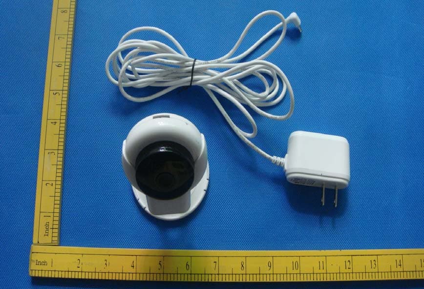
Click to zoom
Application Details
- Equipment Class
- DTS - Digital Transmission System
- Date of Grant
- Dec 16, 2015
- Application Purpose
- Original Equipment
- Date of Application
- Dec 13, 2015
- Equipment Note
- IP Cam
- Frequency Range
- 2412.00000000 - 2462.00000000
- Company
- AHOKU ELECTRONIC COMPANY
- Country
- Taiwan
Documents & Files
Document Text
Text extracted from the exhibit documents filed with the FCC. Open a document above to read the original.
Users Manual
1、Install Anycam 1.1 、 Download and install the P2P application”Anycam” 。 1.2 、 Search the Application ”Anycam” on application store , and download it on your phone (Android users can get it from “Android Market” , or find and install the APP from the CD attached; iOS users can download on App Store )。 1.3 、 Install the the application on your mobile phone and then run it. 2、Add cameras 2.1、Add new device 2.1.1、The app can support to add :Camera、Aircraft、DooBell(Only support camera now).First ,the camera through the power supply (Do not connect the network cable), hear the "bit" twice after entering the SmartLink mode. Please make your phone connect to the WIFI, run "Anycam", register and login into the software page. Click the Add button at the main page, select Add Camera. 2.1.2 、 Click “add new device” and enter the SSID and password of wifi , Then, Click “config” button , the camera will connect the wifi by SmartLink mode. After that , the P2P of the camera will be displayed on screen .Finally, Click “ + ” button to add camera. 2.1.2 、 Enter user name and password of the camera (user name, password, factory default: admin), and named the camera . Click Save after completing the above steps, the new camera is added success. Return to the main page, just add a successful camera will be displayed in the device list, click the arrow next to enter the control page of the camera. In the monitoring page, we can screenshots, video, voice intercom, view the video, alarm recording, and other operations to control the camera rotation. 2.2、Add online device If you want to add the device online, you can add the camera by adding existing device. There are three ways to add GID: Search manually input, two-dimensional code scanning, Search in the LAN. The factory default of user name and password is: admin. Click Save after adding the top right. The camera will be displayed in the device list after successfully added. 3、Camera settings 3.1 、 In Surveillance camera page, click the button of setting , we can upgrade the firmware of camera, alarm settings, and advanced settings. 3.2 、 In the Advanced settings we can set the camera's advanced features: reset the password, motion detection (arming switch, linkage SD card capture, video), scheduled recording, time settings, reboot the device. 3.3 、 In the main page, we can delete the added cameras and feature set. This device complies with Part 15 of the FCC Rules. Operation is subject to the following two conditions: (1) this device may not cause harmful interference, and (2) this device must accept any interference received, including interference that may cause undesired operation. (2) Changes or modifications not expressly approved by the party responsible for compliance could void the user's authority to operate the equipment ̃ ̃ (3) NOTE: This equipment has been tested and found to comply with the limits for a Class B digital device, pursuant to Part 15 of the FCC Rules. These limits are designed to provide reasonable protection against harmful interference in a residential installation. This equipment generates, uses instructions, may cause harmful interference to radio communications. However, there is no guarantee that interference will not occur in a particular installation. If this equipment does cause harmful interference to radio or television reception, which can be determined by turning the equipment off and on, the user is encouraged to try to correct the interference by one or more of the following measures: -- Reorient or relocate the receiving antenna. -- Increase the separation between the equipment and receiver. -- Connect the equipment into an outlet on a circuit different from that to which the receiver is connected. -- Consult the dealer or an experienced radio/TV technician for help.
Cover Letter(s)
November 27, 2015 Equipment Autorisation Division Federal Communications Commission 7435 Oakland Mills Road Columbia, MD 21046 FCC ID: 2AA8W-OCAMS1 _ Product Name: IP cam Request for Confidentiality Pursuant to Sections 0.457 and 0.459 of the commissions rules, we hereby request that the following documents be held confidential: • Schematics Long-term confidential • Block diagram Long-term confidential • Operation description Long-term confidential These materials contain trade secrets and proprietary information and are not customarily released to the public. The public disclosure of this information might be harmful to the company and provide unjustified benefits to our competitors. Dated this November 27, 2015 Agency agreement expiration date: Usually Give 8 - 12 Months By: Leo cheng Signature Printed Title: Project Manager On behalf of : (Company Name) Ahoku Electronic Company Telephone: +886-2799-1199
ID Label/Location Info
25mm 50mm 10mm FCC ID: 2AA8W-OCAMS1
ID Label/Location Info
Label location
Internal Photos
Antenna
RF Exposure Info
RF Exposure evaluation According to 447498 D01 General RF Exposure Guidance v05 The 1-g and 10-g SAR test exclusion thresholds for 100 MHz to 6 GHz at test separation distances ≤ 50 mm are determined by: [(max. power of channel, including tune-up tolerance, mW)/(min. test separation distance, mm)] ·[√ f(GHz)] ≤ 3.0 for 1-g SAR and ≤ 7.5 for 10-g extremity SAR, where f(GHz) is the RF channel transmit frequency in GHz Power and distance are rounded to the nearest mW and mm before calculation The result is rounded to one decimal place for comparison Worse case is as below: [2437 MHz 9.41 dBm(8.73 mW)output power] (8.73 mW /5mm) ·[√2.4 37(GHz)]= 2.74 <3.0 for 1-g SAR Then SAR evaluation is not required
Test Report
FCC RADIO TEST REPORT FCC ID: 2AA8W-OCAMS1 Applicant : Ahoku Electronic Company Address : 5F, No.88, Sec.1 Nei-Hu Road, Taipei, Taiwan, R.O.C. Equipment under Test (EUT): Name : IP cam Model : OCamS1, OCamS2, OCamS3, OcamS4, OcamS5 Trademark : OCam Standards : FCC PART 15, SUBPART C : 2014 (Section 15.247) Report No. : CTB151113002Q Date of Test : November 17-25, 2015 Date of Issue : November 26, 2015 Test Result : PASS * In the configuration tested, the EUT complied with the standards specified above Authorized Signature (Simon Lee) General Manager The manufacture should ensure that all the products in series production are in conformity with the product sample detailed in this report. If the product in this report is used in any configuration other than that detailed in the report, the manufacturer must ensure the new system complies with all relevant standards. Any mention of Shenzhen CTB Testing Technology Co., Ltd. Or test done by Shenzhen CTB Testing Technology Co., Ltd. Approvals in connection with, distribution or use of the product described in this report must be approved by Shenzhen CTB Testing Technology Co., Ltd Approvals in writing. Page 2 of 54 TABLE OF CONTENT Description Page 1 General Information ---------------------------------------------------------------------------------------- 4 1.1 Description of Device (EUT) --------------------------------------------------------------------- 4 1.2 Description of Test Facility ----------------------------------------------------------------------- 4 2 EMC Equipment List --------------------------------------------------------------------------------------- 4 3 Test Procedure ----------------------------------------------------------------------------------------------- 6 4 Summary of Measurement ----------------------------------------------------------------------------- 7 4.1 Summary of test result ---------------------------------------------------------------------------- 7 4.2 Test connection ------------------------------------------------------------------------------------- 7 4.3 Assistant equipment used for test ---------------------------------------------------------------- 8 4.4 Test mode ------------------------------------------------------------------------------------------- 8 4.5 Channel list ----------------------------------------------------------------------------------------- 9 4.6 Test Conditions ------------------------------------------------------------------------------------- 9 4.7 Measurement Uncertainty (95% confidence levels, k=2)------------------------------------- 9 5 Spurious Emission ---------------------------------------------------------------------------------------- 9 5.1 Radiation Emission ------------------------------------------------------------------------------ 10 5.1.1 Radiation Emission Limits(15.209) ----------------------------------------------------------- 10 5.1.2 Test Setup ----------------------------------------------------------------------------------------- 10 5.1.3 Test Procedure ------------------------------------------------------------------------------------ 12 5.1.4 Test Equipment Setting For emission test Result -------------------------------------------- 12 5.1.5 Test Condition ------------------------------------------------------------------------------------ 12 5.1.6 Test Result ---------------------------------------------------------------------------------------- 12 6 POWER LINE CONDUCTED EMISSION ------------------------------------------------------ 18 6.1 Conducted Emission Limits(15.207) ---------------------------------------------------------- 18 6.2 Test Setup ----------------------------------------------------------------------------------------- 18 6.3 Test Procedure ------------------------------------------------------------------------------------ 18 6.4 Test Results --------------------------------------------------------------------------------------- 18 7 Conducted Maximum Output Power--------------------------------------------------------------- 21 7.1 Test limit ------------------------------------------------------------------------------------------ 21 7.2 Test Procedure ------------------------------------------------------------------------------------ 21 7.3 Test Setup ----------------------------------------------------------------------------------------- 21 7.4 Test Results --------------------------------------------------------------------------------------- 21 8 PEAK POWER SPECTRAL DENSITY ---------------------------------------------------------- 23 8.1 Test limit ------------------------------------------------------------------------------------------ 23 8.1.1 Please refer section15.247. -------------------------------------------------------------------- 23 8.2 Method of measurement ------------------------------------------------------------------------ 23 8.3 Test Setup ----------------------------------------------------------------------------------------- 23 8.4 Test Results --------------------------------------------------------------------------------------- 24 9 Bandwidth ----------------------------------------------------------------------------------------------- 27 9.1 Test limit ------------------------------------------------------------------------------------------ 27 9.2 Method of measurement ------------------------------------------------------------------------ 27 9.3 Test Setup ----------------------------------------------------------------------------------------- 27 9.4 Test Results --------------------------------------------------------------------------------------- 27 10 Band Edge Check -------------------------------------------------------------------------------------- 31 10.1 Test limit ------------------------------------------------------------------------------------------ 31 10.2 Test Procedure ------------------------------------------------------------------------------------ 31 …
Text truncated - open the document above for the full version.
Test Setup Photos
Radiated emission
Contact Information
Applicant
Leo cheng(Project Manager)
Test Firm
Shenzhen CTB Testing Technology Co., Ltd.Simon Lee
[email protected]13662574496
Technical Specifications
| # | Rule Parts | Frequency Range | Power Output |
|---|---|---|---|
| 1 | 15C | 2.41 GHz - 2.46 GHz | 8.73 mW |
Other Applications from AHOKU ELECTRONIC COMPANY
2AA8WOCAM-M1
Jan 27, 2015WiFi Vedio Camera
Equipment Class
DTS - Digital Transmission System
2AA8WEEC230WIFI
Nov 08, 2013WiFi Travel Router
Equipment Class
DTS - Digital Transmission System