2AABT-CW001Low voltage quick set tree with remote controller
Polygroup Limited(Macao Commercial Offshore)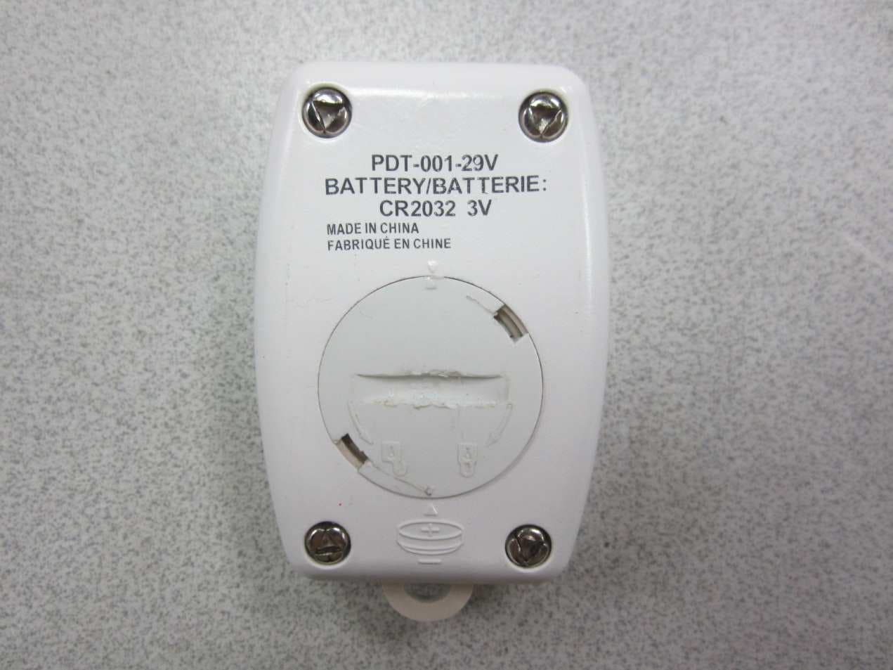
Click to zoom
Application Details
- Equipment Class
- DSC - Part 15 Security/Remote Control Transmitter
- Date of Grant
- Jun 20, 2013
- Application Purpose
- Original Equipment
- Date of Application
- Jun 19, 2013
- Equipment Note
- Low voltage quick set tree with remote controller
- Frequency Range
- 433.92000000 - 433.92000000
- Country
- China
Documents & Files
Document Text
Text extracted from the exhibit documents filed with the FCC. Open a document above to read the original.
Users Manual
1. Before you start to assemble your tree, choose an appropriate location near a wall outlet. 2. Assemble the tree stand and place on a level surface. (See Fig. A) Congratulations on purchasing your new tree from Polytree®! This tree assmebles with Quick Set® technology -Set up and light up your tree in less than 10 minutes! Carefully follow the instructions below on how to quickly and easily set up your new tree. TREE ASSEMBLY INSTRUCTIONS Top view Side view Fig. C ASSEMBL Y INSTR UCTIONS MADE IN CHINA 3. Each tree section is numbered with a tag. Please identify all sections before assembling. 4. Assemble the tree from the bottom to the top. Start with the bottom section and remove protective cap before inserting into the assembled stand. Make sure the pole is firmly inserted and secured into the stand. 5. Please remove protective cap from middle section(s) and continue inserting into the bottom section until the tree top is inserted. 6. Allow branches to fall into place or gently pull up and out. When adjusting branches, be sure that all wires are free of branch hinges. 7. Insert green label extension cord plug into the wall outlet (see Fig. B ), your entire tree should now be lit. If some bulbs do not light or flicker, search for any loose plugs and/or broken, loose or missing bulbs. Connect the plugs or replace the bad bulbs promptly in order to maintain the performance and life expectancy of your pre-lit tree. 8. Begin to shape the branches and tips working from the bottom to the top. Start with tips farthest from the pole and fan out one to the right, one to the left and one at the center of the main stem. (See Fig. C) 9. After shaping the entire tree following the previous step, slightly upsweep all branch tips for a uniform look. Shift branches to fill any gaps. Your Christmas tree is now complete and ready to be decorated. MODEL #: XXXXXX *Electrical Rating For The Tree (For Indoor Use Only) Input:100-240VAC, 50/60Hz, 0.5A Max. Output: 29V DC 0.5A Fig. B - Tree and Light Assembly Power Cord to Wall Outlet On/Off Switch Section 1 Section 2 Section 3 50S 100S 100S 50S 100S 100S 100S Control box 100S 100S Do Not Tamper Internal Parts Remove the protective cap Do Not Tamper Internal Parts Remove the protective cap Fig. A - Tree Stand Assembly Slide the legs upwards into slots at the base of the trunk and tap lightly with hammer until firmly fixed. On/Off Switch Fig.D Light Controller Selector Button Remote Controller 1. Unplug extension cord from the wall outlet first and then remove all ornaments and decorations. 2. Disassemble the tree from the top to the bottom. Start with the tree top and gently lift straight up to remove from section below and fold all branches toward the pole. 3. Continue by gently lifting straight up each section(s) from the section below and fold all branches toward the pole until the bottom section is removed from the tree stand. Cover the protective cap on the poles to avoid damaging the internal parts.(See Fig.D) 4. Carefully place all tree sections into shipping box and tape it shut. 5. When not in use, please store your tree in a cool, dry place away from sunlight. Exposing your tree to excessive heat or humidity may damage your tree. STORAGE INSTRUCTIONS TROUBLE SHOOTING TIPS Each tree includes hinge pins/washers, and for pre-lit trees spare bulbs and fuses are also included. If extra parts are needed, please contact our customer service center. SPARE PARTS Press the selector button on the “Dual Color Light Controller” or “Remote Controller” to select among: (1) CLEAR AND MULTI-COLOR ALTERNATING; (2) CLEAR LIGHTS; (3) MULTI LIGHTS and (4) TURN OFF BOTH LIGHTS. Note: The lights will be automatically reset to “CLEAR AND MULTI-COLOR ALTERNATING” every time the product is powered up. For the remote controller, replace only with CR2032 battery. See bottom of the remote controller for replacement instruction. WARNING 1. Use only power adaptor supplied with this product, using a different adaptor will damage the lights . and cause fire, electrical shock hazards. 2. FOR INDOOR USE ONLY. HOW TO USE THE DUAL COLOR LIGHT CONTROLLER AND REMOTE CONTROL: ASSEMBLY INSTRUCTIONS MADE IN CHINA Fig.E CUSTOMER SERVICE FOR CHRISTMAS TREES For any questions, assistance, or missing parts, please contact us at 1-888-919-0070 or visit our website at www.polygroup.com. One of our customer service representatives will be happy to assist you. TREE ID# IS LOCATED ON END PANEL OF BOX. TREE ID# IS REQUIRED WHEN REQUESTING REPLACEMENT PARTS. Customer Name: Address:(No P.O. Boxes) City & State: Zip Code: Day Phone: Date Purchased: Tree ID#: Tree UPC#: Store Purchased: Specify Problem: For Pre-lit Trees, If The Tree Does Not Illuminate 1. Please check to make sure that all plugs are properly connected and power cord is plugged into the wall outlet. 2. Turning the poles gently to make sure pole to pole are connected into place. 3. Please check for blown fuses at the light string plugs and power cord plug. Replace as needed. Note: Please make sure to use appropriate replacement fuses as indicated on the light string plug and power cord plug. 4. Please check for loose, broken or missing light bulbs and replace as needed. Loose Hinge Pin 1. Extra hinge pins are included for repairing the hinges. Place the branch into the slot of the bracket. 2. Insert a new hinge pin through the hole and secure using the retainer washer. (See Fig. E) IMPORTANT SAFETY INSTRUCTIONS USE AND CARE INSTRUCTIONS ASSEMBLY INSTRUCTIONS MADE IN CHINA When using electrical products, basic precautions should always be followed, including the following: a. READ AND FOLLOW ALL SAFETY INSTRUCTIONS. b. Do not use seasonal products outdoors unless marked suitable for indoor and outdoor use. When products are used in outdoor applications, connect the product to a Ground Fault Circuit Interrupting (GFCI) outlet. If one is not provided, contact a qualified electrician for proper installation. c. This seasonal product is not i…
Text truncated - open the document above for the full version.
Block Diagram
ASK
Operational Description
Technical Description 描述 功能 零件 天线 发射无线信号 天线 滤波器 过滤主频 C1,C2,L1 振荡器 产生433.92MHZ频率 IC1,Y1,C6,C7 编码IC 产生编码信号 IC2 Description Function Component Antenna Transmit radio signals Antenna Filter Filter frequency C1,C2,L1 Oscillator Generate 433.92MHZ carrier IC1,Y1,C6,C7 Encode IC Generate code signal IC2
Schematics
1234 A B C D 4 321 D C B A Title NumberRevisionSize A4 Date:10-Jun-2013Sheet of File:E:\快盘\2013LS\RF FLASH\RF Flash(冲突2013-04-10 00-12-33).ddbDrawn By: VDD 1 PB5 2 PB4 3 PB3 4 PB2 5 PB1 6 PB0 7 VSS 8 IC2 PAOUT 1 VSS 2 VDD 3 XTLOUT 4 XTLIN 5 ASK 6 IC1 F113 C6 18P C7 18P Y1 13.560MHZ R1 10K VCC L2 82nH C2 10pF L1 47nH E1 ANTENNA C5 100P C4 105 R2 3.3K D1 LED VCC S1 SW-PB C3 105 BT1 CR2032 VCC TX DATA Q1 8550 R3 1.0k R4 1.0k C1 5.6P 433.92MHZ PDF 文件使用 "pdfFactory Pro" 试用版本创建 www.fineprint.com.cn
Test Report
Report No.: 130422074GZU-001 Issued: 31 May 2013 Page 2 of 14 FCC ID: 2AABT-CW001 Table of Contents TEST REPORT ........................................................................................................................................................... 1 1 General Description .................................................................................................................................... 3 1.1 Product Description ...................................................................................................................................... 3 1.2 Related Submittal(s) Grants .......................................................................................................................... 3 1.3 Test Methodology ......................................................................................................................................... 3 1.4 Test Facility .................................................................................................................................................. 3 2 System Test Configuration ......................................................................................................................... 4 2.1 Justification ................................................................................................................................................... 4 2.2 EUT Exercising Software ............................................................................................................................. 4 2.3 Special Accessories ....................................................................................................................................... 4 2.4 Equipment Modification ............................................................................................................................... 4 2.5 Measurement Uncertainty ............................................................................................................................. 4 2.6 Support Equipment List and Description ...................................................................................................... 4 3 Radiated Emission Results ......................................................................................................................... 5 3.1 Field Strength Calculation ............................................................................................................................ 5 3.2 Radiated and Spurious Emission Data .......................................................................................................... 6 4 Bandwidth and Timing ............................................................................................................................... 9 4.1 Bandwidth Plot ............................................................................................................................................. 9 4.2 Timing Plot ................................................................................................................................................. 10 4.3 Calculation of Average Factor .................................................................................................................... 10 4.4 Emissions Test Procedures.......................................................................................................................... 13 4.5 Emissions Test Procedures (cont'd) ............................................................................................................ 13 5 Equipment list ........................................................................................................................................... 14 Report No.: 130422074GZU-001 Issued: 31 May 2013 Page 3 of 14 FCC ID: 2AABT-CW001 1 General Description 1.1 Product Description The equipment under test (EUT) is a controller for Low voltage quick set tree at 433.92 MHz. The EUT is powered by 3V DC. During normal use, it sends the signal to control the on/off and speed/colour change of LED light on the Christmas tree by manual. Antenna Type: PCB antenna. 1.2 Related Submittal(s) Grants The FCC ID of corresponding receiver tree for this transmitter is 2AABT-CW002. 1.3 Test Methodology Radiated emission measurements were performed according to the procedures in ANSI C63.10 (2009). Radiated Emission measurement was performed in a Semi-anechoic chamber. Preliminary scans were performed in the Semi-anechoic chamber only to determine worst case modes. For each scan, the procedure for maximizing emissions in clause 6.5 & 6.6 of ANSI C63.10 (2009) were followed. All Radiated tests were performed at an antenna to EUT distance of 3 meters unless stated otherwise. 1.4 Test Facility All of the tests are performed at: Keyway Technology Co.,Ltd. located at Baishun Industrial Zone, Zhangmotou Town, Dongguan, Guangdong, China 523638. This test facility and site measurement data have been fully placed on file with the FCC, test firm registration number is 370994. Report No.: 130422074GZU-001 Issued: 31 May 2013 Page 4 of 14 FCC ID: 2AABT-CW001 2 System Test Configuration 2.1 Justification The equipment under test (EUT) was configured for testing in a typical fashion (as a customer would normally use it), and in the confines as outlined in ANSI C63.10 (2009). The EUT was operated standalone and placed in the center of the turntable, which enabled the engineer to maximize emissions through its placement in the three orthogonal axes. For maximizing emission at and above 30 MHz, the EUT was rotated through 360°, the antenna height was varied from 1 meter to 4 meters above the ground plane, and the antenna polarization was changed. This step by step procedure for maximizing emissions led to the data of clause 3.3 in the report. 2.2 EUT Exercising Software There was no special software to exercise the device. 2.3 Special Accessories There are no special accessories necessary for compliance of this pro…
Text truncated - open the document above for the full version.
Contact Information
Applicant
Nathan Ke
Technical Contact
Intertek Testing Services Shenzhen Ltd.Helen Ma
[email protected]86-20-82139664
Block E, No.7-2 Guang Dong Software Science Park, · Guangzhou · China
Non-Technical Contact
Intertek Testing Services Shenzhen Ltd.Helen Ma
[email protected]86-20-82139664
Test Firm
Keyway Technology Co., LtdJade Yang
Technical Specifications
| # | Rule Parts | Frequency Range | Power Output |
|---|---|---|---|
| 1 | 15.231 | 433.92 MHz - 433.92 MHz | - |
Other Applications from Polygroup Limited(Macao Commercial Offshore)
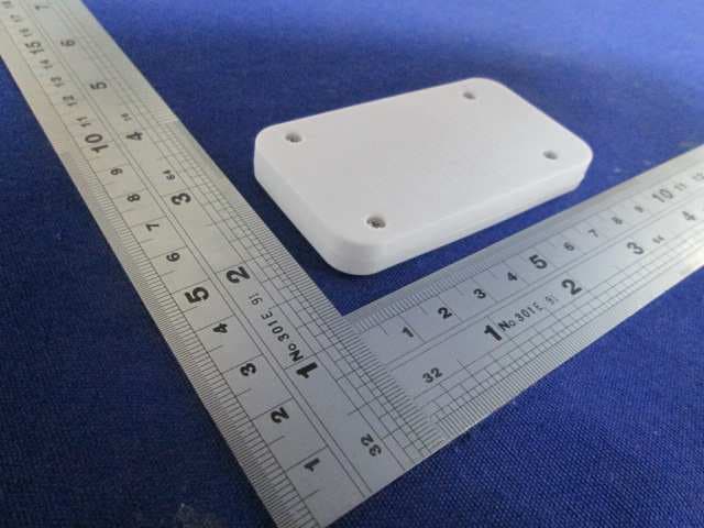
2AABT-LUMALIGHT-C
Nov 22, 2015Luma Light Pool
Equipment Class
DSC - Part 15 Security/Remote Control Transmitter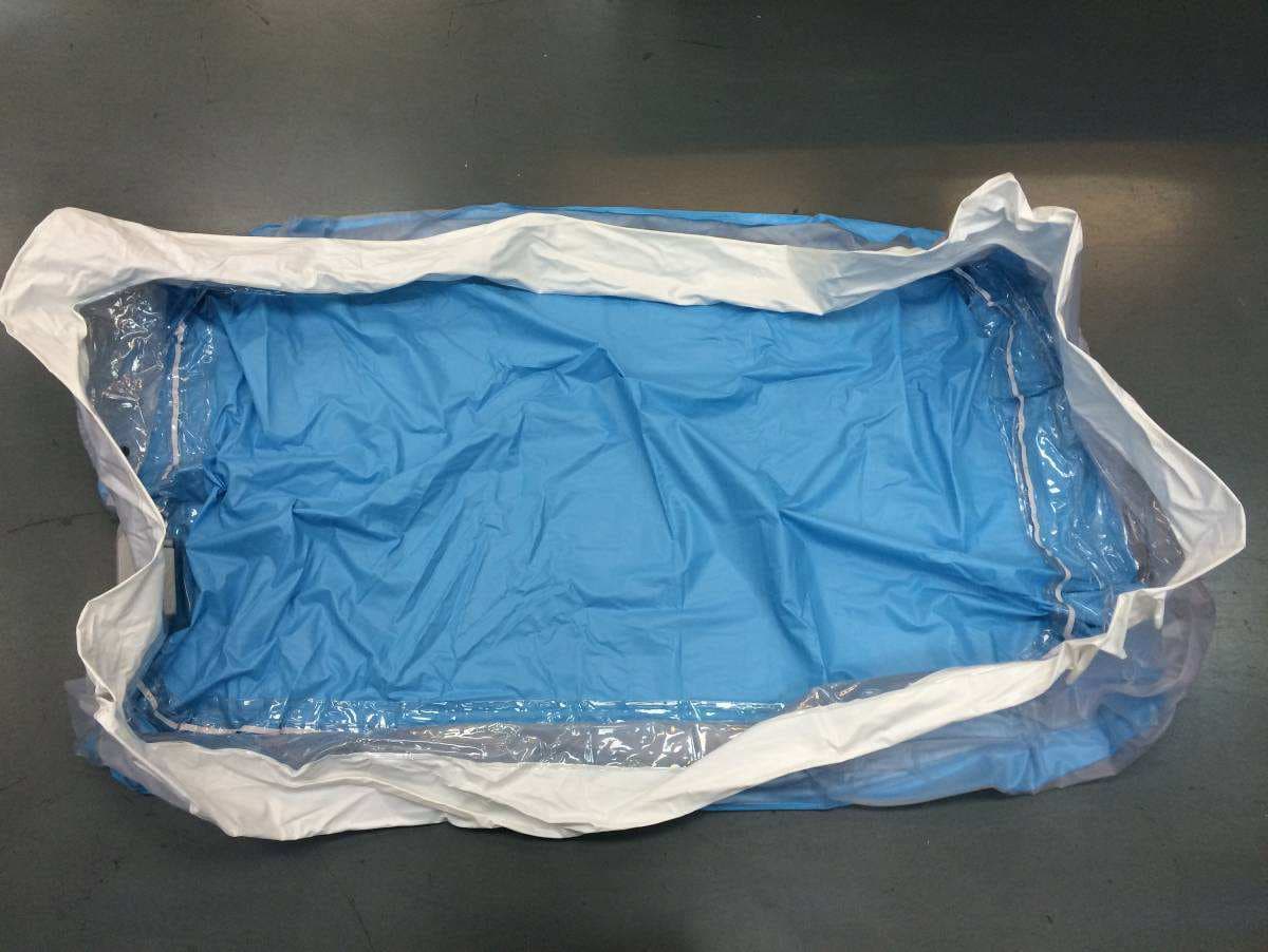
2AABT-LUMALIGHT
Nov 22, 2015Luma Light Pool
Equipment Class
CYY - Communications Receiver used w/Pt 15 Transmitter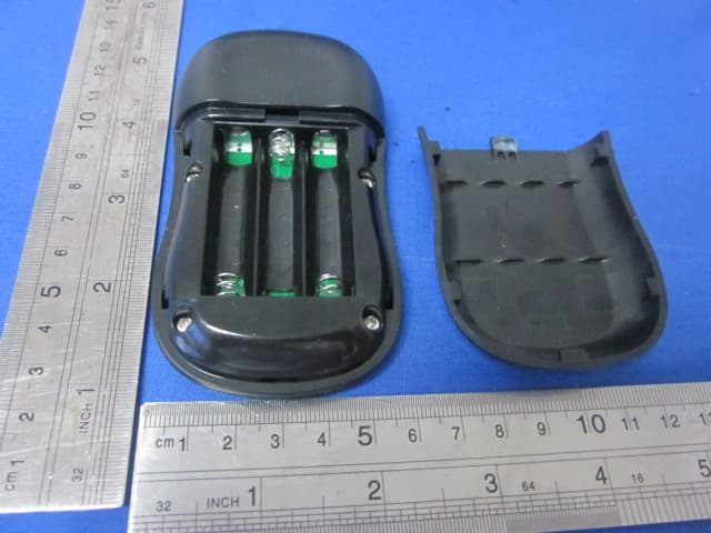
2AABTDLR-001
Apr 09, 2015Remote Controller
Equipment Class
DSC - Part 15 Security/Remote Control Transmitter
2AABTRGB105
Apr 01, 2015Digital light
Equipment Class
CYY - Communications Receiver used w/Pt 15 Transmitter
2AABT-CW003
May 20, 2014Christmas Tree Lighting
Equipment Class
CYY - Communications Receiver used w/Pt 15 Transmitter