2AABT-CW003Christmas Tree Lighting
Polygroup Limited(Macao Commercial Offshore)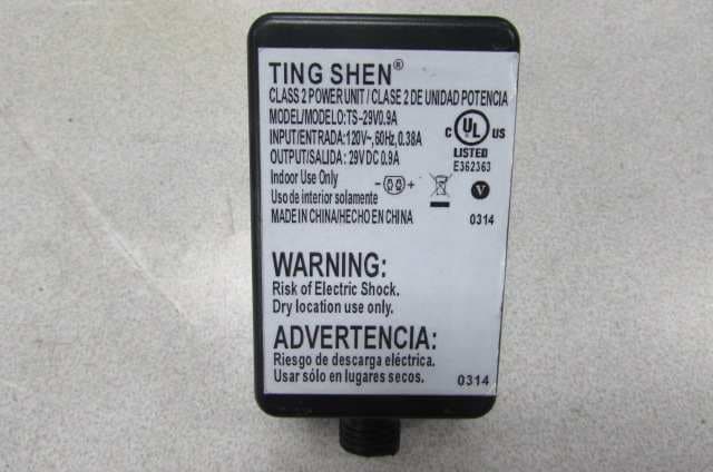
Click to zoom
Application Details
- Equipment Class
- CYY - Communications Receiver used w/Pt 15 Transmitter
- Date of Grant
- May 20, 2014
- Application Purpose
- Original Equipment
- Date of Application
- May 20, 2014
- Equipment Note
- Christmas Tree Lighting
- Frequency Range
- 433.92000000 - 433.92000000
- Country
- China
Documents & Files
Document Text
Text extracted from the exhibit documents filed with the FCC. Open a document above to read the original.
Users Manual
Section 3 Section 2 Section 1 90S 80S 100S 100S 80S 50S 50S Do Not Tamper Internal Parts Open the protective cover Do Not Tamper Internal Parts Open the protective cover Control box Safety Information Safety Information IMPORTANT SAFETY INSTRUCTIONS a.READ AND FOLLOW ALL SAFETY INSTRUCTIONS. When using electrical products, basic precautions should always be followed, including the following: b.Do not use seasonal products outdoors unless marked suitable for indoor and outdoor use. When products are used in outdoor applications, connect the product to a Ground Fault Circuit Interrupting (GFCI) outlet. If one is not provided, contact a qualified electrician for proper installa - tion. c. This seasonal product is not intended for permanent installation or use. d.Do not mount or place the product near gas or electric heaters, fireplaces, candles, or other similar sources of heat. e.Do not secure the wiring of the product with staples or nails, or place on sharp hooks or nails. f. Do not let lamps rest on the supply cord or on any wire. g.Unplug the product when leaving the house, when retiring for the night, or if left unattended. h.This is an electric product and not a toy! To avoid risk of fire, burns, personal injury and electric shock it should not be played with or placed where small children can reach it. i. Do not use this product for other than its intended use. j. Do not hang ornaments or other objects from cord, wire, or light string. k.Do not close doors or windows on the product or exten - sions cords as this may damage the wire insulation. l. Do not cover the product with cloth, paper, or any material that is not a part of the product when in use. m.This product has a polarized plug (one blade is wider than the other) as a feature to reduce the risk of electric shock. This plug will fit in a polarized outlet only one way. If the plug does not fit fully in the outlet, reverse the plug. If it still does not fit, contact a qualified electrician. Do not use with an extension cord unless plug can be fully inserted. Do not alter or replace the plug. n.This product is equipped with push-in type lamps. Do not twist lamps. o.This product employs overload protection (fuse). A blown fuse indicates an overload or short-circuit situation. If the fuse blows, unplug the product from the outlet. Also unplug any additional strings or products that may be attached to the product. Replace the fuse as per the user servicing instructions (follow product marking for proper fuse rating) and check the product. p.Read and follow all instructions that are on the product or provide with the product. q. SAVE THESE INSTRUCTIONS Step 1. Choose a location near a wall outlet. Step 2. Unfold the legs of the tree stand (D) and lay the stand on the floor. Step 3. Slide the locking disk of the tree stand (D) down until it snaps into place. Assembling the tree This tree assmebles with Quick Set® technology ---Set up and light up your tree in less than 10 minutes! Step 1.Remove the protective caps from the tree bottom (C) and insert the pole into the tree stand (D). Step 2.Remove the protective caps from the tree center (B) and insert the pole into the tree bottom (C) . Step 3.Insert the tree top (A) into the tree center (B). Step 4.Shape the branches to your preference by working from the bottom to the top. When adjusting branches, ensure that all wires are free of branch hinges. Step 5.Insert the green label extension cord plug into the wall outlet. All your lights should now be lit. Step 6.When finished shaping the branches, slightly upsweep all branch tips for a uniform look. Package Contents Assembly Assembling the tree stand Part Description Quantity A Tree top, tag 3 1 B Tree center, tag 2 1 C Tree bottom, tag 1 1 D Tree stand 1 Christmas Tree Model: DOU186755LEDCMR Sku # 1000 654 240 Adaptor To Be Plugged Into Wall Outlet NOTE: If some bulbs do not light or flicker, search for any loose plugs and/or broken, loose, or missing bulbs. Replace bulbs promptly with the replacement bulbs provided in order to maintain the performance and life expectancy of your tree. Step 1. Connect the light strings of the tree together and plug the power cord into a wall outlet. Step 2. If the tree comes with a foot pedal, step on the On/Off button. Press the selector button on the “Dual Color Light Control ler” or “Remote Controller” to select among: (1) CLEAR AND MULTI-COLOR ALTERNATING; (2) CLEAR LIGHTS; (3) MULTI LIGHTS and (4) TURN OFF BOTH LIGHTS. Note: The lights will be automatically reset to “CLEAR AND MULTI-COLOR ALTERNATING” every time the product is powered up. For the remote controller, replace only with CR2032 battery. See bottom of the remote controller for replacement instruction. a)Grasp plug and remove from the receptacle or other outlet device. Do not unplug by pulling on cord. b)Open fuse cover. Slide open fuse access cover on top of attachment plug towards blades. c)Remove fuse carefully. d)Risk of fire. Replace fuse only with 5,7, or10 Amp, 125 Volt fuse for the power cord set. e)Close fuse cover. Slide closed the fuse access cover on top of attachment plug. f )Risk of fire.Do not replace attachment plug. Contains a safety device (fuse) that should not be removed. Discard product if the attachment plug is damaged. CAUTION: Use only power adaptor that was provided with this product. Using a different power adaptor will damage the lights and cause fire, electrical shock hazard. Operation Turning on the tree HOW TO USE THE DUAL COLOR LIGHT CONTROLLER AND REMOTE CONTROL: Fuse replacement of extension cord This tree package includes hinge pins, washers, bulbs and fuse for any replacement or repair that you need to perform on your tree. If extra parts are needed, contact the Customer Service Team at 1-877-527-0313 between the hours of 8 am and 5 pm EST, Monday through Friday. Repairing Loose Hinges Step 1. Place the branch into the slot of the bracket Step 2. Insert a new hinge pin through the holes of the bracket …
Text truncated - open the document above for the full version.
Block Diagram
1234 A B C D 4321 D C B A Title NumberRevisionSize A4 Date:23-May-2013Sheetof File:E:\••\2013LS\RFFLASH\RFFlash(••2013-04-1000-12-33).ddbDrawnBy: BlockDiagram_RX MCU KEY RFRECEIVER RF Filter E? ANTENNA oscillator=8MHZ oscillator=6.7458MHZ*64 433.92MHZ D? LED D? LED DIRVE AdapterDC 29V DC 29V DC5V PDF• • •• "pdfFactory Pro" • • • • ••www.fineprint.com.cn
External Photos
Adapter for XY-2900800-U Adapter for TS-29V0.9A
ID Label/Location Info
LabelLabel locationLabel size Model:LxGxYxS FCC ID:2AABT-CW003 CAN RSS-Gen/CNR-Gen 20MM*10MM Label
Internal Photos
Adapter for XY-2900800-U Adapter for TS-29V0.9A
Operational Description
Part 1 This is a superheterodyne receiving circuit, the 433.92MHz carrier signal received by the antenna through L1, C1, L2, C2 filter circuit, the signal will input to 2 nd pin of IC SYN480. The signal is amplified by the IC, then mixing with the oscillator signatl to produce an intermediate frequency signal, which is filtered, amplified, demodulated the output signal of pin 6 to the MCU. (Oscillator signal from external crystal will produce input signal to the IC, then IC will magnify frequency internally 6.7458x64 = 431.7312MHz, Intermediate Frequency signal : 433.92-431 .7312 = 2.1888MHz). Part 2 This is the main part of the core circuit, the MCU’s operating frequency generated by the internal RC oscillator. RC oscillator is supplying a 4 MHz clock signal to the MCU. When a button is pressed or the received signal from the 7 th pin(MCU) and the 5 th pin(MCU), the MCU will produce the driving signal to the driving circuit that makes the lighting chains work. Part 3 This is a memory chip that can remember the current working state, the MCU can write and read out the corresponding function state. Part 4 After the adapter inputs a DC 29V voltage reduced to 5V by LM7805 , it will provide the electricity to MCU, memory chips, the driving circuit and the receiving circuit. Part 5 5 th pin(MCU) and 7 th pin (MCU) produce a signal to Q3, Q4, Q5 and driving H bridge circuit (composed by 4 MOSFET) to operate the lighting chain .
Test Report
Report No.: 140404080GZU-001 Issued: 07 May 2014 FCC ID: 2AABT-CW003 Page 2 of 19 CONTENT TEST REPORT ....................................................................................................................................................................... 1 CONTENT ............................................................................................................................................................................... 2 1 TEST RESULTS SUMMARY ...................................................................................................................................... 3 2 TEST RESULTS CONCLUSION ................................................................................................................................ 4 3 LABORATORY MEASUREMENTS .......................................................................................................................... 7 4 TEST RESULTS ............................................................................................................................................................ 8 4.1 CONDUCTED DISTURBANCE VOLTAGE AT MAINS PORTS.............................................................................................. 8 4.1.1 Used Test Equipment ......................................................................................................................................... 8 4.1.2 Block Diagram of Test Setup ............................................................................................................................. 8 4.1.3 Test Setup and Procedure .................................................................................................................................. 8 4.1.4 Limit................................................................................................................................................................... 9 4.1.5 Test Data............................................................................................................................................................ 9 4.1.6 Emission Curve ................................................................................................................................................ 12 4.1.7 Measurement Uncertainty................................................................................................................................ 13 4.2 RADIATED EMISSION (30 MHZ -1000 MHZ) .............................................................................................................. 14 4.2.1 Used Test Equipment ....................................................................................................................................... 14 4.2.2 Block Diagram of Test Setup ........................................................................................................................... 14 4.2.3 Field Strength Calculation............................................................................................................................... 15 4.2.4 Test Setup and Procedure ................................................................................................................................ 16 4.2.5 Limit................................................................................................................................................................. 16 4.2.6 Test Data.......................................................................................................................................................... 17 4.2.7 Test Curve........................................................................................................................................................ 18 4.2.8 Measurement uncertainty ................................................................................................................................ 19 Report No.: 140404080GZU-001 Issued: 07 May 2014 FCC ID: 2AABT-CW003 Page 3 of 19 1 TEST RESULTS SUMMARY Classification of EUT: Class B Test Item Standard Result Conducted disturbance voltage at mains ports FCC Part 15: 2013, Subpart B Pass Radiated emission (30 MHz–1 GHz) FCC Part 15: 2013, Subpart B Pass Radiated emission (Above 1 GHz) FCC Part 15: 2013, Subpart B Pass Remark: Reference publication is used for methods of measurement: ANSI C63.4:2009 Remark: 1. When determining the test results, measurement uncertainty of tests has been considered. Report No.: 140404080GZU-001 Issued: 07 May 2014 FCC ID: 2AABT-CW003 Page 4 of 19 2 Test Results Conclusion (with Justification) RE: EMC Testing Pursuant to FCC Part 15, Subpart B Performed On the Christmas Tree Lighting, Model: LxGxYxS(the first x=30-120, means the height of the tree; the second x=0-5 ,means the number of the cord set; the third x=0100-2300, means the number of LED). We tested the Christmas Tree Lighting, Model: L12G5R2000S, L12G5R2300S, to determine if they were in compliance with the relevant FCC rules as marked on the Test Results Summary. We found that the units met the requirement of FCC Part 15, Subpart B when tested as received. The worst case’s test data was presented in this test report. The Equipment Under Test (EUT) is controlled by a controller, the controller is an intentional radiator using 433.92MHz frequency. Antenna Type: PCB antenna. The controller option of this receiver is subject to Certification procedure. Model:LxGxYxS (Thirdly X=0100-0300) use the Adapter model XY-2900100UO Model:LxGxYxS (Thirdly X=0100-0600) use the Adapter model XY-2900200UO Model:LxGxYxS (Thirdly X=0100-0900) use the Adapter model XY-2900300U Model:LxGxYxS (Thirdly X=0100-0900) use the Adapter model XY-2900300UO Model:LxGxYxS (Thirdly X=0100-1100) use the Adapter model XY-2900400U Model:LxGxYxS (Thirdly X=0100-1100) use the Adapter model XY-2900400UO Model:LxGxYxS (Thirdly X=0100-1400) use the Adapter model XY-2900500-U Model:LxGxYxS (Thirdly X=0100-1400) use the Adapter model XY-2900500-UO Model:LxG…
Text truncated - open the document above for the full version.
Contact Information
Applicant
Nathan Ke
Technical Contact
Intertek Testing Services Shenzhen Ltd. GuangzhouJohn Meng
[email protected]86-20-82139718
Block E, No.7-2 Guang Dong Software Park, · Guangzhou, Guangdong Province · China
Test Firm
Intertek Testing Services Shenzhen Ltd.strong yao
[email protected]8628219940
Technical Specifications
| # | Rule Parts | Frequency Range | Power Output |
|---|---|---|---|
| 1 | 15B | 433.92 MHz - 433.92 MHz | - |
Other Applications from Polygroup Limited(Macao Commercial Offshore)
2AABT-LUMALIGHT-C
Nov 22, 2015Luma Light Pool
Equipment Class
DSC - Part 15 Security/Remote Control Transmitter
2AABT-LUMALIGHT
Nov 22, 2015Luma Light Pool
Equipment Class
CYY - Communications Receiver used w/Pt 15 Transmitter
2AABTDLR-001
Apr 09, 2015Remote Controller
Equipment Class
DSC - Part 15 Security/Remote Control Transmitter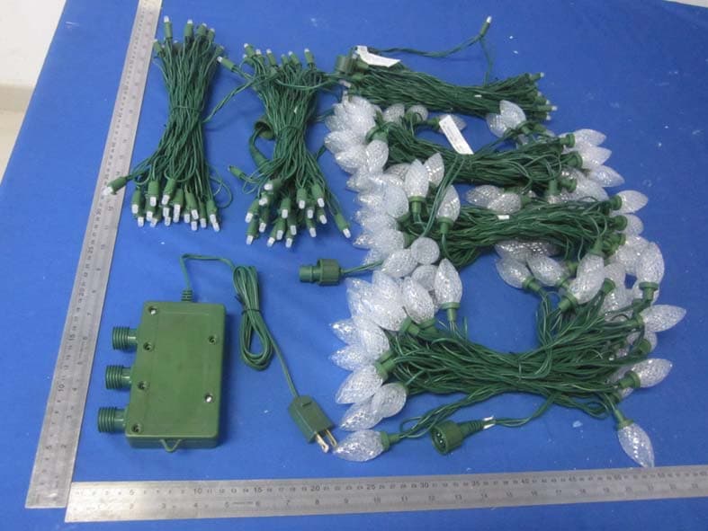
2AABTRGB105
Apr 01, 2015Digital light
Equipment Class
CYY - Communications Receiver used w/Pt 15 Transmitter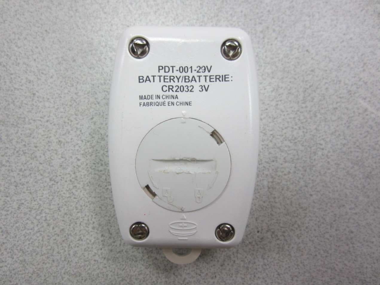
2AABT-CW001
Jun 20, 2013Low voltage quick set tree with remote controller
Equipment Class
DSC - Part 15 Security/Remote Control Transmitter